Skip to content

A customer once sent me a very clean aluminum enclosure drawing. The enclosure looked simple. Matte black powder coating. Logo printing. Several connector holes. A few mounting points inside. Nothing strange.
Then I noticed one small note on the drawing:
“Full powder coating required.”
At first glance, this sounds normal. Many customers want powder coating because it looks professional. It protects the enclosure. It gives the product a better brand feeling. For a custom enclosure, especially an OEM enclosure with a logo, this is often a good choice.
But I asked the customer one more question:
“Does this enclosure need grounding or EMI shielding?”
The customer paused.
That pause is very common.
Many buyers and product engineers think powder coating is only a surface finish. They think it only affects color, texture, and corrosion resistance. But in real enclosure projects, powder coating can also affect electrical grounding, chassis bonding, EMI shielding, and sometimes final product safety.
This is why I do not treat powder coating as only a cosmetic decision. I treat it as an engineering decision.
Why this question matters in custom electronic enclosures
For custom electronic enclosures, the metal housing is not only a shell. It can also work as part of the product’s electrical system.
It may help with:
- Protective grounding
- PCB chassis grounding
- EMI shielding
- ESD control
- Heat dissipation
- Mechanical protection
- Outdoor corrosion resistance
- Branding and appearance
The problem is simple. Powder coating is usually not conductive. It forms a layer between metal surfaces. That layer can stop direct electrical contact.
So a coated enclosure may look perfect from the outside, but inside, the grounding path may already be broken.
This is where many projects get into trouble.
A product engineer may design the enclosure as if the aluminum body is fully conductive. The purchasing team may order full powder coating for a better appearance. The factory may coat all surfaces because the drawing says “full coating.” Then, during assembly or EMC testing, the customer finds a grounding or shielding problem.
At that time, the enclosure is already produced.
And rework becomes painful.
The short answer: powder coating can affect grounding and EMI shielding
Yes, powder coating can affect electrical grounding and EMI shielding.
It affects them because it can block metal-to-metal contact.
Here is the simple logic:
| Item | Without Coating | With Standard Powder Coating |
|---|---|---|
| Metal surface conductivity | Good | Blocked by coating |
| Grounding contact | Easier | Needs exposed metal area |
| EMI shielding path | More continuous | May be interrupted at seams |
| Corrosion protection | Lower | Better |
| Appearance | Raw or simple | Better and more brand-friendly |
| Design risk | Lower for grounding | Higher if not controlled |
This does not mean powder coating is bad.
It means powder coating must be controlled.
I often tell customers: powder coating itself is not the enemy. The real problem is coating the wrong place without knowing it.
Why appearance, corrosion protection, and electrical performance must be balanced
In many real projects, the customer wants three things at the same time:
- The enclosure should look good.
- The enclosure should resist corrosion.
- The enclosure should support grounding or EMI shielding.
These three goals can fight each other.
A thick powder coating looks good and protects the enclosure. But it can also block electrical contact. Bare metal gives better electrical contact. But bare metal may oxidize, scratch, or corrode. Conductive coating may sound like a perfect solution. But it may increase cost and still needs testing.
So the right answer is not always “coat everything” or “do not coat anything.”
The right answer is usually:
Coat the cosmetic and protection areas. Keep the electrical contact areas controlled and exposed.
Before I approve a powder coating plan, I always want to know whether the enclosure is just a protective box or part of the electrical design. This small question can save a project from a very expensive mistake later.
And this brings us to the first real issue: what actually happens when powder coating covers a metal enclosure?
What Happens When Powder Coating Covers a Metal Enclosure?
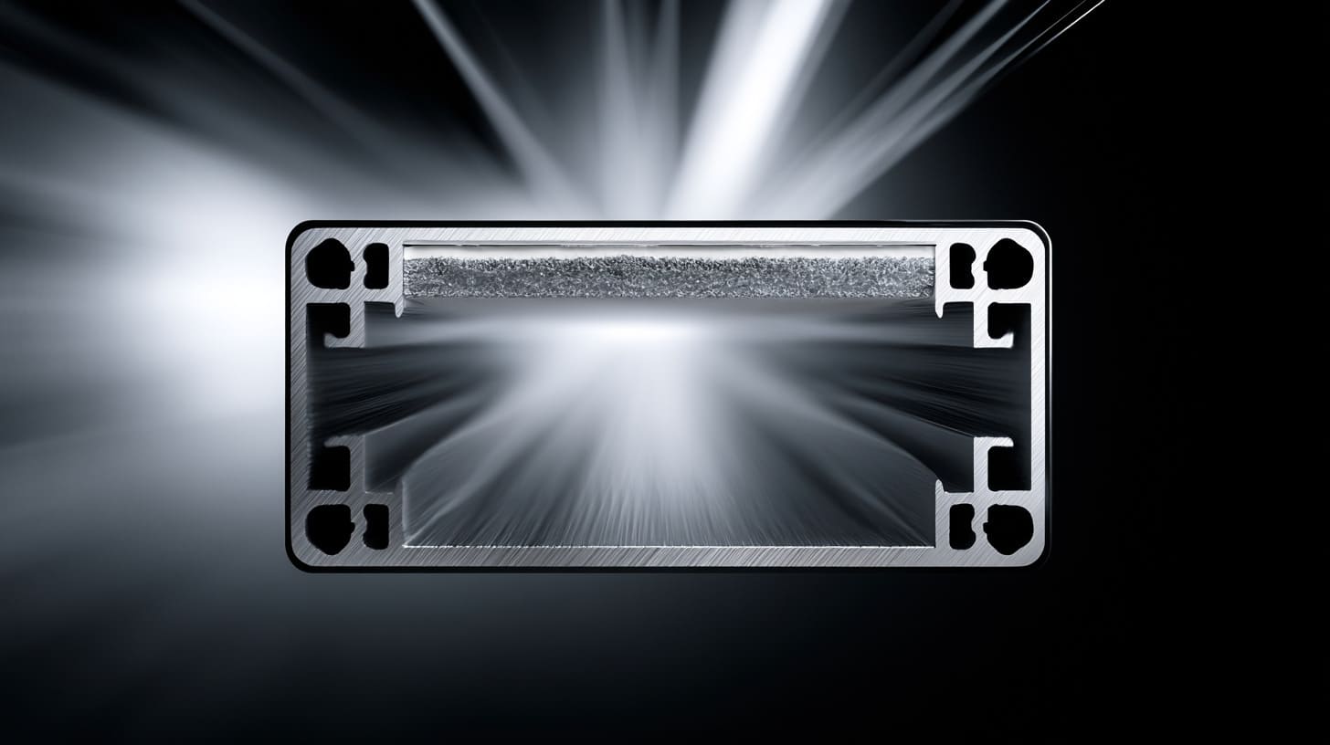
Powder coating looks simple after it is finished. You see a smooth surface. Maybe it is matte black. Maybe it is white, gray, or textured. The product looks clean and strong.
But under that surface, something important has changed.
The metal is no longer directly exposed.
Powder coating creates an insulating layer on conductive metal
Aluminum and steel are conductive materials. When they are bare, current can pass through their surface. This is useful when the enclosure needs grounding or EMI shielding.
Powder coating adds a polymer layer on top of the metal. This layer is usually an electrical insulator.
That means the surface may no longer conduct electricity where the powder coating covers it.
This matters a lot in areas like:
- Cover-to-body contact
- Screw mounting areas
- Grounding studs
- PCB mounting points
- Connector cutouts
- EMI gasket contact surfaces
- Door and panel seams
A powder-coated surface may still look like metal from a distance. But electrically, it may act like plastic.
This is the part many people underestimate.
Coating thickness can block metal-to-metal contact
Powder coating has thickness. It is not just color.
The thickness depends on the coating type, process, surface shape, and factory control. In many enclosure projects, the coating may be thick enough to change assembly fit and block contact.
For normal appearance and protection, this is fine. For electrical contact, it can become a problem.
| Area | Why coating thickness matters |
|---|---|
| Screw holes | Coating may reduce hole size and block contact |
| Threaded holes | Threads may become tight or insulated |
| Cover edges | Coating may stop cover and body from touching |
| Mounting pads | PCB ground may not connect to chassis |
| Connector openings | Shielded connectors may not bond to enclosure |
| Gasket areas | EMI gasket may press against paint, not metal |
This is why I never only ask, “What color do you need?”
I also ask, “Which areas must still conduct after coating?”
A beautiful finish can hide a broken electrical path. That is why I do not judge powder coating only by surface appearance. I judge it by what the enclosure needs to do after assembly.
Most customers check the outside first. That is normal. The outer surface is what end users see. It affects branding. It affects the feeling of quality.
But the electrical risks are usually hidden inside.
For example, a screw hole may be coated. A grounding stud may have coating around the base. A cover seam may have no bare metal contact. A shielded RJ45 connector may sit on a coated panel and fail to bond with the enclosure.
These are small details. But they can decide whether the product passes testing.
One customer once asked why I cared so much about a tiny uncoated ring around a screw hole. From his side, it looked ugly. From my side, that tiny ring was the grounding path.
This is the kind of detail that separates a normal enclosure from an engineered enclosure.
And once we understand this layer problem, the next question becomes more direct: how exactly does it affect grounding?
Does Powder Coating Affect Electrical Grounding?
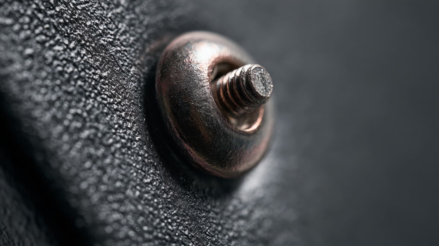
Yes, powder coating can affect electrical grounding.
Grounding needs a reliable conductive path. If powder coating sits between two metal parts, that path may become weak or completely blocked.
This is not only a theory. It happens in real assembly.
Why grounding depends on low-resistance contact points
Grounding is not magic. It needs contact.
A good grounding path usually needs:
- Clean metal surface
- Enough contact area
- Enough contact pressure
- Stable screws or fasteners
- Low resistance between parts
- No paint, oil, dirt, or oxide blocking the path
If the enclosure body is bare metal, a screw, stud, or bracket may create contact easily. If the surface is powder coated, the same screw may only touch the coating.
That means the screw may be mechanically tight but electrically poor.
This is dangerous because the assembly may look correct.
The screw is there. The nut is tight. The drawing looks followed. But the electrical path may not be reliable.
How coated screw holes, studs, and mounting pads cause grounding failure
In custom enclosures, grounding often depends on small areas.
For example:
| Grounding Area | Common Problem After Powder Coating | Possible Result |
|---|---|---|
| Grounding stud | Coating covers the base area | Poor chassis ground |
| Screw hole | Coating covers the hole wall | Screw does not contact metal |
| PCB mounting pad | Coating covers the standoff area | PCB ground does not bond to enclosure |
| Cover screw area | Coating covers both mating surfaces | Cover is not bonded to body |
| Cable gland area | Coating blocks metal gland contact | Shield or earth path becomes weak |
A very common mistake is thinking the screw will cut through the coating automatically.
Sometimes it does. Sometimes it does not.
It depends on coating thickness, screw type, torque, material hardness, washer design, and vibration. If the product is used in the field for years, the contact can also change.
For a low-risk plastic device, this may not matter. For industrial control, power supply, outdoor telecom, battery system, or high-frequency device, it matters a lot.
When grounding still works after powder coating
Grounding can still work with powder coating if the design controls the contact areas.
For example, the manufacturer can:
- Mask grounding points before coating
- Keep studs and pads bare
- Use serrated washers
- Use grounding clips
- Remove coating after coating in selected areas
- Add dedicated grounding wires
- Use conductive gaskets or bonding straps
- Test continuity after finishing
A powder-coated enclosure can still have good grounding. But it does not happen by luck. It happens by design and inspection.
Here is a simple way I think about it:
| Situation | Risk Level |
|---|---|
| Full coating with no grounding note | High |
| Coating with masked grounding points | Lower |
| Coating with continuity test | Much safer |
| Coating plus dedicated ground wire | Better for critical projects |
| Coating plus EMI gasket design | Better for EMI-sensitive products |
I become careful when a drawing only says “powder coating black” and says nothing about grounding. In that situation, I know the finish instruction is clear, but the electrical intention is still missing.
Never assume a coated part is still electrically continuous
A coated enclosure may still be metal. But that does not mean every part of it is electrically connected.
This is especially true when the enclosure has:
- Separate covers
- Removable panels
- Hinged doors
- Internal brackets
- Coated fasteners
- Coated contact zones
If the product needs safety grounding, I prefer to see a clear grounding point on the drawing. If the PCB needs chassis grounding, I want that contact area defined. If EMI shielding matters, I want the cover, body, gasket, and connector contact zones checked together.
Grounding is not only about one screw.
It is about the full path.
A small blocked contact point can break the whole chain.
Once grounding is affected, EMI shielding becomes the next concern. Because EMI shielding also depends on metal continuity, and powder coating can quietly break that continuity at the worst places.
Does Powder Coating Affect EMI Shielding Performance?
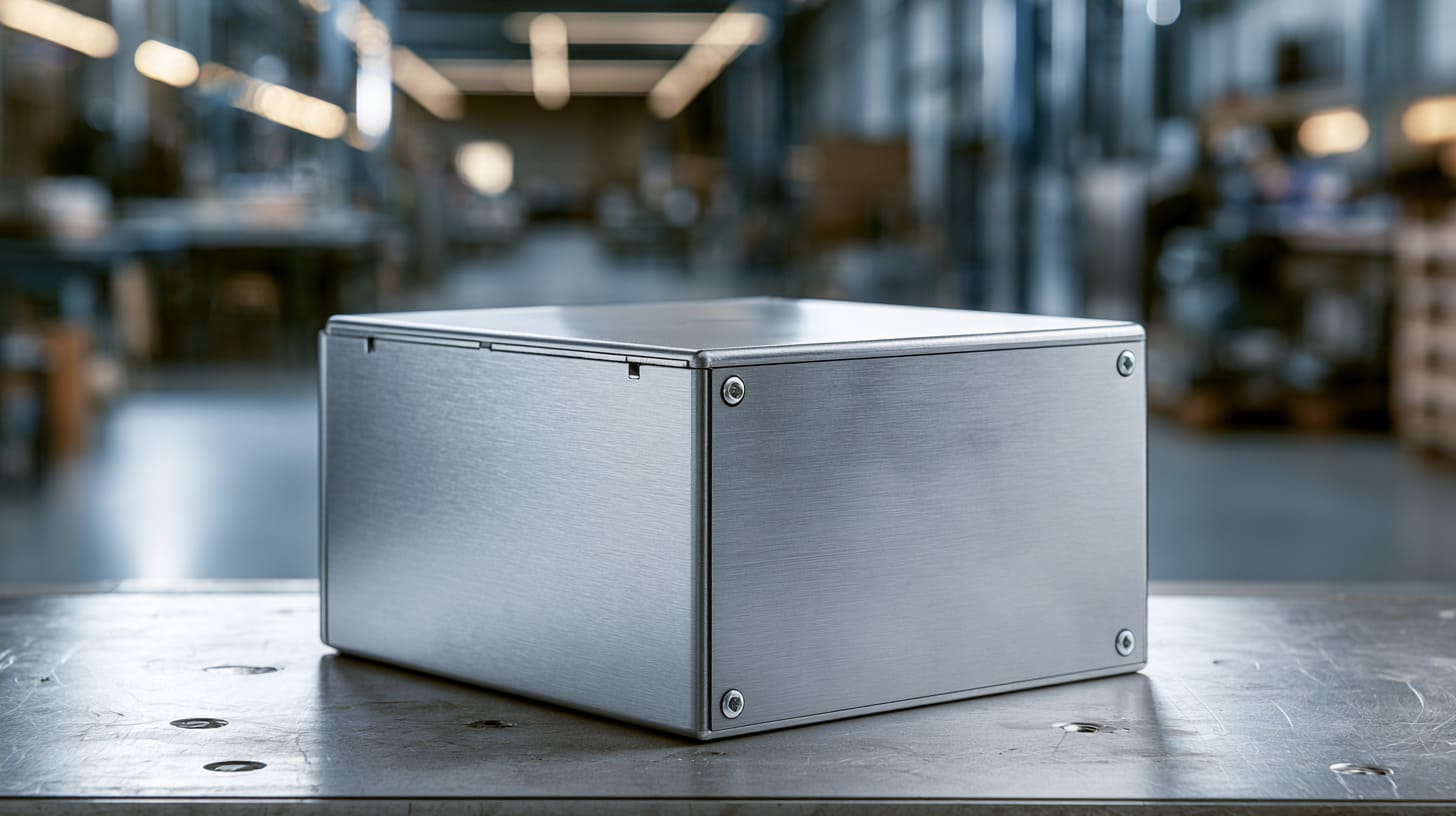
Powder coating can affect EMI shielding performance, especially at seams and contact points.
The metal enclosure itself can help block electromagnetic interference. But only when the conductive path is continuous enough for the application.
A metal box with painted contact surfaces may not perform like a fully bonded metal box.
EMI shielding needs a continuous conductive enclosure path
EMI shielding works better when the enclosure forms a conductive barrier around the electronics.
In simple words, the enclosure should act like a shield.
But a shield needs continuity.
If the enclosure body, cover, connector plate, and door are not electrically connected, the shielding performance can drop. EMI can leak through gaps, seams, holes, and poorly bonded interfaces.
Common weak areas include:
- Cover seams
- Door frames
- Connector panels
- Vent openings
- Cable entry points
- Unbonded brackets
- Coated screw areas
- Plastic inserts
- Display windows
A fully sealed-looking enclosure is not always an EMI-tight enclosure.
Waterproof and EMI shielding are also not the same thing.
A rubber gasket may block water, but it may not conduct electricity. An EMI gasket may conduct, but it must press against bare or conductive surfaces. This is where many designs get confused.
How seams, doors, covers, and panels become weak points
EMI often escapes from openings and seams.
Even a small gap can matter, especially at higher frequencies. A powder-coated seam can make the problem worse because the cover may touch the body mechanically but not electrically.
Let me make it practical.
| Enclosure Area | Mechanical View | EMI View |
|---|---|---|
| Cover seam | Cover is closed and screws are tight | Is there conductive contact around the seam? |
| Door frame | Door closes well | Is the gasket conductive and compressed correctly? |
| Connector hole | Connector fits the cutout | Does the connector shield bond to bare metal? |
| Screw area | Screw holds parts together | Does the screw create reliable electrical bonding? |
| Panel joint | Panel aligns with body | Is the joint electrically continuous? |
This is why EMI problems often surprise people.
The enclosure may pass visual inspection. It may pass assembly inspection. It may even pass basic fit testing. But when the customer does EMC testing, the small gaps start to speak.
And they speak loudly.
Why a grounded metal shell can still perform if contact points are controlled
Powder coating does not automatically destroy EMI shielding.
If the contact points are well designed, the enclosure can still work well.
For example:
- Outer surfaces can be powder coated for appearance
- Internal grounding areas can remain bare
- Cover seams can use conductive gaskets
- Connector shield areas can be masked
- Grounding studs can be left uncoated
- Critical joints can be checked with continuity testing
The idea is not to remove all powder coating.
The idea is to keep the right electrical paths alive.
For many industrial products, this balance is very practical. The product still looks good. It still resists corrosion. It still has usable EMI performance.
But the drawing must make this clear.
If the drawing does not show the electrical contact areas, the factory may coat them by default. And from the factory side, that may look like following the drawing correctly.
EMI problems often start at small assembly interfaces
I do not worry first about the large flat outside surface. I worry more about the 5 mm contact strip near the cover, the small washer under a screw, or the connector flange touching a painted panel.
Those areas look small, but they carry the real EMI path.
This is also why I like to discuss EMI early. If a customer only mentions EMI after the coating is finished, the solution becomes harder. We may need to remove coating, add gaskets, add bonding wires, or redesign contact points.
That costs time.
And in B2B custom projects, time is often the real pressure.
The next practical question is clear: which areas should we keep free from powder coating?
Which Areas Should Not Be Powder Coated?
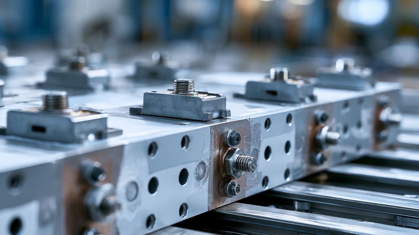
Not every surface should be coated.
For a normal decorative enclosure, full powder coating may be fine. But for an enclosure with grounding or EMI requirements, some areas should stay bare or be specially controlled.
This should be decided before production.
Not after coating.
Grounding studs and bonding points
Grounding studs are one of the most important areas.
If the base of the grounding stud is coated, the grounding wire may not bond well to the enclosure body. The nut may be tight, but the electrical connection may still be poor.
For grounding studs, I usually suggest:
- Keep the stud contact area bare
- Mask the stud before coating
- Use proper washers
- Mark the grounding point clearly
- Test continuity after coating
- Avoid coating buildup near the grounding area
A grounding point should not be treated like a cosmetic area.
It has a job.
That job is safety and electrical reliability.
Gasket contact surfaces
For EMI shielding, gasket contact surfaces are critical.
A normal rubber gasket does not need bare metal for water sealing. But an EMI gasket usually needs conductive contact. If both sides are powder coated, the EMI gasket may press against insulation.
That means the gasket is there, but the shielding path is weak.
| Gasket Type | Main Purpose | Surface Requirement |
|---|---|---|
| Rubber gasket | Waterproof sealing | Smooth compression surface |
| Foam gasket | Dust or light sealing | Even surface |
| Conductive EMI gasket | EMI shielding | Conductive contact surface |
| Combination gasket | Sealing + EMI | Controlled surface and pressure |
This is why I ask what kind of gasket the customer will use.
If it is only for waterproofing, coating may be acceptable. If it is for EMI, the contact surface needs more attention.
Screw bosses, mounting pads, and threaded holes
Screw bosses and mounting pads are small, but they often decide grounding quality.
If a PCB ground connects to a standoff, and the standoff sits on a coated surface, the chassis connection may fail.
Threaded holes can also become a problem. Powder coating can enter threads and make assembly difficult. It can also insulate screws from the metal.
For important threaded holes, the drawing should define whether they need:
- Masking before coating
- Tapping after coating
- Cleaning after coating
- Bare metal contact around the hole
- Conductive washer contact
Without this note, the result depends too much on habit.
And habit is not a reliable engineering method.
Connector cutouts and shield termination areas
Shielded connectors need careful contact.
RJ45 connectors, USB ports, D-sub connectors, SMA connectors, and other shielded interfaces may need to bond to the enclosure. If the connector flange touches only powder coating, the shield may not connect properly.
This is common in communication devices, industrial controllers, IoT gateways, and RF equipment.
For connector areas, I usually check:
| Connector Area | What to Check |
|---|---|
| Flange surface | Does it touch bare metal? |
| Screw fixing area | Does the screw bond the connector shield? |
| Cutout edge | Is the coating too thick for fit? |
| Panel thickness | Does coating affect insertion? |
| Ground path | Does the connector shield connect to chassis? |
A connector hole is not only a hole.
Sometimes it is part of the electrical design.
Masking is cheaper than fixing EMI failure later
When I see a drawing with EMI or grounding requirements, I prefer to mask a few small areas first, even if it adds some process time. Fixing failed EMC testing later is far more expensive than protecting the right contact zones at the beginning.
Masking is not beautiful work. It is slow. It requires care. It may look like a small production detail.
But for the final product, it can be the difference between smooth assembly and late-stage failure.
Now the next question is how the manufacturer can actually protect these areas during powder coating.
How Can Manufacturers Protect Grounding During Powder Coating?

Good powder coating control starts before the part enters the coating line.
If the factory only thinks about color, the result may look good but fail electrically. If the factory thinks about function first, the coating process can be planned around grounding and EMI needs.
This is where communication between customer and supplier becomes very important.
Use masking plugs, tapes, and caps before coating
Masking is one of the most common ways to protect contact areas.
The factory can use:
- Silicone plugs
- High-temperature tapes
- Threaded caps
- Custom masking fixtures
- Rubber covers
- Special masking stickers
These protect selected areas from powder coating.
For example, threaded holes can be plugged. Grounding pads can be taped. Studs can be capped. Gasket contact strips can be masked.
The key is accuracy.
If the masked area is too small, contact may be poor. If the masked area is too large, the exposed metal may look ugly or reduce corrosion protection. So the drawing should define the required area clearly.
| Area to Mask | Common Masking Method | Main Purpose |
|---|---|---|
| Threaded hole | Silicone plug | Keep thread clean |
| Grounding pad | High-temp tape | Keep metal exposed |
| Stud | Cap or sleeve | Avoid coating on contact area |
| Gasket strip | Tape or fixture | Maintain conductive path |
| Connector area | Custom mask | Ensure shield contact |
Masking sounds simple. But in production, it needs discipline.
A worker may miss one hole. Tape may shift. Powder may enter from the side. The QC team must check it.
Add welded studs or PEM fasteners in the right sequence
The production sequence matters.
For sheet metal enclosures, we may need PEM nuts, PEM studs, welded studs, or riveted hardware. Some should be installed before coating. Some may be better after coating. It depends on the part function.
For grounding, I often prefer stable metal hardware with a clear contact path.
But the sequence must be controlled.
If we install a stud before coating, we must protect the contact area. If we install it after coating, we need to avoid damaging the finish and still keep electrical contact.
There is no single answer for every enclosure.
| Fastener Type | Possible Process | Risk |
|---|---|---|
| Welded stud | Before coating | Coating may cover base if not masked |
| PEM stud | Before coating | Coating may affect threads or contact |
| Rivet nut | Before or after coating | Contact may be unstable if surface is coated |
| Ground screw | During assembly | Needs bare metal or conductive washer |
| External ground lug | After coating | Needs controlled contact area |
This is where experienced process planning helps.
A good enclosure supplier should not only ask what finish you want. The supplier should also ask how the enclosure will be grounded and assembled.
Remove coating locally by machining or scraping when necessary
Sometimes coating is removed after finishing.
This can be done by:
- Spot facing
- Light machining
- Sanding
- Scraping
- Thread chasing
- Cleaning contact pads
This method can work. But it is not always my first choice.
Why?
Because post-removal can scratch visible surfaces. It can create inconsistent exposed areas. It can add labor cost. It can also leave bare metal without corrosion protection if the area is not controlled.
Still, it is useful when the drawing was not clear or when only a small area needs correction.
For stable mass production, I prefer planned masking instead of random scraping after coating.
Define bare metal zones clearly on the drawing
The drawing should show where coating is not allowed.
A simple note like “mask grounding point” may not be enough for a complex enclosure.
Better notes include:
- No coating on grounding pad
- Mask area diameter 8 mm around grounding stud
- No coating on EMI gasket contact surface
- Threads must be clean after coating
- Conductivity required between cover and body
- Continuity test required after finishing
This turns the requirement from a verbal discussion into a production instruction.
That matters because many people touch one order:
- Sales
- Engineer
- Production planner
- Sheet metal team
- Coating supplier
- QC inspector
- Assembly worker
- Packing team
If the requirement is only in an email, it may be missed. If it is on the drawing, the chance is much better.
When I see unclear grounding requirements, I would rather slow down and confirm them than push the order too fast. Fast production feels good for two days, but a wrong coating decision can delay the whole project for weeks.
After this, some customers ask me another question: can conductive powder coating solve everything?
What About Conductive Powder Coating?

Conductive powder coating sounds attractive.
It sounds like we can get surface protection and electrical conductivity at the same time. In some cases, it may help. But I do not treat it as a magic answer.
A conductive finish still needs proper design, contact pressure, testing, and process control.
What conductive powder coating is
Conductive powder coating is a coating designed to provide some level of electrical conductivity.
It may use conductive fillers or special materials to reduce surface resistance. It can be used for ESD control, EMI support, or special industrial applications.
But “conductive” is a broad word.
It does not always mean the coating can replace bare metal contact.
Different conductive coatings can have different:
- Surface resistance
- Thickness
- Adhesion
- Durability
- Cost
- Color options
- Finish quality
- Process stability
- Testing requirements
So I always ask for the real performance requirement, not only the word “conductive.”
When conductive coating may help EMI or ESD control
Conductive coating may help in some cases.
For example:
- Plastic enclosures needing EMI shielding
- Aluminum enclosures needing controlled surface conductivity
- ESD-sensitive products
- Internal shielding surfaces
- Special electronic equipment
- Products where bare metal is not acceptable
For plastic enclosures, conductive coating or plating may be one way to add shielding. For aluminum enclosures, conductive coating may help in selected areas, but it still may not replace direct bonding where strong grounding is needed.
Here is a simple comparison:
| Use Case | Conductive Coating May Help? | Still Need Design Control? |
|---|---|---|
| ESD control | Yes | Yes |
| EMI shielding on plastic housing | Yes | Yes |
| Grounding safety point | Maybe, but not preferred alone | Definitely |
| Connector shield bonding | Sometimes | Yes |
| Outdoor corrosion + EMI | Maybe | Yes, with testing |
| High-reliability industrial device | Case by case | Always |
Why conductive coating is not always equal to a proper grounding design
A proper grounding design needs a reliable path.
That path should stay stable after:
- Assembly
- Vibration
- Temperature change
- Humidity
- Aging
- Maintenance
- Screw removal and re-tightening
A coating may be conductive on paper, but the real contact may still depend on pressure and surface condition.
If the product has safety grounding, I prefer a dedicated and tested metal contact point. I do not like to rely only on a coating unless the customer has tested and approved that method.
Conductive coating can support the design.
But it should not replace thinking.
Cost, availability, consistency, and testing concerns
Conductive powder coating may cost more than standard powder coating. It may also have fewer color and texture options. Some suppliers may not have stable experience with it. Some finishes may need special testing.
For OEM buyers, this matters.
A beautiful idea in design may become difficult in production if the process is not common.
| Factor | Standard Powder Coating | Conductive Powder Coating |
|---|---|---|
| Cost | Lower | Higher |
| Color options | More | Usually fewer |
| Supplier availability | Common | More limited |
| Process control | Easier | More sensitive |
| Electrical performance | Usually insulating | Depends on type |
| Testing need | Normal coating checks | Electrical checks needed |
My concern with conductive coating is not only whether it works once. I care whether it can work the same way over many batches. For custom OEM orders, repeatability is often more important than one perfect sample.
So conductive coating may be useful. But it should be selected with clear expectations.
This leads to a more common comparison: powder coating, bare metal, and anodizing. Which one is better for EMI?
Powder Coating vs Bare Metal vs Anodizing for EMI
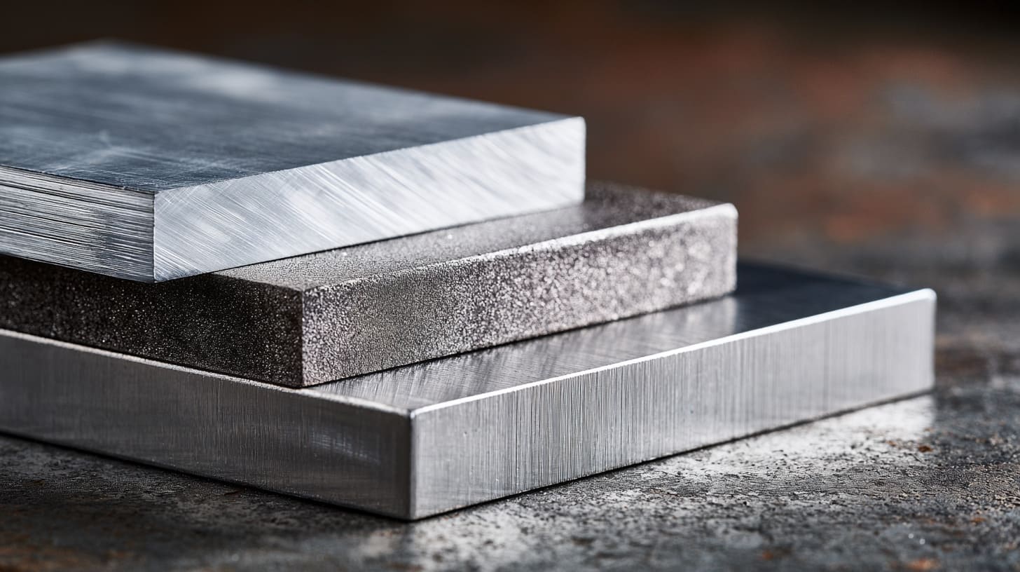
There is no single best surface finish for every EMI project.
Each finish has strengths and weaknesses. The right choice depends on the enclosure’s function, environment, appearance requirement, and testing target.
This is why I do not like simple answers like “powder coating is bad” or “anodizing is always better.”
Real projects are not that clean.
Bare metal: better conductivity, weaker surface protection
Bare metal gives good electrical contact. It is useful for grounding and EMI bonding.
But bare metal also has weaknesses.
It can:
- Scratch easily
- Oxidize over time
- Look unfinished
- Corrode in harsh environments
- Create cosmetic inconsistency
- Require special packaging and handling
For internal contact areas, bare metal is often useful. For full external surfaces, it may not be acceptable, especially for branded products.
A product sold on Amazon or used in a finished industrial system usually needs a better appearance.
So bare metal is good for function, but not always good for product feeling.
Powder coating: better appearance and corrosion resistance, weaker conductivity
Powder coating is very common because it solves many practical problems.
It gives:
- Good appearance
- Color control
- Texture options
- Corrosion resistance
- Brand consistency
- Better surface durability
- Good value for many enclosure projects
But for grounding and EMI, standard powder coating needs control.
If we coat all contact areas, electrical performance may drop.
So powder coating is not wrong. It just needs selective masking or a clear grounding design.
Anodizing: thinner than powder coating but still electrically resistive
Many customers think anodizing is conductive because it is thinner than powder coating.
This can be misleading.
Anodizing forms an oxide layer on aluminum. That layer is usually electrically resistive. It may be thinner than powder coating, but it can still affect electrical contact.
For extruded aluminum enclosures, anodizing is common. It looks clean and keeps the metal feeling. It can also be better for dimension control than thick powder coating.
But if grounding is required, we still need to check contact areas.
| Finish | Appearance | Corrosion Protection | Conductivity at Surface | EMI/Grounding Risk |
|---|---|---|---|---|
| Bare aluminum | Raw metal look | Lower | Better | Lower, but oxidation still matters |
| Powder coating | Strong color and texture | Good | Poor for standard coating | Higher if contact areas are coated |
| Anodizing | Clean metallic finish | Good | Often resistive | Medium, still needs contact control |
| Conductive coating | Special finish | Depends | Better than normal coating | Depends on testing and process |
The best finish depends on the real electrical function
I choose surface finish by asking what the enclosure must do, not by asking which finish sounds better. If the enclosure only needs appearance and corrosion protection, powder coating is easy. If it also needs EMI shielding, the finish must be designed around the contact path.
This is also why two products that look similar may need different finishing plans.
One aluminum box may only protect a low-power controller. Another similar box may house RF electronics. One can use full powder coating. The other may need masked gasket areas, exposed connector contact, and continuity testing.
Same shape.
Different risk.
And many design mistakes happen because people treat them as the same.
Common Design Mistakes Engineers Make

Many grounding and EMI issues do not come from bad suppliers.
They come from missing details at the drawing stage.
A drawing may look complete mechanically, but still be incomplete electrically. This is very common in custom enclosure work.
Specifying full powder coating without grounding notes
This is the mistake I see most often.
The drawing says:
- Powder coating: matte black
- Full surface coating
- Texture finish
- Logo printing
But it does not say:
- Which area must be bare
- Where the grounding point is
- Whether EMI shielding is required
- Whether the cover must bond to the body
- Whether connector shields need chassis contact
From the factory view, “full powder coating” means coat everything unless told otherwise.
So the factory may do exactly what the drawing says.
But the product may fail what the engineer expected.
That is a communication gap.
Forgetting coating thickness in assembly tolerance
Powder coating adds thickness.
This can affect:
- Holes
- Slots
- Covers
- Sliding parts
- Hinges
- Threads
- Gasket compression
- Connector fit
- Panel assembly
For grounding and EMI, coating thickness can also affect contact pressure.
If a gasket needs compression, thick coating may change the gap. If a connector needs a tight fit, coating may make the cutout too small. If a screw needs metal contact, coating may block it.
| Design Area | What Can Go Wrong |
|---|---|
| Tight cover fit | Coating makes assembly hard |
| Small holes | Coating reduces hole size |
| Threads | Screws become tight |
| Gasket groove | Compression changes |
| Connector cutout | Connector does not seat properly |
| Ground pad | Contact becomes insulated |
This is why tolerance and finishing should be discussed together.
They are not separate topics.
Assuming screws will automatically cut through coating
Some engineers believe screws will break through powder coating and create contact.
Sometimes this happens. But I do not like relying on it.
Why?
Because it is not controlled.
One screw may cut through. Another may not. One worker may use enough torque. Another may not. One batch may have thinner coating. Another batch may be thicker.
A grounding method should not depend on luck.
If the screw is part of the electrical path, then the design should support it with:
- Bare contact area
- Serrated washer
- Defined torque
- Conductivity test
- Proper fastener material
- Stable assembly process
A screw is good for mechanical fastening.
It is not automatically a good electrical design.
Painting both sides of mating metal surfaces
This is another quiet mistake.
If the cover and body both have powder coating at the contact seam, they may not bond electrically.
The same issue can happen with:
- Brackets
- Mounting plates
- Hinges
- Doors
- Rear panels
- Internal partitions
Mechanically, the parts are connected.
Electrically, they may be separated.
This matters for EMI because the shield needs continuity across parts.
If each panel becomes an isolated island, the enclosure will not behave like one complete metal shield.
Ignoring EMI gasket compression and contact pressure
An EMI gasket needs more than just placement.
It needs the right contact pressure.
If compression is too low, shielding may be weak. If compression is too high, the gasket may deform or assembly may become difficult. If the gasket presses against powder coating, conductivity may be poor.
So we must check:
- Gasket type
- Compression range
- Contact surface
- Screw spacing
- Flatness
- Coating thickness
- Long-term compression set
This is detailed work.
But EMI is detailed work.
The mistake I watch for is a drawing that looks mechanically finished but has no electrical contact logic. A nice 3D model can still fail if nobody asks how current or interference will move through the enclosure.
After seeing these mistakes many times, I prefer to make the specification clearer from the beginning.
How to Specify Powder Coating When Grounding or EMI Matters
A good specification makes production easier.
A vague specification makes everyone guess.
For powder-coated enclosures with grounding or EMI requirements, the drawing should not only define color and texture. It should define function.
Mark all “no coating” areas in the 2D drawing
The most direct method is to mark all no-coating areas.
These areas may include:
- Grounding pads
- Stud bases
- Screw contact areas
- EMI gasket surfaces
- Connector shield contact areas
- Cover bonding points
- Internal mounting pads
It is better to show size and position.
For example:
| Drawing Note | Better or Worse? | Reason |
|---|---|---|
| “Leave grounding area uncoated” | Better than nothing | But still not very precise |
| “No coating around grounding stud” | Better | Gives direction |
| “Mask Ø10 mm area around grounding stud” | Much better | Clear for production and QC |
| “No coating on gasket contact strip, width 6 mm” | Good | Clear contact surface |
| “Threads must be clean after coating” | Good | Prevents assembly issue |
The clearer the drawing, the less back-and-forth communication.
That matters when supplier and customer are in different time zones.
Add clear grounding and bonding requirements
Grounding and bonding requirements should be written clearly.
For example:
- Protective earth point required
- Chassis grounding point required
- Cover must be bonded to body
- Resistance between cover and body must be tested
- Grounding stud must remain conductive
- Connector shield must contact chassis
These notes help the supplier understand the reason behind the masking.
Without the reason, the factory may think the bare area is only a cosmetic detail. With the reason, the factory knows it is functional.
This changes how carefully people handle it.
Define masking tolerance and acceptable exposed metal size
Masking is not perfect like CNC machining.
There will be some variation.
So the customer and supplier should agree on acceptable exposed metal size and position.
For example:
- Is a slightly larger exposed metal area acceptable?
- Is the exposed area visible after assembly?
- Does the bare metal need anti-corrosion treatment?
- Can the masked edge be slightly uneven?
- Is appearance more important than contact area?
This is important because a hidden grounding pad can be larger. A visible front panel area must be more controlled.
| Area Type | Appearance Concern | Functional Concern |
|---|---|---|
| Hidden grounding pad | Low | High |
| Internal mounting boss | Low | Medium to high |
| Front connector panel | High | High |
| Cover seam under gasket | Low to medium | High |
| External exposed bare metal | High | Depends |
A good drawing should not create a fight between QC and function.
It should explain what matters most.
Ask for continuity testing after finishing
If grounding matters, continuity testing is a smart step.
The test can check whether important parts are electrically connected after coating and assembly.
Possible test points include:
- Grounding stud to enclosure body
- Cover to body
- Door to frame
- Connector shell to chassis
- Internal bracket to chassis
- Mounting plate to enclosure
This does not need to be complicated for every project. But for electrical products, it is often worth it.
A simple continuity check can catch problems before shipping.
And catching the problem before shipping is always cheaper than catching it after the customer assembles the product.
If the enclosure must pass EMI, EMC, ESD, or safety testing, the supplier should know early.
The supplier may not design the whole electrical system. But the supplier can help protect the mechanical contact points that support electrical performance.
For example, the supplier can suggest:
- Masked gasket contact area
- Better screw spacing
- Grounding stud position
- Cleaner connector cutouts
- Conductive gasket support
- Better assembly sequence
- Continuity test points
I do not need every customer to send a full EMC report at the RFQ stage. But I do need to know whether EMI or grounding is important, because that changes how I review the coating plan.
The earlier this is discussed, the fewer surprises appear later.
And for buyers, this leads to a simple checklist before placing an order.
What Should Buyers Ask Before Ordering Powder-Coated Enclosures?
Buyers do not need to become EMI experts.
But buyers should ask the right questions before ordering. This is especially true for custom OEM enclosures, because small details can affect production cost, lead time, and final testing.
A few questions can prevent a lot of trouble.
Does the enclosure need protective earth grounding?
This is the first safety-related question.
If the enclosure is used with higher voltage, metal housing, power equipment, or industrial systems, protective earth grounding may be needed.
In that case, the grounding point must be serious.
It should not be only a random screw.
The buyer should confirm:
- Where is the earth point?
- Is it marked on the drawing?
- Is the contact area uncoated?
- Is the grounding stud strong enough?
- Is there a test requirement?
- Is the location easy for assembly and maintenance?
For safety-related grounding, I prefer a dedicated point. It is clearer. It is easier to inspect. It is easier for the end user to understand.
Does the PCB require chassis grounding?
Some products need the PCB ground connected to the enclosure.
Others do not.
This depends on the circuit design, noise control, ESD strategy, and product safety design.
If PCB chassis grounding is needed, the mounting design must support it.
The buyer should ask:
- Which PCB hole connects to chassis?
- Does the standoff need bare metal contact?
- Should the PCB use metal or plastic spacers?
- Is the contact direct or through a wire?
- Does the enclosure need internal bare pads?
This is a common issue in Raspberry Pi-style cases, IoT gateway enclosures, and small electronic control boxes.
The board may fit perfectly, but the grounding may not work if all standoffs are coated or insulated.
Are there EMI, EMC, or RF requirements?
If the product has EMI, EMC, or RF requirements, the enclosure should be reviewed more carefully.
This applies to products like:
- Communication devices
- Industrial controllers
- Power electronics
- IoT gateways
- RF modules
- Medical equipment
- Energy storage control units
- Outdoor electronic systems
The buyer should ask:
| Question | Why It Matters |
|---|---|
| Does the product need EMC testing? | The enclosure may affect test results |
| Are cables shielded? | Connector bonding may matter |
| Are there high-frequency signals? | Gaps and seams become more important |
| Is there a display or plastic window? | Openings can leak EMI |
| Is a conductive gasket needed? | Coating must support gasket contact |
This does not mean every enclosure needs expensive shielding design.
It means the risk should be checked early.
Which surfaces need electrical contact after assembly?
This is one of my favorite practical questions.
It is simple.
It forces everyone to think clearly.
Surfaces that may need contact include:
- Cover to body
- Door to frame
- Connector flange to panel
- Ground wire to stud
- PCB standoff to enclosure
- Internal bracket to body
- Cable gland to metal housing
- EMI gasket to contact strip
Once these surfaces are known, the coating plan becomes easier.
We can decide which areas need masking, which can be coated, and which need testing.
Is the enclosure used indoors, outdoors, or near high-interference equipment?
Environment matters.
An indoor device may not need strong corrosion resistance. An outdoor enclosure may need better protection. A coastal or industrial site may need even more careful surface treatment.
At the same time, high-interference environments may need better EMI control.
So the finish decision should consider both environment and electrical function.
| Environment | Main Risk | Coating Decision |
|---|---|---|
| Indoor office | Appearance and light protection | Powder coating often fine |
| Factory floor | Dust, vibration, electrical noise | Grounding and EMI contact need review |
| Outdoor use | Rain, UV, corrosion | Powder coating helpful, masking still needed |
| Coastal area | Salt corrosion | Strong protection needed |
| RF equipment area | EMI leakage or interference | Contact points and shielding need control |
A buyer may focus on price first. I understand that. But I usually check the working environment before I judge the finish, because a cheap wrong finish can become expensive in the field.
After the buyer asks the right questions, the factory still needs to control production and inspection. That is where quality control becomes important.
Manufacturing and Quality Control Checklist
A good design can still fail if production control is weak.
Powder coating involves several steps. Cutting, bending, welding, cleaning, masking, coating, curing, inspection, assembly, and packing all affect the final result.
For grounding and EMI, QC should not only look at surface beauty.
It should also check function.
Check coating coverage and masking before assembly
After powder coating, the first inspection is usually visual.
For normal parts, we check:
- Color
- Texture
- Surface defects
- Scratches
- Coating coverage
- Orange peel
- Pinholes
- Dirt
- Uneven coating
For grounding and EMI projects, we also check masked areas.
We need to confirm:
- Masked areas are exposed
- Exposed areas are in the right position
- Threads are clean
- Studs are usable
- Gasket areas are not accidentally coated
- Connector areas are not blocked by coating buildup
A small missing mask can create a big issue.
So QC must know which areas are functional.
Measure continuity between key enclosure parts
Continuity testing can be simple, but useful.
The factory can use a meter to check whether key metal parts are connected.
For example:
| Test Point A | Test Point B | Purpose |
|---|---|---|
| Grounding stud | Enclosure body | Check earth connection |
| Cover | Main body | Check bonding |
| Door | Frame | Check EMI path |
| Connector flange | Panel | Check shield bonding |
| Internal bracket | Chassis | Check internal grounding |
| Mounting plate | Enclosure | Check system bonding |
The exact test depends on the product.
Not every enclosure needs all tests. But if grounding or EMI matters, some continuity checks should be done.
Inspect gasket contact zones
Gasket contact zones should be flat, clean, and suitable for the gasket type.
For waterproof gaskets, the concern is sealing.
For EMI gaskets, the concern is both compression and conductivity.
We need to check:
- Is the gasket contact surface clean?
- Is the surface coated or bare as required?
- Is the gasket compressed evenly?
- Are screws spaced properly?
- Is there any gap at corners?
- Does coating thickness affect closure?
- Is the gasket damaged during assembly?
An EMI gasket is not just a strip of material.
It is part of the shielding system.
If it touches the wrong surface, it cannot do its job.
Verify grounding studs and fasteners after coating
Grounding studs and fasteners should be checked carefully.
Common issues include:
- Coating on threads
- Coating under washer area
- Weak welded stud
- Loose PEM fastener
- Poor contact around base
- Wrong screw material
- Missing washer
- Paint flakes after tightening
This is where a small assembly habit matters.
For example, using a serrated washer may help bite into the metal. But if the surface is fully coated and the requirement is critical, I still prefer a defined bare contact area.
Confirm final assembly with real hardware, not only drawings
A drawing can look correct. A sample can still reveal problems.
That is why final assembly should use real screws, real PCB, real gasket, real connector, and real cable glands whenever possible.
This helps catch:
- Tight holes
- Coating interference
- Poor screw fit
- Connector misalignment
- Gasket compression issue
- Grounding contact issue
- Cover closing problem
For custom enclosure projects, I trust real assembly more than a beautiful drawing. The drawing tells us the idea, but the assembled part tells us the truth.
This is especially important before mass production.
A small sample check can prevent hundreds or thousands of wrong parts.
Now, after all these risks, someone may ask a fair question: should we still use powder coating?
Yes, very often we should.
When Is Powder Coating Still the Right Choice?
Powder coating is still a very good choice for many electronic enclosures.
The problem is not powder coating itself. The problem is using it without thinking about electrical function.
When the design is clear, powder coating can give a strong balance between appearance, protection, and cost.
Outdoor and industrial enclosures needing corrosion protection
Outdoor and industrial enclosures often need surface protection.
Powder coating helps protect metal from:
- Scratches
- Moisture
- Dust
- Chemical exposure
- General corrosion
- Handling damage
- UV exposure, if the coating is selected properly
For sheet metal enclosures and aluminum housings, powder coating is often practical and cost-effective.
It is especially useful for:
- Control boxes
- Industrial equipment housings
- Outdoor electronics
- Energy storage related enclosures
- Electrical cabinets
- Custom branded devices
- Wall-mounted metal boxes
If the enclosure is used in a harsh environment, leaving all surfaces bare may not be smart.
We just need to protect the contact areas.
Branding-focused products requiring color and texture
Many OEM buyers care about branding.
They want the enclosure to match their product line. They may need matte black, white, gray, orange, blue, or custom texture. They may need logo printing or engraving.
Powder coating supports this well.
It makes the product feel more finished.
For customers selling through Amazon, distributors, or local markets, the enclosure appearance matters. A raw metal box may work, but it may not sell well.
This is a real business point.
Engineering matters. But buyers also need the product to look trustworthy.
Projects where grounding points can be masked properly
Powder coating is suitable when grounding points are clear and easy to control.
For example:
- One main grounding stud
- Several internal PCB grounding pads
- Defined connector bonding areas
- Hidden EMI gasket contact strip
- Clear no-coating zones
If these areas are planned early, the factory can mask them during coating.
This gives the customer both surface protection and electrical contact.
That is usually the best balance.
Enclosures with separate EMI gaskets or conductive paths
Some enclosures use dedicated EMI solutions.
For example:
- Conductive gaskets
- Grounding straps
- Shielded connectors
- Metal mesh vents
- Conductive tapes
- Copper foil
- Internal shielding plates
- Separate bonding wires
In these cases, powder coating can still be used on non-contact surfaces.
The key is to make sure the EMI path does not depend on coated surfaces.
The coating can protect and decorate the enclosure.
The EMI components can handle the shielding path.
Each part has its own job.
Powder coating is not the problem; uncontrolled coating is the problem
I do not reject powder coating when a customer mentions grounding or EMI. I only become careful. If we control the contact zones, test the key paths, and write the drawing clearly, powder coating can still be a very practical finish.
This is the answer I give to many OEM buyers.
Do not remove powder coating too quickly.
Do not coat everything blindly either.
Find the balance.
That balance is where good custom enclosure design usually lives.
Conclusion
Powder coating can affect electrical grounding and EMI shielding.
This happens because standard powder coating usually creates an insulating layer on the metal surface. If that layer covers grounding points, screw contact areas, connector shield surfaces, or EMI gasket zones, the electrical path may become weak or broken.
But I do not think powder coating is a bad choice.
I think uncontrolled powder coating is the real risk.
I have this view because I see the same pattern in many custom enclosure projects. At the beginning, the customer often focuses on color, texture, logo, and corrosion protection. These are important. I care about them too. A product must look good and survive in the real working environment.
But after we look deeper, we often find another layer of requirements.
The enclosure may need to ground the PCB. It may need to bond the cover to the body. It may need to connect with shielded connectors. It may need to help the product pass EMC testing. These details are not always obvious from the outside, but they decide whether the enclosure works as part of the full product.
That is why I like to separate the enclosure into two types of surfaces:
| Surface Type | My Treatment |
|---|---|
| Cosmetic and protection surfaces | Powder coat normally |
| Grounding and EMI contact surfaces | Mask, expose, test, or design special contact |
| Assembly fit areas | Check coating thickness and tolerance |
| Connector and gasket areas | Review according to real electrical function |
This is also why I ask more questions before production.
Not because I want to slow the project down.
I ask because a wrong coating decision can create a much bigger delay later. If we confirm grounding and EMI needs early, the factory can prepare masking, protect threads, control gasket surfaces, and test continuity before shipment.
For OEM buyers, product engineers, and sourcing managers, my final suggestion is simple:
Do not lock the powder coating finish before you define grounding and EMI requirements.
If your enclosure only needs protection and appearance, standard powder coating may be enough. If your enclosure also supports grounding, EMI shielding, ESD control, or shielded connectors, then the drawing should clearly show no-coating areas, grounding points, gasket contact surfaces, and test requirements.
At MaidaTech, we manufacture custom aluminum enclosures, sheet metal enclosures, plastic enclosures, and OEM electronic housings for industrial and electronic products. If you are designing a powder-coated enclosure and you are not sure whether grounding or EMI shielding will be affected, you can send us your drawing, STEP file, or basic project requirements.
I can help you check the coating plan, grounding points, masking areas, and manufacturing risks before production starts.
It is always easier to protect the right surface before coating than to repair the wrong surface after testing fails.