Skip to content
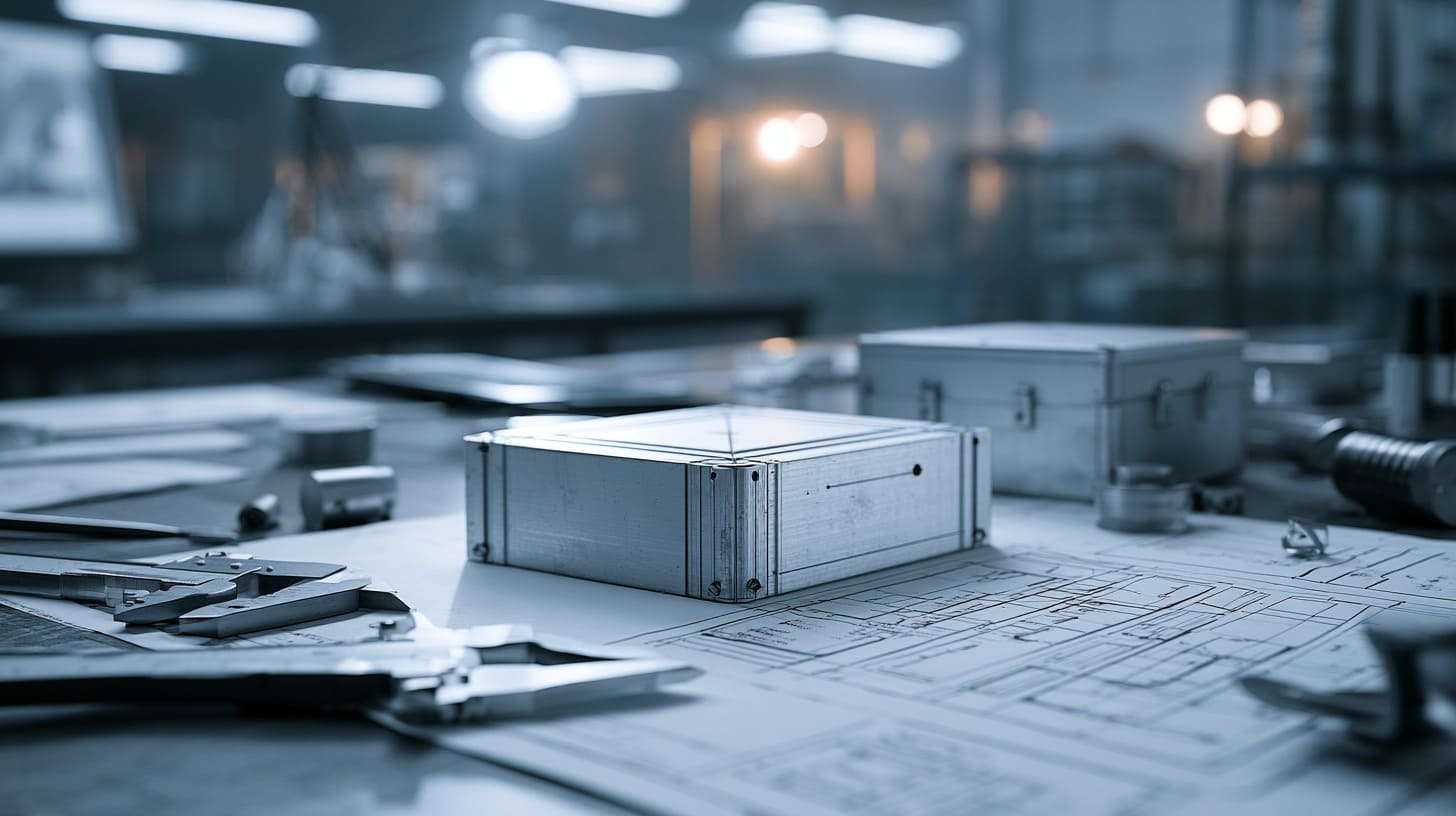
I often see a drawing come in with very strict tolerance notes. Everything looks clean on paper. Then I ask one simple question: “Did you already include coating thickness?” The answer is often no.
In one enclosure project for an outdoor controller, the customer fixed ±0.05 mm tolerance on housing walls. The problem was simple. They already planned powder coating later. The coating alone added more variation than the tolerance window.
How OEM enclosure drawings lock tolerances too early
OEM drawings often freeze tolerance before anyone talks about surface finishing. I usually slow down at this stage and check how the mechanical parts will actually be treated after machining. If this step is skipped, I already know rework will come later.
In practice, I first check whether tolerance is defined for raw machining or final coated condition, because this single detail changes the whole manufacturing strategy.
The gap between machined dimensions and coated dimensions
Machined parts and coated parts are not the same thing. But many engineers treat them as identical. This is where problems start.
| Stage | Reality | Common mistake |
|---|---|---|
| CNC machining | Accurate raw dimension | Treated as final size |
| Anodizing | Thin but uniform growth | Often ignored |
| Powder coating | Variable thickness | Not included in tolerance |
I move from this topic to real production behavior, because this gap becomes very visible once parts reach assembly stage.
Why surface finishing is often treated as “cosmetic only”
Many engineers still think coating is only for appearance. I understand this thinking, because drawings rarely show process variation.
But in real production, coating changes fit, sealing, and alignment. I usually check how the enclosure will be assembled after coating, not before coating, because this is where real functional problems appear.
What Happens to Aluminum Dimensions After Surface Finishing
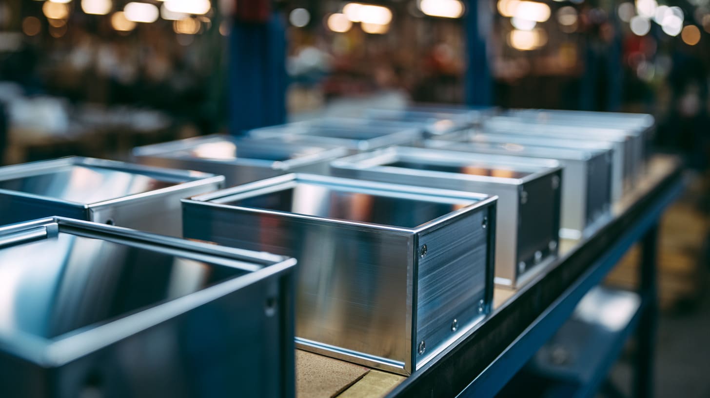
Aluminum looks stable after machining. But once surface finishing starts, dimensions slowly shift. Many buyers do not notice this until assembly fails.
A project I handled for a communication enclosure had perfect CNC parts. After anodizing, the PCB no longer aligned. Nothing changed in design, but everything changed in fit.
Material growth from anodizing and powder coating
Anodizing and powder coating both add thickness. But they behave differently.
Typical thickness ranges
| Process | Thickness | Behavior |
|---|---|---|
| Anodizing | 5–25 μm | grows into material |
| Powder coating | 60–120 μm | builds outward |
Powder coating creates more visible issues because it adds bulk outside the surface. I usually check coating type first before confirming tolerance strategy, because material growth direction changes everything.
Uneven coating distribution in real production
Coating is never perfectly even. It always behaves differently on edges, corners, and flat areas.
In one aluminum enclosure batch, corners became thicker than expected. That small change caused screw misalignment.
Common uneven patterns
- Edge build-up higher than flat surfaces
- Inner corners thinner than expected
- Masked zones slightly under-coated
This is why I never trust coating as uniform, even when supplier data looks stable.
Why Tight Tolerances Become Risky After Coating
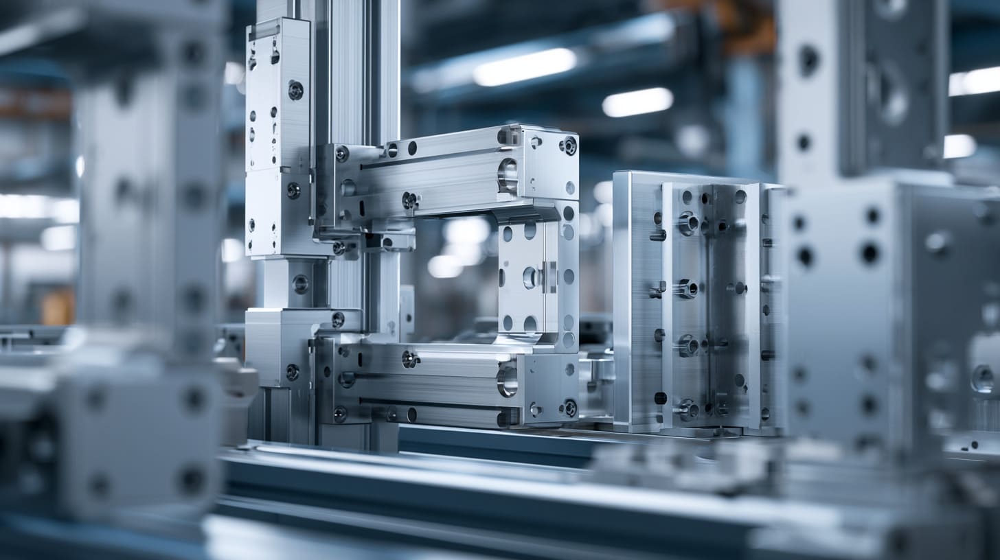
Tight tolerance sounds safe on paper. But after coating, it often becomes a hidden risk. I have seen this many times in OEM projects where assembly suddenly fails without design changes.
Stack-up tolerance problem in multi-process manufacturing
Tolerance is not one number. It is a stack of many small changes.
Main stack sources
| Process | Contribution |
|---|---|
| CNC machining | base tolerance |
| Deburring | edge variation |
| Anodizing | dimensional growth |
| Powder coating | surface build-up |
What I usually check first is the total stack-up instead of individual tolerance, because single-point thinking often hides the real risk.
The illusion of “perfect CAD fit”
CAD models look perfect. Every line fits. But CAD ignores surface layers.
One customer once sent a perfectly matched 3D model. In real life, the coated parts did not assemble. The CAD was correct. The process reality was not.
This is where things often go wrong: engineers trust digital fit too much and ignore physical layers.
Functional Risks Caused by Post-Coating Tolerance Loss
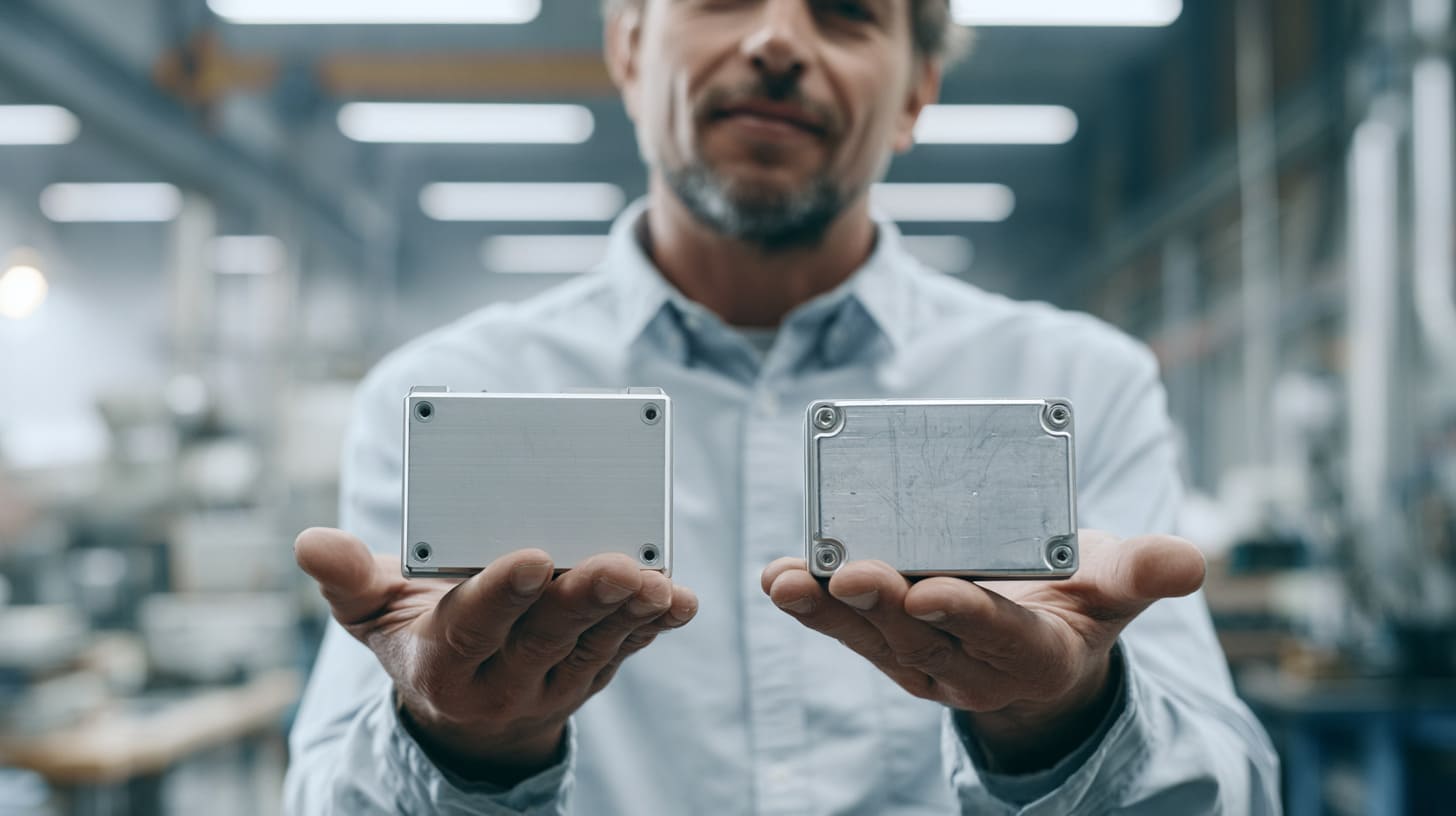
Once tolerances shift after coating, the problem is not only mechanical. It affects electronics, sealing, and long-term reliability.
A small deviation of 0.2 mm once caused a full enclosure redesign in one industrial control project I worked on.
Assembly issues in PCB and mechanical fitting
PCB alignment is very sensitive. Even small shifts matter.
Typical failure points
- PCB mounting holes no longer aligned
- Standoff stress on board corners
- Connector misfit at front panel
I usually inspect PCB fit manually in prototype stage, because digital models rarely show real assembly stress.
Sealing and IP/NEMA performance degradation
Sealing depends on compression, not just gasket presence.
| Issue | Result |
|---|---|
| Over-tight fit | gasket crush failure |
| Loose fit | leakage path |
| uneven surface | partial sealing loss |
Seal failure often comes from small dimensional shifts, not gasket design. This is something many teams underestimate.
Cost Implications of Over-Specifying Tolerances
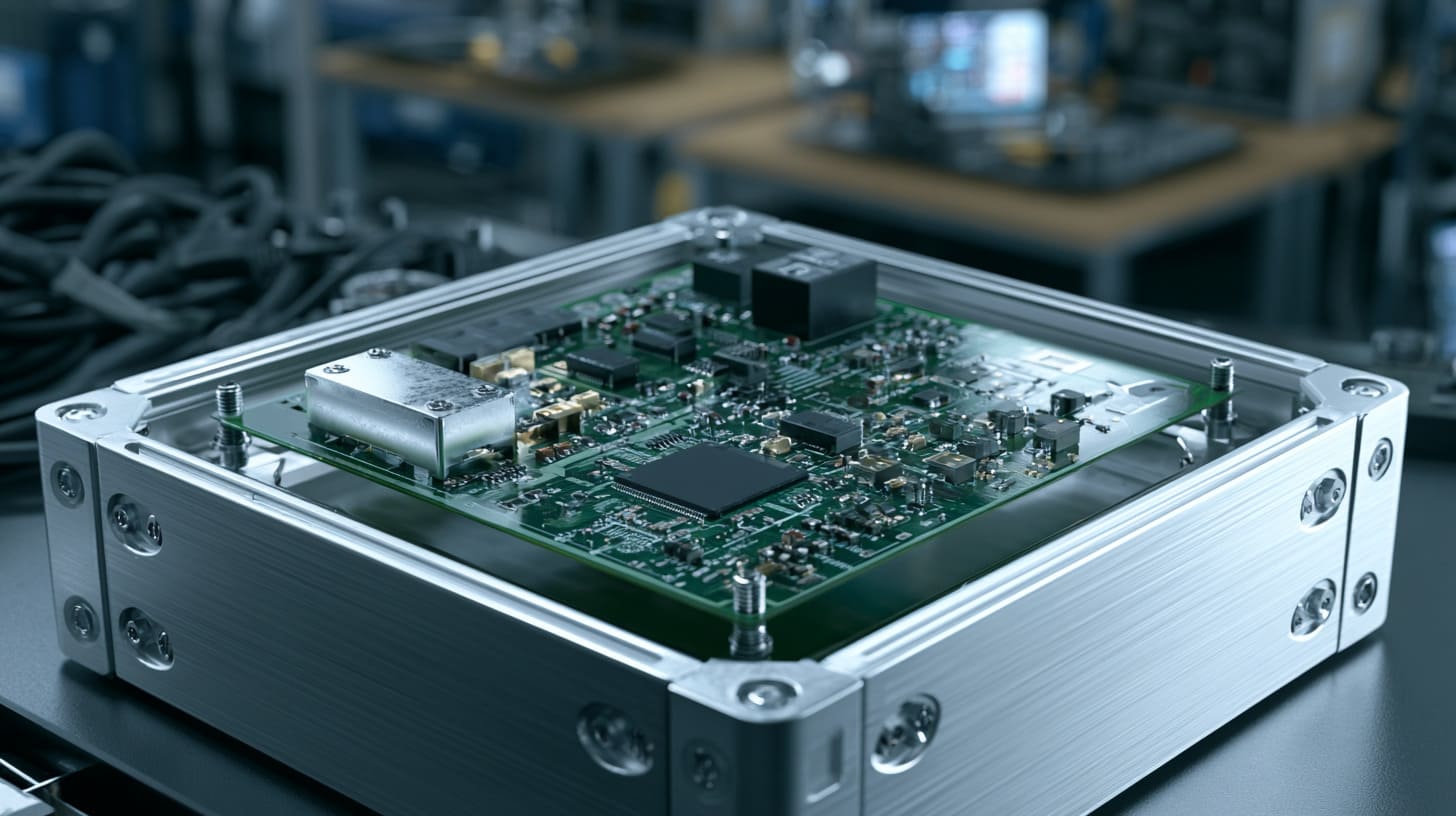
Tight tolerance increases cost faster than most buyers expect. It affects machining, inspection, and rejection.
I often see cost jump by 15–30% just because tolerance was tightened without process review.
Increased machining and rejection rates
High precision machining sounds good, but it reduces flexibility.
Cost drivers
- Slower CNC feed rates
- More tool wear
- Higher inspection frequency
This is where I usually step in and ask if tolerance really affects function, because unnecessary precision becomes pure cost.
Hidden rework and adjustment cycles
After coating, small mismatches often require manual fixing.
- Re-drilling holes
- Re-tapping threads
- Manual sanding for fit
These steps are not in the original cost sheet. But they appear in almost every over-tight project.
Engineering Trade-Offs: Precision vs Manufacturability

Not every part needs tight tolerance. But not every part can be relaxed either. The key is balance.
I have seen both extremes fail: too tight causes cost issues, too loose causes assembly failure.
When tight tolerances are actually necessary
Some areas must stay precise.
- RF shielding contact zones
- PCB critical mounting points
- Connector alignment interfaces
I usually isolate only these zones for tight control, because applying precision everywhere is unnecessary.
When relaxed tolerances improve product stability
Non-critical areas benefit from flexibility.
- Outer enclosure surfaces
- Decorative panels
- Non-contact structural walls
This is where I often suggest relaxing tolerance, because it improves yield and reduces stress in production.
How to Design Tolerances for Coated Enclosures
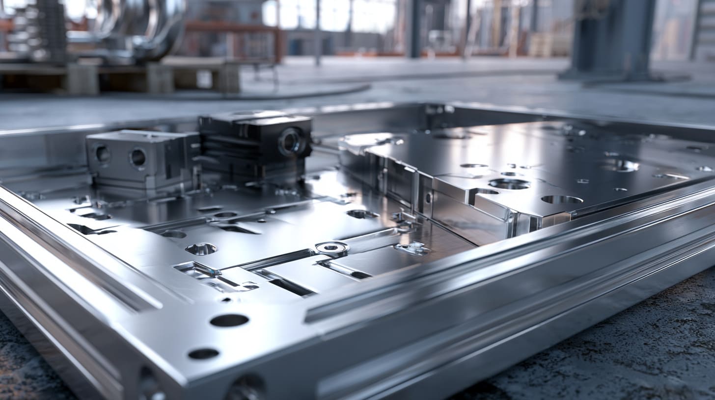
Good tolerance design always includes coating from the start. Not after.
A project becomes stable when engineers think in two layers: before coating and after coating.
Best practices before surface finishing
Key principles
- Separate pre-coating and final dimensions
- Define coating thickness allowance early
- Avoid one-layer tolerance thinking
I usually mark drawings with coating zones before confirming machining tolerance, because this prevents misunderstanding later.
Collaboration between design and factory
Engineering decisions cannot stay on paper.
| Stage | Action |
|---|---|
| Design | define tolerance strategy |
| Sample | test coating effect |
| Pilot run | verify assembly fit |
I usually push for prototype validation, because real coating behavior often surprises even experienced teams.
Industry Mistakes Seen in OEM Aluminum Enclosures
Most tolerance problems are not technical mistakes. They are communication mistakes between design and production.
Over-engineering without process understanding
Some drawings look perfect but ignore production reality.
- Copying tight tolerances from machined parts
- Ignoring coating variability between suppliers
- No discussion with factory engineers
This is where I usually pause and re-evaluate the whole design logic before production starts.
Case-driven failure patterns
I have seen repeating failure patterns across many projects.
- Enclosures misaligned after powder coating
- Gasket compression failure in field use
- Assembly force higher than expected
These are not random issues. They come from the same root: tolerance not aligned with process.
Conclusion
The real cost is not tolerance—it is redesign and delay
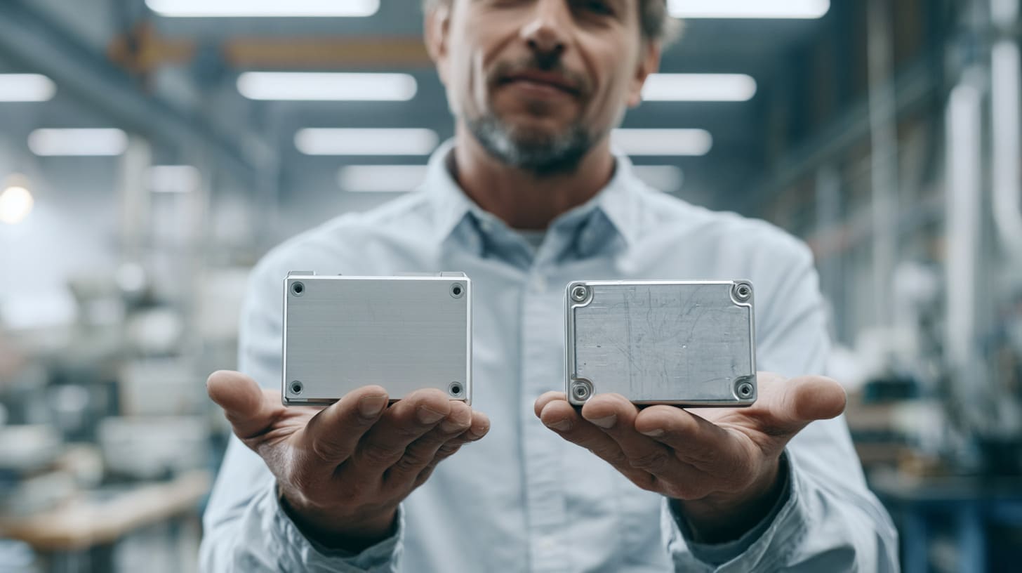
I don’t treat tolerance as a drawing number. I treat it as a production decision. Once coating is included, everything changes: fit, sealing, and assembly behavior.
This is why I always push to define coating first, then tolerance. Not the other way around.
In practice, I focus on where the enclosure actually touches real stress, because unnecessary precision outside functional zones only increases cost without improving performance.
If someone asks me why I insist on this approach, the answer is simple. I have seen too many projects delayed not because of design mistakes, but because tolerance was defined without thinking about surface finishing.
If you are working on OEM enclosure design, I suggest reviewing your drawings from this angle again. It often reveals hidden cost and risk that are easy to miss on paper.