

The first enclosure sample can look excellent: even black color, clean machining and a lid that closes neatly. Then the team discovers that a connector flange, bonding point or lid seam was anodized along with everything else. The appearance passed inspection, but an intended electrical interface may not work as designed.
Anodizing is useful for aluminum enclosures. Its oxide layer can provide an attractive, protective surface, but that layer is electrically insulating. Where an EMC design depends on contact between metal parts, the finish needs its own plan. The issue is not simply whether the enclosure is aluminum; it is where current is intended to flow and what lies between the mating surfaces.
In my experience, the expensive mistake is ordering a finish before identifying those interfaces. A small finish map can prevent a much larger argument after the sample returns from the test lab.
Find the Interfaces That Need Conductivity
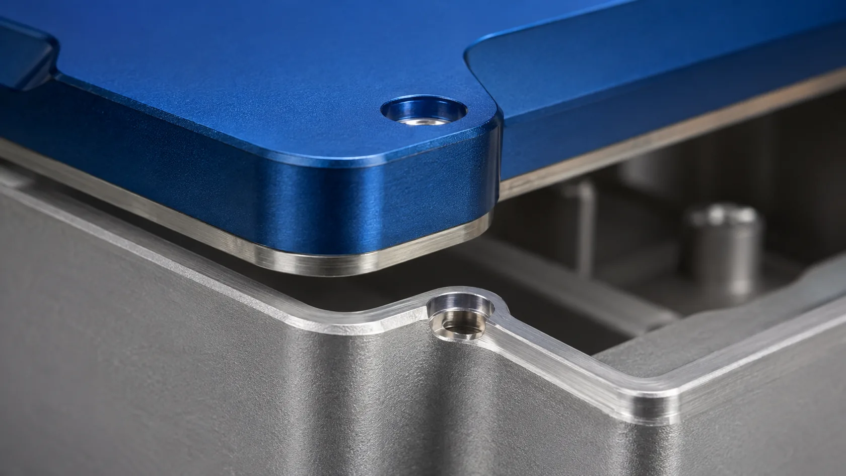
Map the actual electrical paths
Start with the assembled product, not an isolated extrusion or cover. Mark the surfaces that must make electrical contact, the mating component and the purpose of each contact. The European Commission's EMC guidance describes electromagnetic compatibility in terms of equipment operating without unacceptable electromagnetic disturbance; a metal box alone does not establish that outcome.
| Interface | Question to settle before finishing |
|---|---|
| Protective earth attachment | What approved connection and verification does the product safety design require? |
| Lid-to-body seam | Does the shielding design need a continuous contact path or a qualified gasket? |
| Connector flange and cable shield | How does the connector terminate the shield to the housing? |
| Internal chassis or bracket | Is this a structural mount, an electrical bond, or both? |
A protective-earth bond and an RF seam serve different purposes. A continuity reading at one screw may show a connection while leaving gaps along a lid seam. I ask the product engineer to identify both the safety path and the intended EMC current path; a finish supplier should not be left to infer either from the word “ground.”
Once those locations are visible on the drawing, the finish can be selected around them.
Choose a Finish Strategy Before Quoting
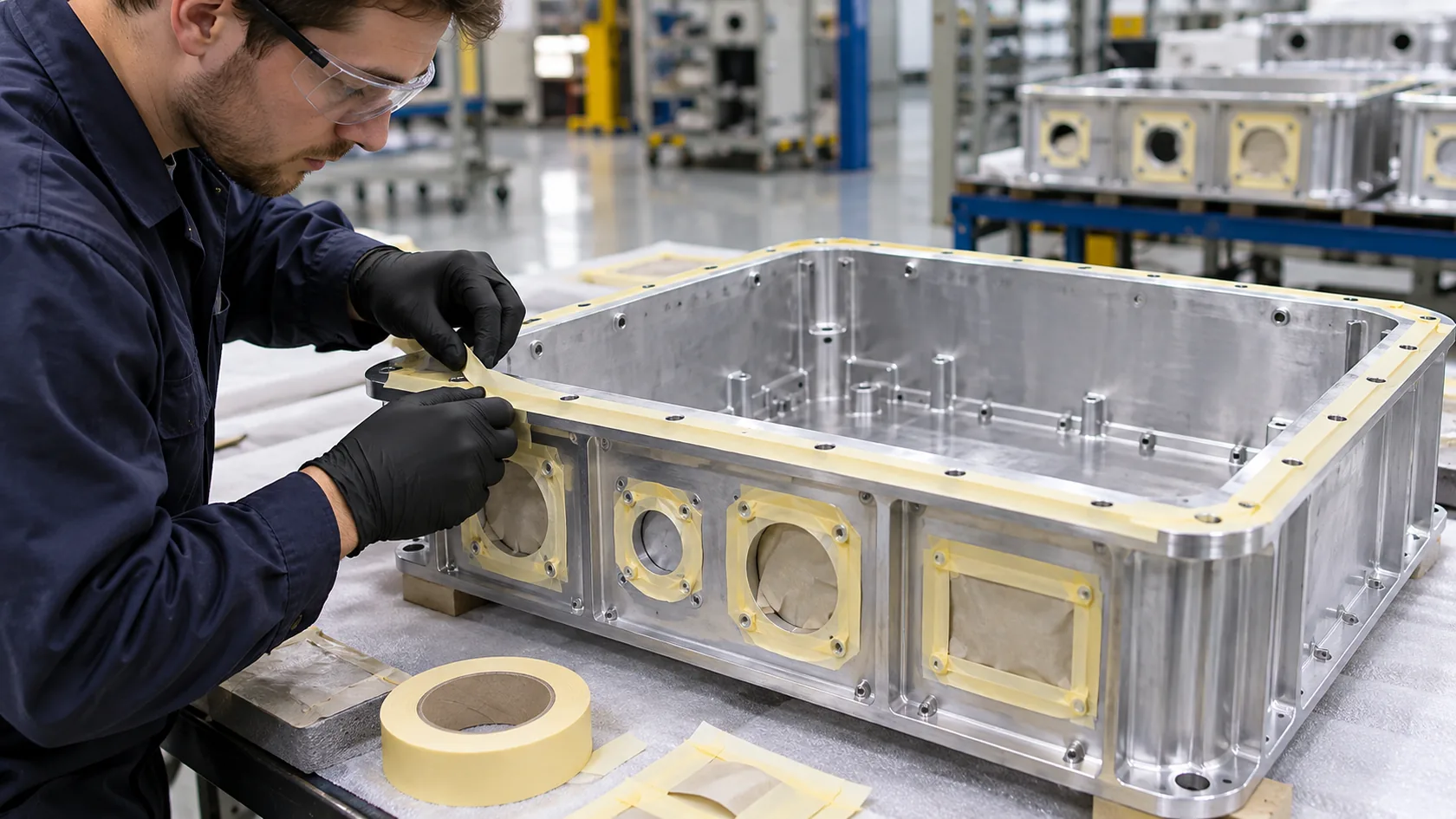
Compare the practical routes
| Approach | Useful when | Production question |
|---|---|---|
| Mask contact lands before anodizing | Contact areas are accessible and boundaries can be controlled | How will mask placement, edge quality and the final surface be inspected? |
| Use a specified conversion coating on contact areas | A compatible low-contact-resistance surface and corrosion protection are needed | Which qualified chemistry, specification, process sequence and acceptance method apply? |
| Machine selected lands after anodizing | A precise surface or boundary is needed and access permits | How will the part be held without damaging the finish, and how will exposed metal be protected? |
| Select another finish system for the part | Many surfaces need electrical contact or masking becomes impractical | Does the alternate finish meet appearance, exposure and electrical requirements? |
Conversion coatings are not interchangeable. If a drawing invokes MIL-DTL-5541, specify the applicable revision, type and class with the finisher and confirm project restrictions on coating chemistry. Even a suitable coating and assembly need validation; “conductive finish” is not a guarantee of a particular joint resistance.
Bare aluminum also develops a natural oxide and can corrode in service. A masked patch is therefore not a complete protection strategy. I would rather see a clearly defined contact treatment and acceptance method than a drawing note saying only “leave metal exposed.” Confirm the proposed order of operations with the finisher: masking, anodizing, local treatment and post-machining may interact.
That decision changes both the quote and the way the enclosure must be assembled.
Make the Seam Work as an Assembly
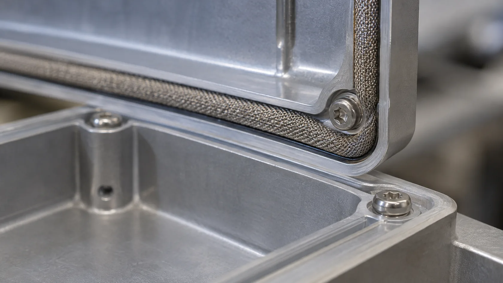
A gasket still needs a usable contact surface
A conductive gasket can bridge a seam when the design calls for it, but it does not automatically solve an insulating coating or a warped flange. Contact surface condition, gasket material, compression, fastener spacing and lid stiffness all matter. Parker Chomerics' shielding guidance emphasizes the importance of conductive peripheral contact at mating flanges.
Agree on a gasket track wide enough for the selected gasket and its manufacturing tolerances. Check the actual compressed height, stops and fastener arrangement with the gasket supplier. If the design uses coating-penetrating contacts, qualify that exact contact system; do not assume every spring or washer will break through anodizing reliably after repeated service.
Outdoor designs add another trade-off. Water, condensation, dissimilar metals and trapped moisture can damage a contact interface. A conductive gasket and an environmental seal may have different material and compression requirements. I check the entire stack with the intended fasteners, seal, drainage and maintenance access rather than treating either gasket as a complete solution.
The next step is to prove that the intended interface survives real production and use.
Verify the Finished Production Configuration
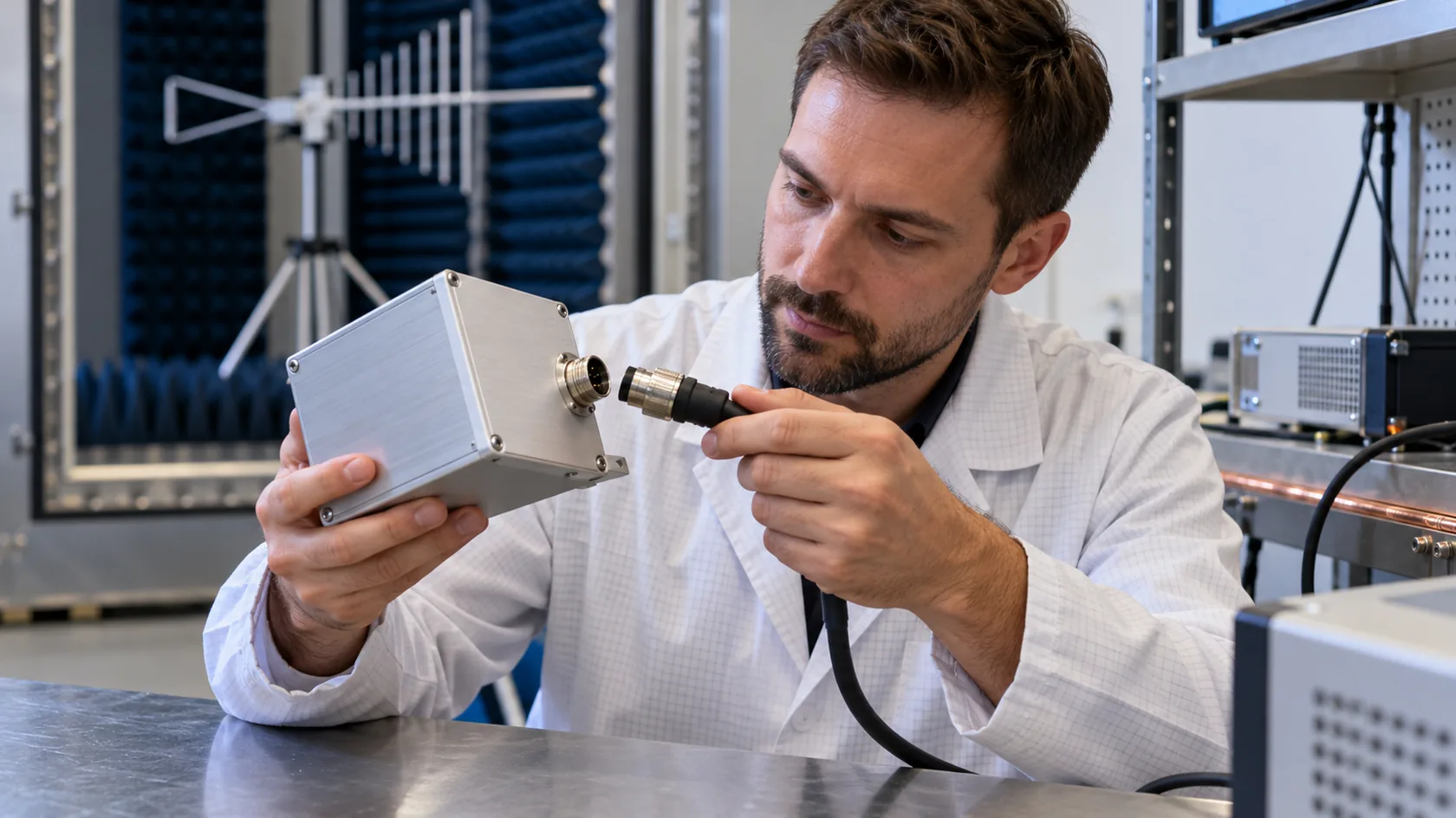
Put acceptance criteria on the drawing
Mark contact land locations and boundaries, finish and masking requirements, mating parts, assembly hardware, torque where applicable, and cosmetic limits. Define who inspects the lands and how the supplier records the result. If joint resistance is required, specify the method, instrument, probe locations, assembly condition and project-specific acceptance limit; a value cannot be chosen responsibly without the design and safety requirements.
For first articles, check finish coverage, masking position and mating fit on representative parts. Then assemble the real lid, gasket, connectors, cable shields and hardware. Include service cycles, corrosion or environmental exposure when relevant to the installation and the product's qualification plan. A sample with temporary wires and a different lid may not represent production.
DC continuity is useful for finding an open bond, but it is not a substitute for radiated emissions or immunity testing. The responsible product team should test the representative finished apparatus to its applicable requirements. The FCC equipment authorization guidance explains that applicable authorization and testing requirements depend on the equipment and rules.
From a factory perspective, repeatability matters as much as the first successful sample: keep the finish map, assembly instructions and inspection record under revision control when moving to volume production.
Conclusion

I have found that anodizing becomes a problem when a cosmetic instruction quietly covers an electrical requirement. The solution is usually a more precise finish and assembly specification, not a blanket rejection of anodizing. The right choice depends on the contact path, exposure, manufacturing sequence and the finished product's test plan.
Before requesting the next quotation, mark the lid seam, connector interfaces and safety bonding points on the drawing. A short review with the enclosure supplier and finishing shop can reveal whether the proposed contact lands are accessible, protectable and repeatable before the first sample is made.