Skip to content
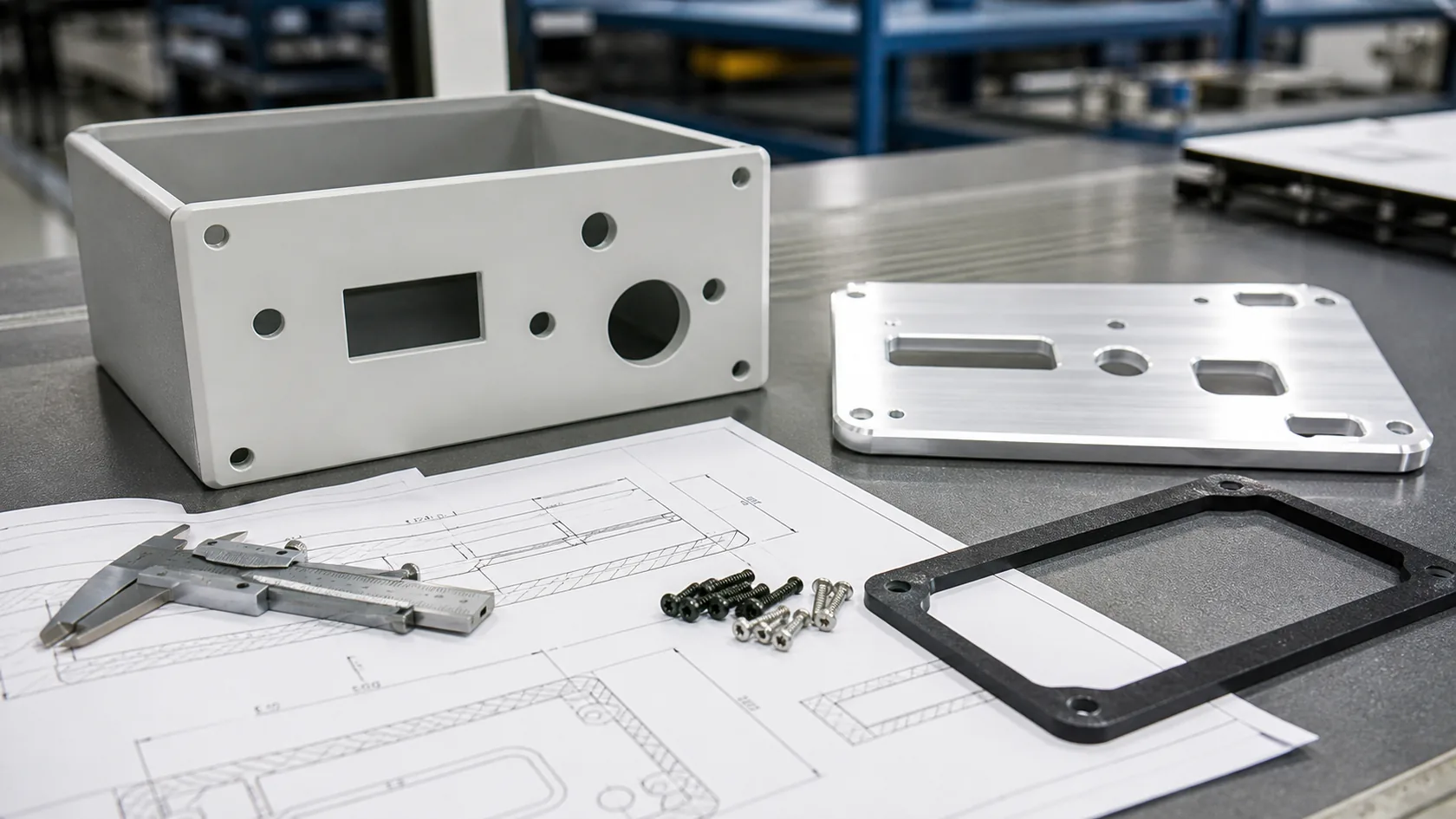
Coating thickness sounds like a small detail until the finished parts stop fitting.
Before finishing, a cover slides smoothly. A screw enters nicely. A gasket sits flat. A connector fits the opening. Then the parts come back from powder coating, anodizing, painting, or plating, and suddenly the assembly line becomes a little circus. The lid is too tight. The screws feel rough. The gasket is squeezed too much. The buyer asks why the tolerance changed.
The answer is often simple: the drawing controlled the metal part, but not the finished part.
In our factory, I see this most often on custom aluminum enclosures, sheet metal housings, CNC covers, brackets, and tight electronics assemblies. Buyers focus on machining tolerance or bending tolerance, which is important. But if the product needs a surface finish, the final functional size includes the finish.
My rule is practical: if a surface touches, slides, seals, screws, grounds, or fits another part, coating thickness must be part of the design conversation. If we ignore it, the cost does not disappear. It moves into rework, sorting, delayed shipment, damaged finish, and uncomfortable emails.
This article explains the hidden cost of ignoring coating thickness in tight-tolerance assemblies, and how buyers can prevent it before production starts.
Why Coating Thickness Becomes an Assembly Problem
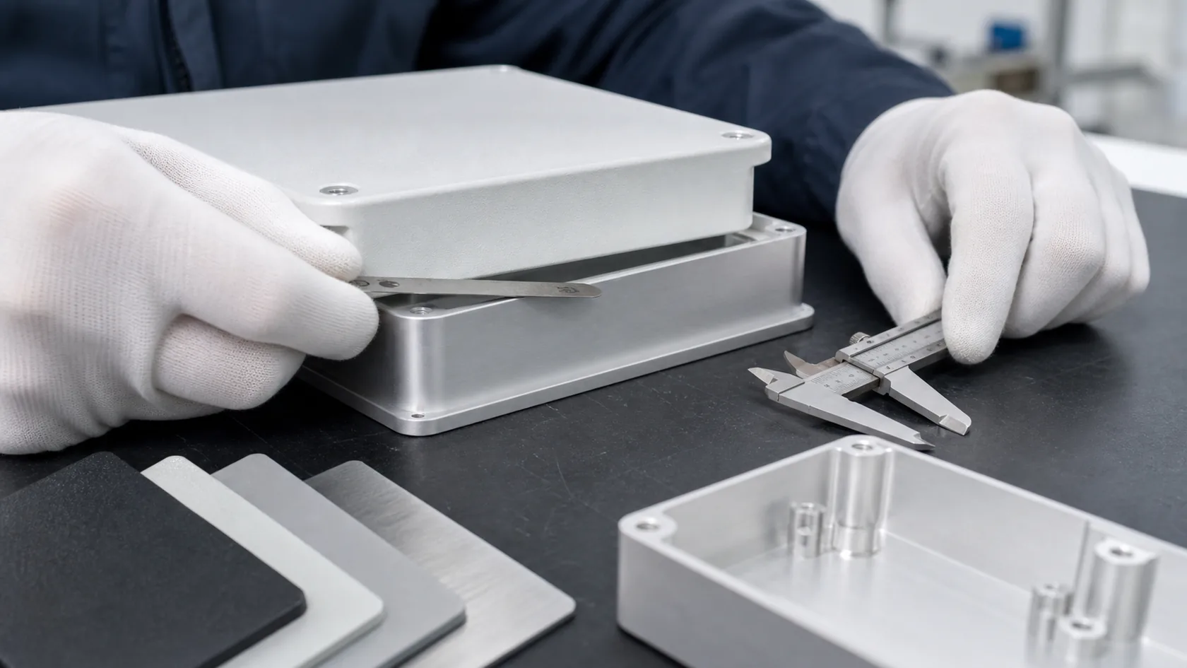
A finish is not only color. It is material added to, grown on, or bonded with the surface. That means it can change the real size and behavior of the part.
The finish changes functional dimensions
Powder coating adds a separate coating layer on the surface. Wet paint and e-coating also add film. Anodizing creates an oxide layer on aluminum. Plating adds metal. Conversion coating is usually very thin, but it still has a functional purpose.
The problem appears when the drawing dimension is checked before finishing, but the product is used after finishing. A hole, slot, groove, or mating face may look correct on paper and fail in real assembly.
Small buildup can happen twice
Many assemblies have two finished surfaces touching each other. If a powder-coated lid fits into a powder-coated base, the coating exists on both sides. That means the clearance loss can be double-sided.
For tight electronics enclosures, this matters more than many buyers expect. A 0.10 mm issue in one place may be harmless. A 0.10 mm issue on both mating parts, plus tolerance stack-up, plus a little corner buildup, can create a very real assembly fight.
Corners and holes behave differently
Coating thickness is not always perfectly even. Edges, corners, recessed areas, blind holes, threaded holes, and slots can behave differently from flat panels. Powder coating may build up at corners or leave thinner coverage in deep pockets. Anodizing and plating also depend on geometry and process control.
I usually ask buyers to show me the surfaces that must fit after finishing. A general note like "black powder coat" is not enough when the part has tight slots, sliding rails, or connector openings.
Once the finish becomes part of the functional size, the drawing needs to say what is measured and when.
The Drawing Mistake: Specifying Raw Size Only
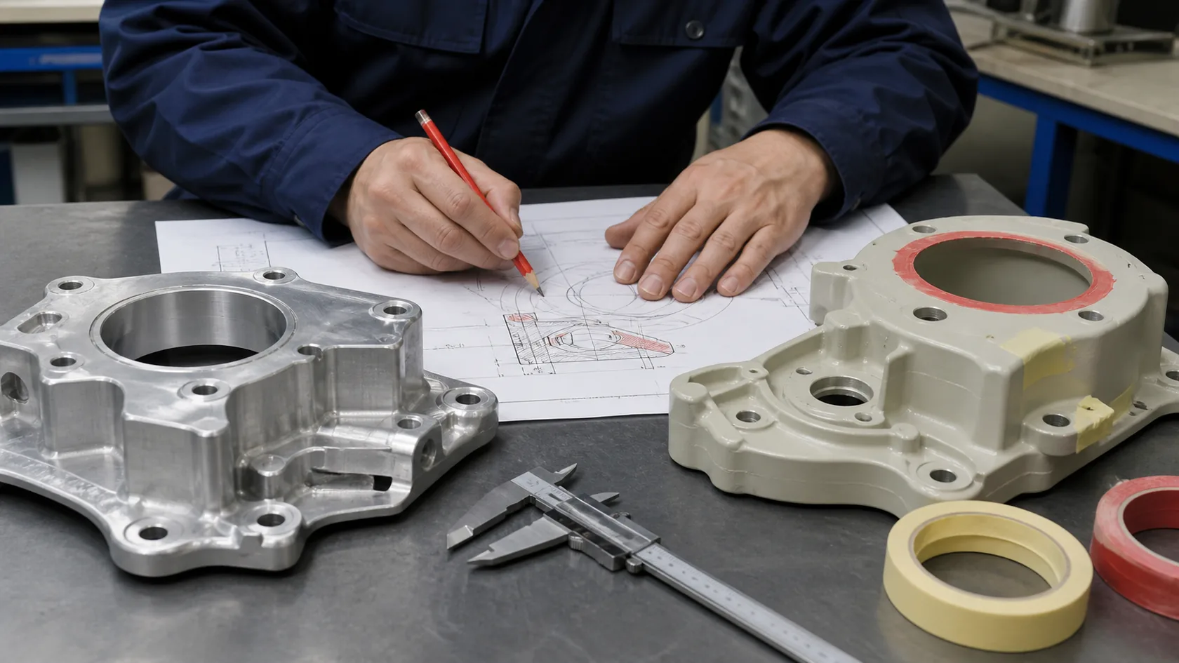
The most expensive coating thickness mistake often starts with a clean drawing. The drawing may be technically nice, but it controls only the raw metal geometry.
Raw part tolerance is not final assembly tolerance
If the drawing says a slot is 10.00 +/- 0.05 mm, does that mean before coating or after coating? Many buyers assume the supplier knows. Many suppliers assume the note means raw metal unless the drawing says otherwise. This is how two reasonable people create one unreasonable batch of parts.
For tight-tolerance assemblies, buyers should mark critical dimensions as:
- before finishing
- after finishing
- finish-free / masked
- reamed after finishing
- tapped after finishing
- acceptable with coating buildup
This is not over-engineering. It is cheaper than asking an operator to file 1,000 parts by hand while everyone pretends this was not predictable.
Functional areas need special notes
Some dimensions are cosmetic. Some are functional. A small thickness change on a visible outside wall may not matter. The same change inside a board slot, gasket groove, thread, hinge pin hole, or sliding rail can stop the product.
Useful drawing notes include:
- "Mask this grounding pad before coating."
- "Thread must be clean after finish."
- "Dimension applies after coating."
- "Gasket land must remain flat and free of heavy buildup."
- "Connector opening must meet final size after finish."
- "Sliding rail clearance checked after anodizing."
When I quote a project, I look for these notes before I look at the pretty surface sample. Pretty is nice. A cover that closes is nicer.
The next hidden cost appears when the supplier must fix problems after coating.
Rework After Coating Is Not Cheap
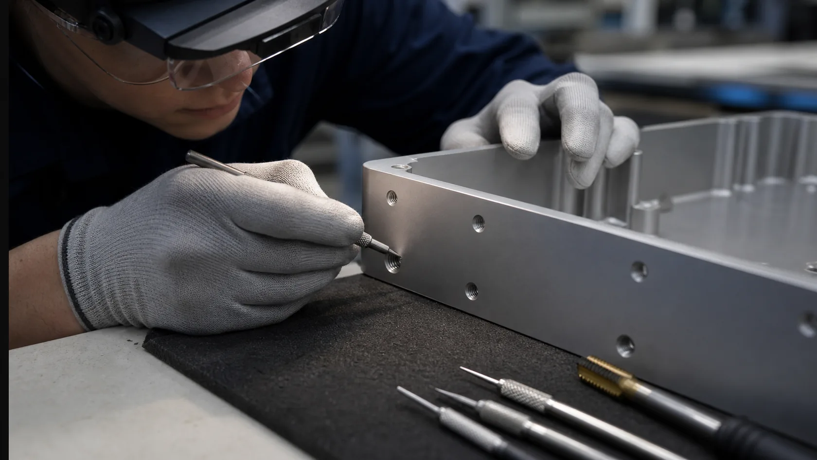
Rework before finishing is one kind of cost. Rework after finishing is a different animal. It is slower, riskier, and easier to make ugly.
Post-finish machining can damage the surface
If holes are too small after coating, one solution is to drill, ream, or tap again. Sometimes this is acceptable. But it can chip powder coating, expose bare metal, leave burrs, or create visible marks around a cosmetic area.
For anodized parts, post-finish machining removes the anodized layer in that area. That may be fine for a hidden functional hole. It may be unacceptable on a visible face or corrosion-sensitive edge.
Hand fitting adds labor and inconsistency
Hand filing, scraping, cleaning threads, and forcing parts together can rescue a small batch. It is not a good production plan. One operator may remove too much. Another may remove too little. The final result can vary from part to part.
This is why coating thickness problems feel so expensive. The unit cost of the finish may not be high, but the hidden labor after finishing can destroy the schedule.
Rework can create second-order problems
A fixed hole may now have exposed metal. A cleaned thread may lose corrosion protection. A filed sliding surface may look uneven. A forced screw may damage the surrounding finish. The first problem gets solved, then a smaller but uglier problem appears.
In real work, I prefer changing the design or masking plan before finishing instead of creating a rework plan after finishing. Rework is useful as an emergency tool, not as a sourcing strategy.
The painful part is that many of these problems are easy to prevent with the right critical-area review.
Threads, Holes, Slots, and Sliding Fits
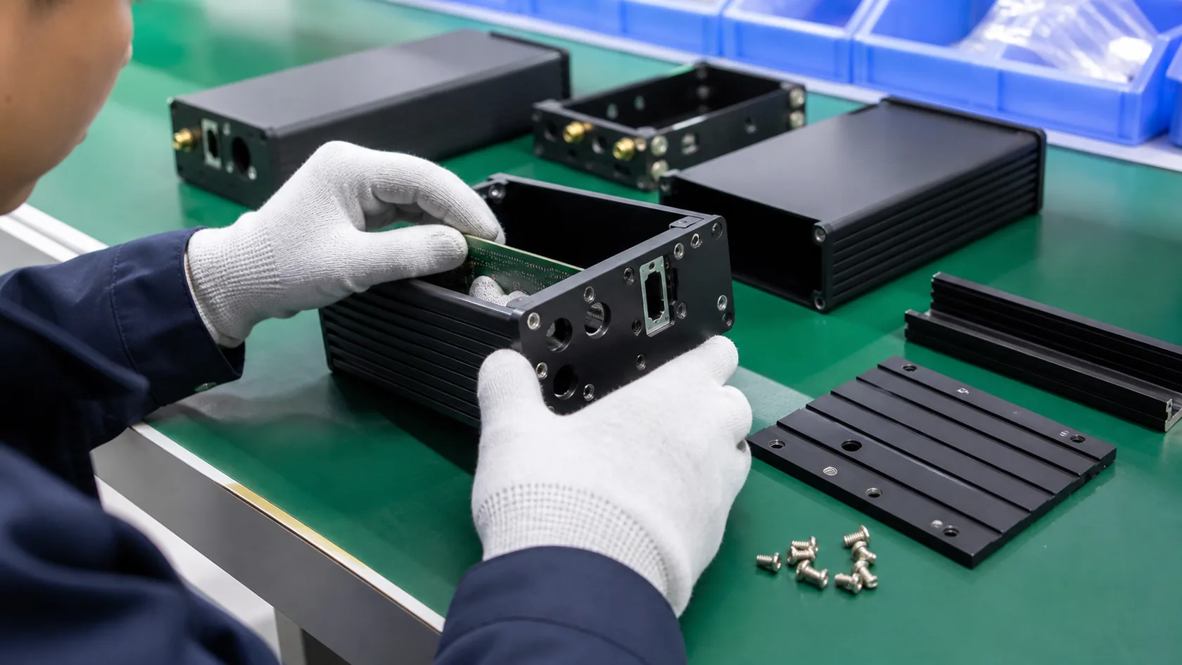
The places most affected by coating thickness are usually not the large flat surfaces. They are the small functional features.
Threads and inserts
Threads are sensitive because coating can reduce clearance. Powder coating can fill threads or leave material at the thread entrance. Anodizing can affect thread fit, especially with tighter requirements or thicker hardcoat anodizing.
For sheet metal enclosures with PEM inserts, coating can also collect around insert edges. This can affect screw seating or make the surrounding surface look rough.
The buyer should decide whether threads are:
- masked before finishing
- cleaned after finishing
- tapped after finishing
- accepted with the finish
- protected with plugs or caps during coating
Holes and connector cutouts
USB ports, cable glands, switches, displays, hinges, and latch openings all have final fit requirements. A coating that reduces the opening slightly may cause field assembly issues.
For example, a cable gland hole in raw aluminum may pass inspection. After powder coating, the gland may not pass through smoothly. The operator may push harder, twist harder, and damage the edge. Nobody enjoys that little opera.
Slots and sliding rails
Board slots, removable covers, rail features, and sliding panels are especially sensitive. Coating on both sides of a slot can reduce usable width. If the rail also has coating, friction increases.
I check sliding features by asking how many times the buyer expects the part to move. A one-time assembly fit and a daily-use sliding cover are not the same problem.
Functional features need clear finish strategy. Sealing and grounding areas need it even more.
Gasket, Grounding, and Contact Surfaces
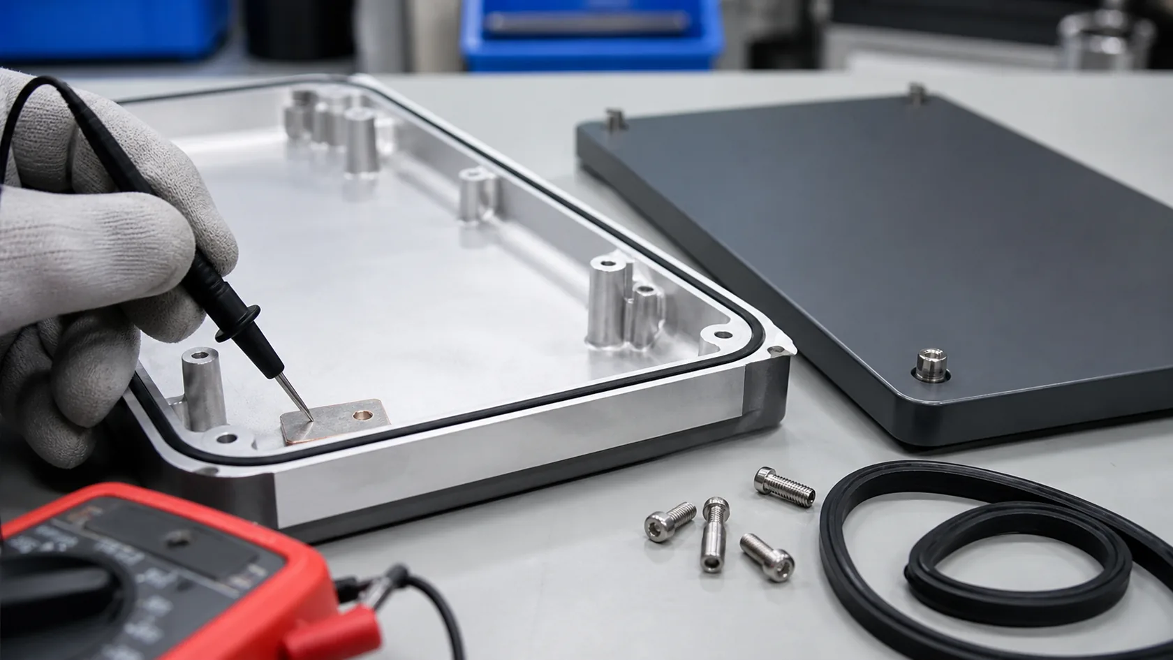
Coating thickness is not only about size. It also affects sealing, electrical contact, and surface behavior.
Gasket compression depends on final geometry
A gasket needs controlled compression. If coating buildup changes the groove depth, flange height, or sealing face, the gasket may be too loose or too tight. Too loose can leak. Too tight can deform the gasket or make the cover difficult to close.
Powder coating texture can also affect the sealing face. A rough texture may be acceptable for a general cover, but not always for a sealing surface.
Grounding surfaces may become insulated
Powder coating usually insulates the metal surface. Anodizing creates an oxide layer, so it can also reduce surface conductivity. Clear anodizing may look like bare metal, but it is not the same as a raw aluminum grounding contact.
For grounding and EMI contact areas, the drawing should define bare pads, masked areas, conductive treatment, or post-finish cleaning. Standards such as ASTM B449 discuss chromate conversion coatings on aluminum for corrosion protection, paint base, and low electrical contact impedance, which is useful context for functional contact surfaces.
Fastener seating surfaces can chip or compress coating
Screw heads, washers, standoffs, and nuts press against the finish. If the coating is thick or soft, the fastener may settle over time. If the operator uses too much torque, the finish can crack or chip around the screw.
I like to define whether the surface under a screw head is cosmetic, conductive, or only mechanical. One screw location can have three different meanings, and guessing is where small parts become loud.
After identifying functional surfaces, the next step is controlling and measuring the finish.
Measuring Coating Thickness the Practical Way
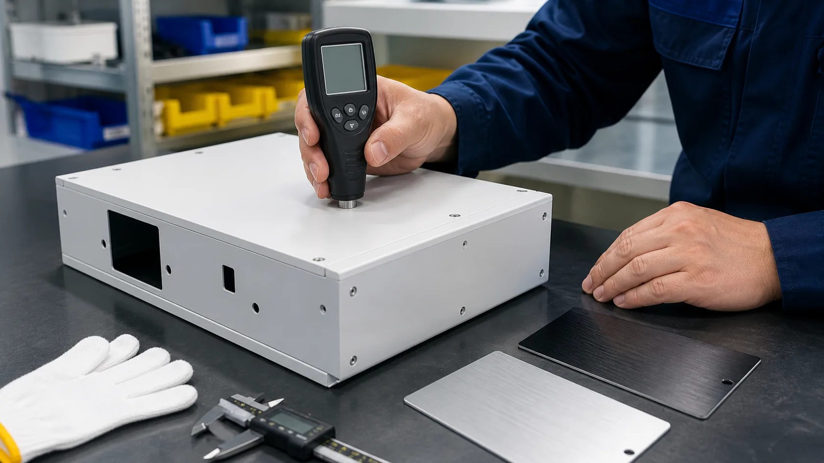
If coating thickness affects assembly, it should be measured in a useful way. Not every surface needs laboratory-level control, but critical surfaces need a real inspection plan.
Use the right measurement method
For nonmagnetic coatings on metal, dry film thickness is often checked with suitable gauges. ASTM D7091 is a common reference for nondestructive dry film thickness measurement on coated metals. The useful idea for buyers is simple: define where to measure, how many points to check, and what range is acceptable.
For anodizing, thickness control depends on the anodizing type and specification. Decorative anodizing, hardcoat anodizing, and special functional anodizing should not be treated the same way. Hardcoat in particular needs attention because it can affect wear and dimensions.
Measure where assembly happens
A flat outside wall may be easy to measure, but it may not be the problem area. The critical location may be a flange, slot, rail, hole edge, or gasket surface. Those areas can be harder to measure, but they are also where failure happens.
If a measurement point is impossible, use a test coupon or sample area that represents the process. This is common sense factory control, not fancy paperwork.
Do not specify impossible requirements
Buyers sometimes ask for very tight metal tolerances, thick coating, perfect cosmetic appearance, no masking marks, and low cost in the same sentence. I admire the optimism. I do not recommend building a production plan on it.
A good supplier should tell you when coating thickness and tolerance are fighting each other. The earlier that conversation happens, the cheaper it is.
Measurement helps, but good design decisions help even more.
How to Design Around Coating Thickness
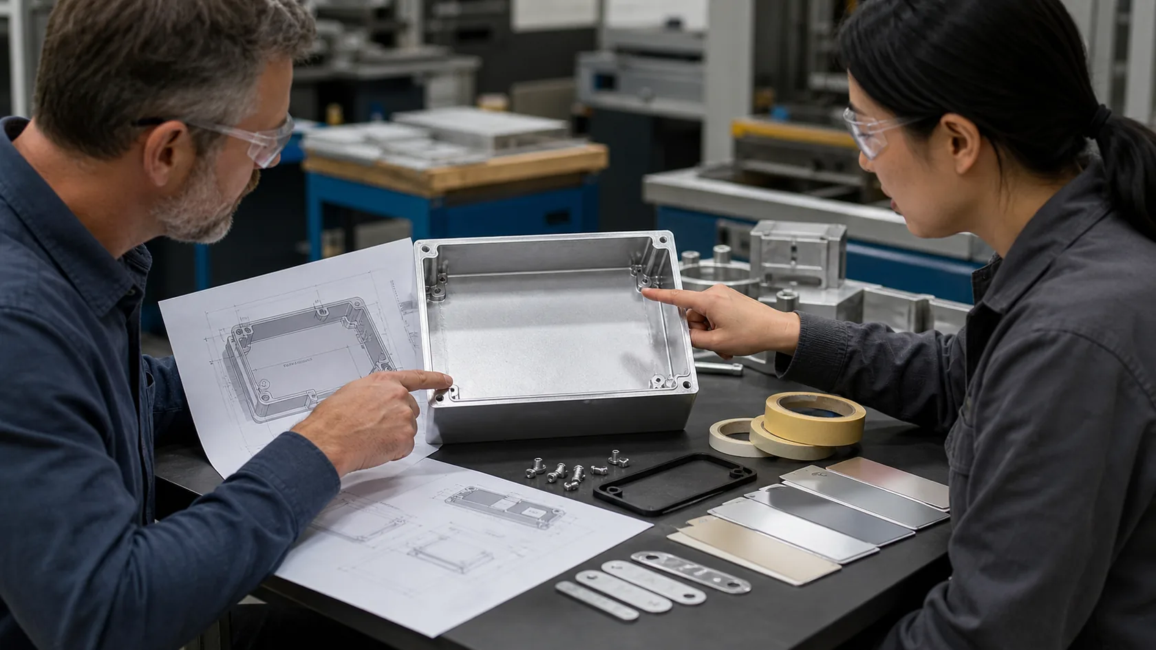
The best way to control coating thickness cost is to design the assembly with finishing in mind.
Add clearance where coating is expected
If two coated surfaces fit together, allow for the finish on both sides. The exact allowance depends on the finish type and specification. A powder-coated assembly usually needs more clearance than an anodized one.
For tight covers, rails, and slots, it is wise to test with a finished sample before approving mass production. A raw prototype can confirm geometry, but a finished prototype confirms reality.
Mask or machine critical areas
Some areas should not be coated. Some should be finished first and then machined. Some should be coated and then cleaned. The correct sequence depends on the feature.
Common strategies include:
- masking threaded holes
- masking grounding pads
- keeping gasket lands smooth
- machining critical holes after finish
- using plugs in coating-sensitive holes
- approving rack and mask mark locations
- checking sample assembly before bulk production
Separate cosmetic and functional surfaces
Cosmetic surfaces should look good. Functional surfaces should work. Sometimes one surface must do both, and then the risk goes up. When possible, design the product so visible areas and tight functional areas are not fighting each other.
My favorite drawings make this easy to see. They mark finish, masking, and critical final dimensions directly. There is less romance, more clarity, and fewer emergency phone calls.
Before sending the RFQ, buyers can use a short checklist.
A Buyer Checklist Before Approving the Finish
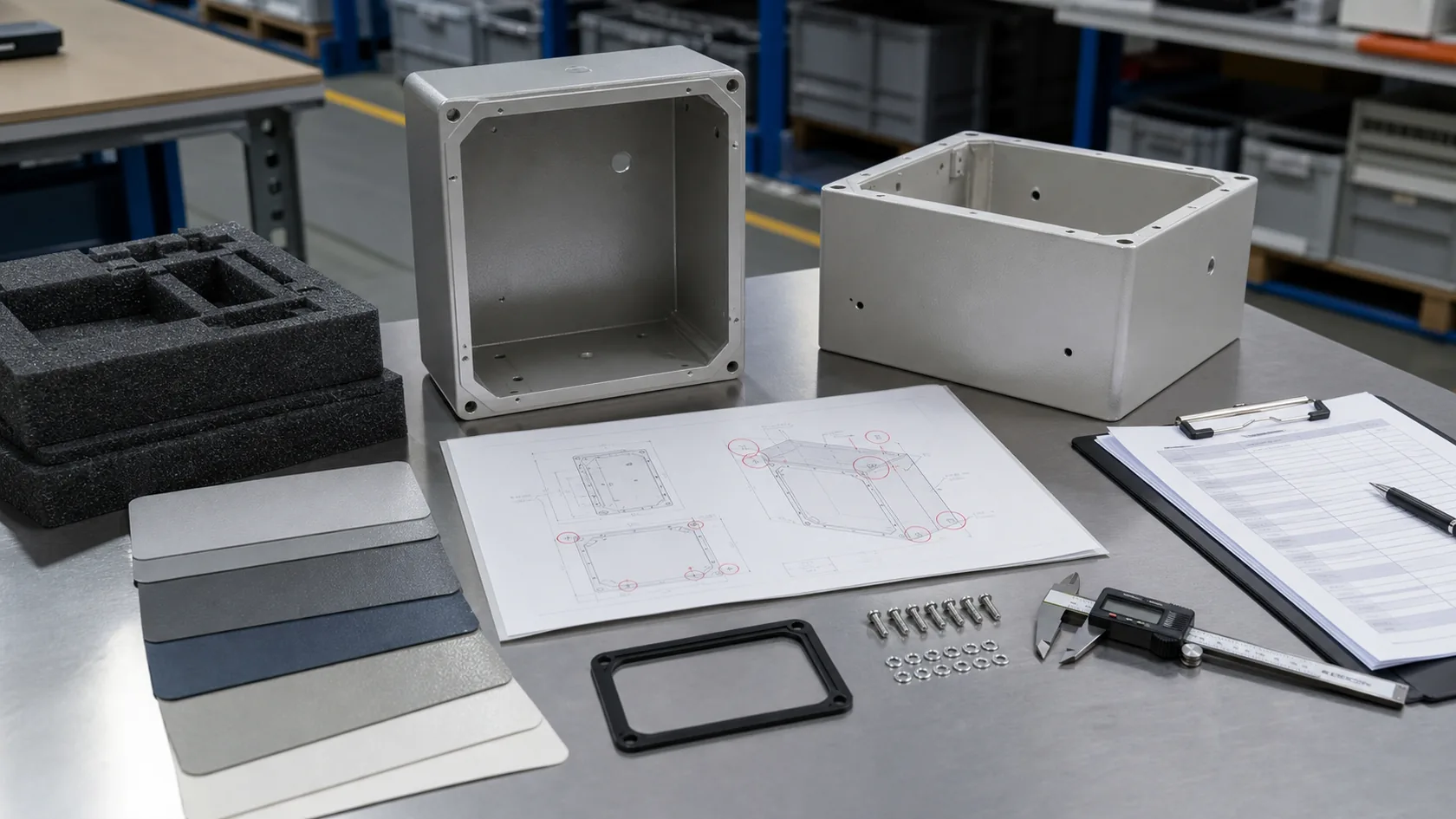
Before you approve powder coating, anodizing, painting, plating, or any other finish for a tight-tolerance assembly, ask a few direct questions.
Critical questions
| Question | Why it matters |
|---|---|
| Which dimensions are checked after finishing? | Raw part size may not reflect final assembly fit. |
| Which surfaces touch another part? | Coating on both sides can reduce clearance. |
| Which holes, slots, or threads need masking? | Coating can block or tighten small features. |
| Where does a gasket seal? | Coating texture and buildup can affect compression. |
| Where does grounding happen? | Many finishes reduce electrical contact. |
| Where are rack marks allowed? | Holding points can leave small marks. |
| Is a finished sample required? | Raw samples do not prove finished assembly. |
| How is thickness measured? | Inspection must match the real risk area. |
What to send the supplier
For a smoother quote and fewer surprises, send:
- 2D drawing with finish notes
- 3D file
- surface finish requirement
- use environment
- assembly method
- critical dimensions after finish
- masking areas
- approved sample or color target
- testing or inspection requirement
If a buyer sends only a 3D model and a color name, I can still quote. But if the assembly is tight, I will ask questions. A good question before production is not a delay; it is a small insurance policy.
This checklist will not remove every manufacturing risk, but it removes many of the silly ones. The silly ones are my personal enemy.
Conclusion
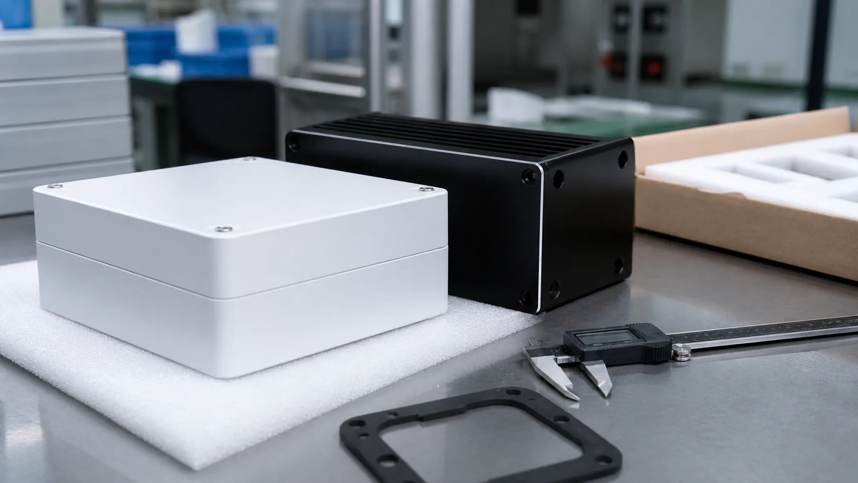
Ignoring coating thickness is expensive because it hides inside normal-looking parts. The finish may look beautiful, the raw dimensions may pass inspection, and the batch may still fail during assembly.
The real cost shows up as tight lids, blocked threads, poor gasket fit, damaged coating, lost grounding contact, sorting labor, rework, late shipment, and uncomfortable project discussions. None of these costs feel like "surface finishing cost" at first, but that is exactly where they started.
My advice is simple. Do not treat coating thickness as an afterthought when the assembly is tight. Mark functional surfaces. Decide what is measured before and after finishing. Define masking. Approve finished samples. Check the assembly in the same condition the customer will use it.
At MaidaTech, we help buyers review enclosure drawings before finishing so the product looks right and still fits after coating. If your project has tight slots, threads, gasket faces, grounding pads, or sliding parts, send us the drawing and finish target. We can help you catch the hidden cost before it turns into a finished batch.