Skip to content

A metal enclosure can be a little tricky. It can look strong on the table. The surface can feel smooth. The screws can sit neatly. The logo can look clean. The panels can close without any ugly gap.
Then the EMC test report comes back.
Failed.
That is a painful moment. I have seen buyers pause for a few seconds after hearing that result. I know that silence. It is not anger yet. It is confusion first.
“How can it fail? The enclosure looks perfect.”
That question sounds simple, but it touches a deep problem in enclosure design.
A metal enclosure can pass visual review but fail EMC because visual quality only checks what the eye can see. EMC performance depends on what electricity can do through seams, coatings, grounding points, openings, and contact surfaces. Many EMC failures come from invisible electrical breaks, not visible defects.
I work with custom aluminum enclosures, sheet metal enclosures, plastic enclosures, and OEM projects all the time. I also deal with buyers who are engineers, brand owners, and project managers. Some of them are very experienced. Some of them know machining better than many salespeople. But even experienced buyers can fall into the same trap.
They inspect the enclosure like a product shell.
They should also inspect it like an electrical system.
That small shift changes everything.
Because EMC does not care if the enclosure looks premium. It cares if the enclosure behaves like a continuous shield.
And that is where the real story starts.
Why Does a Visually Perfect Enclosure Still Fail EMC?
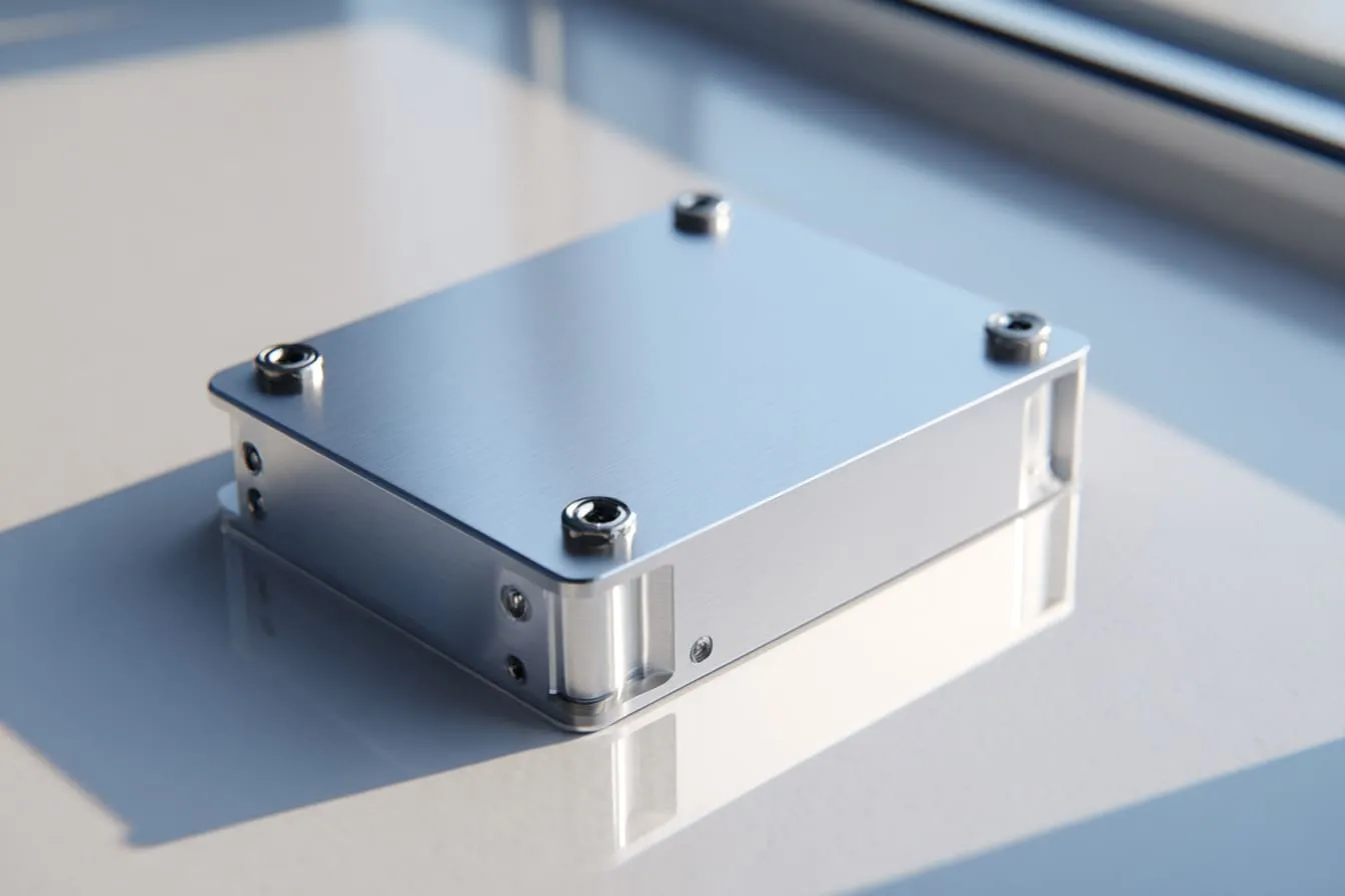
A visually perfect enclosure can still fail EMC because beauty and shielding are not the same thing. A clean surface does not prove good electrical contact. A tight-looking seam does not prove low resistance. A well-aligned panel does not prove continuous shielding.
I once discussed a project where the buyer was happy with the first sample photos. The anodized surface looked rich. The corners looked clean. The laser-cut openings were sharp. From a purchasing view, the enclosure felt ready.
Then the engineer asked one question: “Did we keep bare metal at the contact points?”
That one question changed the mood.
The product looked finished. But electrically, some contact areas were blocked by coating. So the enclosure was not acting as one connected metal body.
The eye said yes.
The test chamber said no.
My own judgment on these projects is simple: I do not trust a good-looking enclosure until I know where the current can pass, where the panels bond, and where the shield may break.
What does “visual quality” actually measure?
Visual quality mainly checks appearance and mechanical workmanship. It is important. I do not ignore it. A poor-looking enclosure can damage the buyer’s brand. A scratched surface can make a good product feel cheap. A crooked panel can make the whole assembly look careless.
But visual quality has limits.
It usually measures things like:
| Visual Check Item | What It Tells You | What It Does Not Tell You |
|---|---|---|
| Surface finish | Whether the coating looks even | Whether the surface conducts electricity |
| Color consistency | Whether parts match visually | Whether panels are electrically bonded |
| Screw alignment | Whether assembly looks neat | Whether contact pressure is enough |
| Seam appearance | Whether gaps look small | Whether high-frequency leakage is controlled |
| Machining accuracy | Whether parts match the drawing | Whether EMC paths were designed correctly |
This is why a buyer can approve the sample by photo but still face EMC failure later.
A camera can show scratches.
A camera cannot show contact resistance.
A visual checklist can catch dents.
It cannot catch a broken shielding path under a beautiful black coating.
What does EMC performance really depend on?
EMC performance depends on how the enclosure handles electromagnetic energy. The metal body should reduce unwanted interference. It should also stop internal noise from escaping and external noise from entering.
That sounds technical, but the idea is very practical.
A good EMC enclosure needs:
- Continuous conductive paths
- Low-resistance bonding between panels
- Controlled seams and openings
- Good grounding design
- Proper cable and connector shielding
- Correct material and finish choices
For example, aluminum itself can be a good shielding material. But if the panels are separated by anodizing, powder coating, paint, loose screws, or uneven pressure, the enclosure may not work as one shield anymore.
It becomes a set of nice-looking metal pieces.
That is not the same as a proper EMC enclosure.
Where the disconnect happens
The disconnect often happens because different teams look at the same enclosure in different ways.
| Team | What They Often Focus On | What They May Miss |
|---|---|---|
| Purchasing team | Price, finish, lead time, packaging | EMC design details |
| Mechanical engineer | Dimensions, assembly, structure | Contact resistance |
| Brand owner | Surface quality, logo, appearance | Conductive continuity |
| EMC engineer | Leakage paths, grounding, bonding | Cosmetic details |
| Factory production team | Machining, coating, assembly | Testing conditions |
This is where trouble starts.
If EMC is discussed only after the enclosure is already designed, the factory may have fewer easy options. The buyer may need to change finish areas, add gaskets, redesign seams, or adjust cutouts.
And none of these changes feel pleasant at the end of a project.
A nice enclosure can still fail because the review was too visual and too late.
I always feel a small pressure when a buyer sends only a 3D drawing and says, “Just make it beautiful.” Beautiful is good. But for EMC projects, beautiful is not enough.
How Does EMI Leakage Occur in Metal Enclosures?
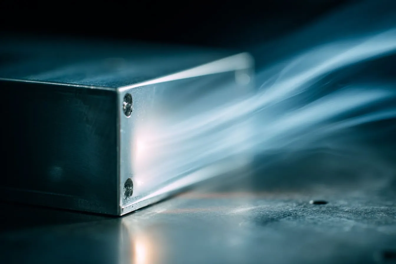
EMI leakage happens when electromagnetic energy finds a weak path through the enclosure. The weak path can be a seam, a slot, a cable opening, a vent, or even a poor contact point between two metal parts.
It is a bit like water leaking from a pipe. The pipe does not need to be broken in half. A small crack can be enough.
For EMI, the “crack” can be much smaller than what looks dangerous to the eye.
This is where many people underestimate the problem. They look at the enclosure and say, “The gap is tiny.” But high-frequency noise can treat that tiny gap like an open door.
When I review a design, I do not ask only whether the enclosure is closed. I ask where the energy will escape if it is looking for the easiest path out.
What is EMI leakage in simple terms?
EMI leakage means unwanted electromagnetic energy passes through the enclosure instead of being blocked or controlled.
A metal enclosure should work like a shield. But the shield only works well if it is continuous. Once there is a gap, slot, or poor connection, the shield becomes weaker.
Here is a simple way I explain it to buyers:
| Simple Object | EMC Meaning |
|---|---|
| Umbrella with holes | Metal enclosure with gaps |
| Water coming through fabric | EMI passing through seams |
| Loose zipper on a bag | Poor bonding between panels |
| Open window in a room | Connector or vent opening |
| Tape over a crack | EMI gasket or conductive sealing |
The enclosure may still look complete. But electrically, it may have many little “windows.”
And EMI loves windows.
Common leakage paths
In metal enclosures, leakage does not usually happen randomly. It usually happens at predictable weak points.
| Leakage Path | Why It Fails | Common Project Example |
|---|---|---|
| Panel seams | Poor electrical contact | Top cover touches base but coating blocks contact |
| Door edges | Long gaps around access doors | Control box door has no conductive gasket |
| Cable entry points | Shield is not terminated well | Cable shield stops before the connector |
| Connector cutouts | Open space around port | USB or HDMI port has poor metal contact |
| Ventilation holes | Large open area | Long slot vents for airflow |
| Screw areas | Pressure is not even | Screws are too far apart |
| Painted surfaces | Conductivity is blocked | Powder coat covers bonding points |
I have seen buyers care a lot about the outer surface, but they ignore the cable entry. That is risky. In many real products, the cable is not a small detail. It can become the main antenna.
A cable can bring noise in.
A cable can send noise out.
So the enclosure and the cable should be treated together.
Frequency impact on leakage
EMC problems change with frequency. This is one reason they can feel confusing.
At lower frequencies, a small gap may not cause a serious issue. At higher frequencies, the same gap can become a problem.
This is not magic. It is about wavelength and how electromagnetic energy behaves.
| Frequency Situation | Design Risk |
|---|---|
| Lower frequency noise | Grounding and bonding may be more important |
| Higher frequency noise | Small seams and slots become more dangerous |
| Long narrow openings | Can act like slot antennas |
| Many small openings | Can add up if spacing and shape are poor |
| Poor cable shield connection | Can radiate strongly at certain frequencies |
This is why I am careful with long slots. A long, thin opening may look harmless. It may even look clean and modern. But in EMC design, long slots can be more dangerous than many small round holes.
Good appearance can hide a bad antenna shape.
That sentence sounds dramatic, but it is true often enough that I do not ignore it.
A buyer once told me, “We need the vent to look sleek.” I understood him. The product had to sell. But I also asked him, “Do you need sleek, or do you need it to pass?”
That is the real trade-off.
And seams are usually where this trade-off becomes very real.
Why Are Seams the Weakest Point in EMC Design?

Seams are often the weakest point because they are where one metal part meets another. A solid metal wall is easy to understand. A joint between two parts is more complicated. It needs pressure, contact, clean surfaces, and sometimes extra conductive materials.
A seam can look closed but still behave like a broken shield.
This is why I treat seams like a serious design feature, not just a place where parts meet.
The risky detail here is not always the visible gap. Sometimes the risky detail is the invisible contact surface under the cover, under the coating, or under the screw head.
How seam design affects shielding
Different seam designs create different EMC behavior.
| Seam Type | Visual Result | EMC Risk | My Practical View |
|---|---|---|---|
| Simple butt joint | Clean and easy | Higher leakage risk | I avoid it for stricter EMC needs |
| Overlap joint | Slightly more material | Better shielding path | Good basic improvement |
| Tongue-and-groove | More complex | Stronger leakage control | Better for serious EMC projects |
| Labyrinth seam | More design work | Better high-frequency control | Useful when testing pressure is high |
| Gasketed seam | Needs extra material | Can improve contact | Good if compression is controlled |
A simple butt joint may look neat. But it gives EMI a direct line through the seam. An overlap joint makes the path more difficult. A tongue-and-groove or labyrinth structure can make the leakage path even harder.
This is like sound coming through a door.
A straight gap lets sound pass easily.
A twisted path reduces it.
EMI is not exactly sound, but the thinking is similar. Straight openings are usually more risky.
The role of contact resistance
Contact resistance is one of those terms that sounds boring until it ruins a project.
Two metal parts can touch each other, but the electrical contact may still be poor. The surface may have oxide. The coating may block contact. The pressure may be uneven. The surface may be too rough or too dirty.
In real work, I pay attention to the contact area before I praise the seam appearance, because a seam that looks tight but does not conduct well is only giving me a false sense of safety.
Common causes of poor contact include:
- Anodized surfaces touching each other
- Powder coating on mating areas
- Paint under screw heads
- Oxidation on aluminum surfaces
- Low screw pressure
- Uneven gasket compression
- Warped panels
- Surface contamination
Here is a practical comparison:
| Contact Condition | Visual Appearance | EMC Result |
|---|---|---|
| Bare metal with strong pressure | May look ordinary | Usually better conductivity |
| Coated surface with tight fit | Looks excellent | May block current |
| Loose screw with clean surface | Looks acceptable | Poor contact under vibration |
| Conductive gasket with wrong compression | Looks professional | May still fail |
| Masked bonding area | May need planning | Often more reliable |
This is why finish drawings matter. If the drawing only says “black anodized” or “powder coated,” the factory may coat everything. That can look beautiful. It can also block key contact points.
Fasteners and spacing issues
Screws do more than hold the enclosure together. In many designs, they also help create pressure between panels.
But screw design has limits.
If screws are too far apart, the panel may lift slightly between fasteners. The gap may be small. The eye may not notice it. But EMC testing may notice it.
| Screw Design Issue | Possible EMC Problem |
|---|---|
| Screws too far apart | Long seam sections can leak |
| Uneven torque | Contact pressure changes across seam |
| Coating under screw head | Screw does not bond well |
| Thin cover plate | Panel flex creates uneven contact |
| No gasket between screws | Gaps remain between contact points |
I have learned not to treat screw quantity as only a cost issue. Yes, more screws add assembly time. Yes, more holes add machining work. But fewer screws can create a hidden EMC cost later.
A cheap seam can become an expensive test failure.
That is the kind of cost that does not show up clearly in the first quotation.
And coatings can make this even more painful.
How Do Surface Finishes Destroy Conductivity?
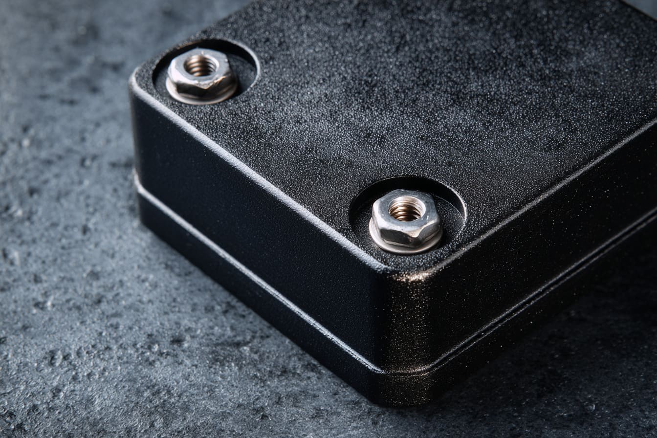
Surface finishes can destroy conductivity because many finishes are not conductive. Anodizing, powder coating, and painting can protect the enclosure and make it look better. But they can also block electrical contact between metal parts.
This is one of the most common traps in aluminum enclosure projects.
A buyer wants the enclosure to look premium. That is normal. A black anodized aluminum enclosure looks clean. A powder-coated sheet metal enclosure can look strong and brand-ready. A painted surface can match the final product design.
But EMC may need bare metal in certain places.
That is the tension.
For finish choices, I usually ask myself one uncomfortable question first: which surface must look beautiful, and which surface must stay electrically useful?
What happens with anodizing?
Anodizing is popular for aluminum enclosures. It improves surface hardness and corrosion resistance. It also gives a clean, premium look.
But anodizing creates an oxide layer on aluminum. That layer is not the same as bare aluminum. It can reduce surface conductivity at contact points.
So two anodized panels may touch physically but not bond well electrically.
| Anodizing Benefit | EMC Concern |
|---|---|
| Better corrosion resistance | Contact surfaces may become less conductive |
| Better wear resistance | Grounding points may need masking |
| Better appearance | Electrical bonding may be blocked |
| Good color options | Color areas may not be good contact areas |
This does not mean anodizing is bad.
I use anodizing often.
But I do not treat anodizing as only a cosmetic choice. For EMC-sensitive projects, the drawing should define masked areas, grounding areas, and contact zones.
A simple note can help:
- Keep inside bonding points uncoated
- Mask screw contact areas
- Use conductive hardware where needed
- Add grounding studs if required
- Confirm finish thickness and contact method
The problem is not anodizing itself.
The problem is blind anodizing.
Impact of powder coating and painting
Powder coating and painting create an even bigger issue in many sheet metal enclosures. These finishes are usually insulating. They are great for appearance and corrosion protection. But they can block grounding and bonding paths.
I have seen powder-coated enclosures that looked excellent but had poor electrical connection between the cover and base. The coating was too complete. It covered the places where metal needed to touch metal.
That is a funny problem.
The factory did the coating too well.
| Finish Area | Good for Appearance? | Good for Conductivity? | Common Fix |
|---|---|---|---|
| Outer surface | Yes | Not needed | Coat normally |
| Inner contact flange | Not always visible | Very important | Mask or remove coating |
| Screw hole area | Sometimes visible | Important | Mask around holes |
| Grounding stud area | Usually hidden | Very important | Keep bare metal |
| Door seam area | Partly visible | Important | Use gasket or masked strip |
Powder coating can also create tolerance issues. If the coating is thick, it can change fit. The panels may close tighter or differently than expected. That can affect gasket compression and contact pressure.
So the finish is not just a color layer.
It becomes part of the mechanical and electrical design.
When finishes are necessary
Some buyers ask, “Can we just avoid coating?”
Sometimes yes.
Sometimes no.
A product may need corrosion resistance. It may need a brand color. It may be used outdoors. It may be touched often. It may need to match another product line. In those cases, finishes are necessary.
The smarter question is not “finish or no finish.”
The smarter question is “where should the finish stop?”
| Project Need | Finish Strategy |
|---|---|
| Outdoor use | Use coating, but mask bonding points |
| Premium appearance | Finish visible surfaces, protect contact areas |
| EMC-sensitive product | Use conductive treatment or selective masking |
| High-volume production | Define masking clearly to reduce mistakes |
| Harsh environment | Balance corrosion and conductivity carefully |
Selective masking is often a good solution. It allows the enclosure to look good on the outside while keeping key electrical areas functional.
This is where supplier experience matters. If the supplier only cares about the color, they may miss the real purpose of the contact surfaces.
A pretty enclosure is nice.
A pretty enclosure that passes EMC is better.
Grounding is the next place where many people think they are safe, but they are not.
Why Is Grounding Often Misunderstood in Enclosure Design?
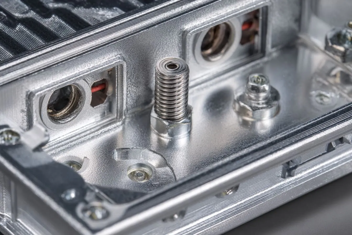
Grounding is often misunderstood because people use the word too loosely. Some people think grounding means “connect one wire somewhere.” Some people think the screw connection is enough. Some people think the metal enclosure automatically solves all noise problems.
It does not work that way.
Grounding and shielding are related, but they are not the same thing.
A shield without good bonding may leak.
A ground wire without a good enclosure design may not fix the problem.
The small detail I watch here is whether the grounding path is low-resistance in real assembly, not just whether the drawing shows a ground symbol.
Difference between grounding and shielding
Grounding gives current a reference path. Shielding blocks or reduces electromagnetic interference.
They often work together. But one cannot always replace the other.
| Term | Simple Meaning | Common Mistake |
|---|---|---|
| Grounding | Provides a reference or return path | Assuming any wire is enough |
| Bonding | Connects metal parts electrically | Assuming touching parts are bonded |
| Shielding | Blocks or reduces EMI | Assuming metal always shields well |
| Earthing | Safety connection to earth | Confusing safety with EMC performance |
For example, an aluminum enclosure can provide shielding. But if the cover and base are not bonded well, the shielding may be weak at the seam.
A ground wire may connect to the enclosure. But if the connection point is painted, loose, or high-resistance, it may not work well.
This is why I like to see clear grounding details in the design, not just a general note.
Common grounding mistakes
Grounding mistakes often look small on paper. They become big during testing.
Here are mistakes I see often:
| Grounding Mistake | Why It Happens | Possible Result |
|---|---|---|
| Ground point is coated | Finish drawing is too simple | Poor electrical connection |
| Screw is used as only ground path | Easy assembly assumption | Unstable contact |
| Ground wire is too long | Layout not planned early | Higher impedance |
| PCB ground and enclosure ground unclear | Electrical and mechanical teams not aligned | Noise problems |
| Only one bonding point used without review | Cost or habit | Weak high-frequency control |
| No serrated washer or contact feature | Hardware detail missed | Ground loosens over time |
I do not like vague grounding instructions. A note like “ground properly” is not a design. It is a wish.
A better drawing should show:
- Grounding stud position
- Bare metal area
- Hardware type
- Washer type
- Cable route
- Bonding points between panels
- Coating mask area
- Inspection method
This may sound like extra work. But it is much cheaper than guessing after a failed EMC test.
Internal vs external grounding paths
Many enclosure problems happen because the internal and external grounding paths are not considered together.
The PCB may have its own ground. The enclosure may have another path. The cable shield may connect somewhere else. The power input may add another condition.
If these paths are not planned, the product can behave differently during testing than expected.
| Area | Question I Ask |
|---|---|
| PCB mounting | Does the PCB ground connect to the enclosure? |
| Standoffs | Are they conductive or insulated? |
| Cable shield | Is the shield terminated to the enclosure? |
| Power input | Is the ground path safe and stable? |
| Door or cover | Is the moving panel bonded? |
| Coated surfaces | Are bonding points masked? |
I have seen designs where the PCB ground was correct in the electrical drawing, but the actual enclosure assembly blocked the connection. The engineer was not careless. The factory was not lazy. The problem was that the mechanical finish and electrical function were not discussed together.
That is a common real-world problem.
And once the enclosure has cutouts, vents, and connectors, the grounding discussion becomes even more serious.
How Do Cutouts and Openings Affect EMC Performance?
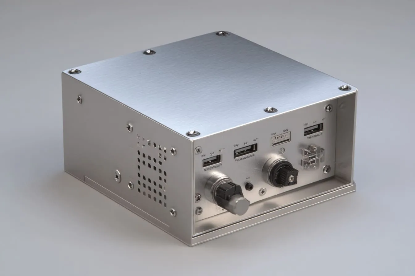
Cutouts and openings affect EMC because they break the metal shield. Every port, vent, cable hole, button opening, and connector space creates a possible leakage path.
No enclosure can be completely sealed in most real products. Devices need airflow. Users need ports. Cables need to enter. Buttons need access. Displays may need openings.
So the goal is not to remove every opening.
The goal is to design openings with control.
When I check cutouts, I do not only ask whether the connector fits; I ask whether the opening creates a path for noise that nobody will notice until the test.
Ports and connectors as leakage sources
Ports are easy to underestimate because they look normal. Every product has them. USB, HDMI, RJ45, DC power, antenna connectors, switches, displays, and cable glands all need space.
But EMC sees these openings differently.
| Opening Type | Common Risk | Better Thinking |
|---|---|---|
| USB cutout | Gap around connector | Ensure metal contact and shield connection |
| HDMI cutout | High-speed signal leakage | Control connector bonding |
| Power input | Conducted noise path | Plan filtering and grounding |
| RJ45 port | Cable can radiate | Use shielded connector if needed |
| Antenna opening | Intentional radiation area | Separate from sensitive circuits |
| Display window | Large non-metal area | Use shielded window if required |
A connector mounted in a metal wall does not automatically mean good shielding. The connector shield should bond well to the enclosure. The cutout size should not be too loose. The contact surface should not be blocked by coating.
A beautiful rectangular port with poor contact can still be a problem.
Ventilation design trade-offs
Ventilation is one of the hardest trade-offs in enclosure design.
Electronics produce heat. Heat needs airflow. Airflow needs openings. Openings reduce shielding.
That is the small fight inside many enclosure projects.
| Vent Design | Airflow | EMC Risk | Common Use |
|---|---|---|---|
| Long open slots | Good | Higher risk | Low EMC requirement products |
| Many small round holes | Medium | Lower than long slots | General electronics |
| Honeycomb vent | Good | Better shielding | EMC-sensitive enclosures |
| Shielded vent panel | Good | Better but higher cost | Industrial or telecom products |
| No vent | Poor | Better shielding | Low heat or sealed product |
I often see buyers choose long slots because they look clean and are easy to machine. I understand that. Long slots can make the enclosure look modern. But if EMC matters, long slots should be reviewed carefully.
Sometimes many small holes are safer.
Sometimes a honeycomb vent is better.
Sometimes the best answer is to move the heat source or change the airflow path.
Design is rarely one perfect answer. It is usually a trade-off with a price tag.
Cable penetration issues
Cables are another big EMC risk. A shielded enclosure can fail if the cable shield is not handled correctly.
A cable can become an antenna. It can carry noise out of the enclosure. It can also bring outside noise into the product.
| Cable Issue | What Can Go Wrong |
|---|---|
| Cable shield not bonded to enclosure | Noise may escape through cable |
| Plastic cable gland only | No conductive shield connection |
| Long unshielded wire inside enclosure | Internal noise can couple into cable |
| Connector floats from metal wall | Poor shield termination |
| No filtering at entry point | Conducted noise enters or leaves |
For some products, a simple plastic cable gland is fine. For EMC-critical products, it may not be enough.
This is where the buyer should be honest about the test target. If the product must pass strict EMC requirements, cable entry design should be part of the enclosure discussion from the beginning.
I have learned that the hole in the box is never just a hole.
It is a decision.
And many of these decisions are made too late.
Why Do EMC Problems Usually Appear Late in the Project?

EMC problems usually appear late because the project team often treats EMC testing as final confirmation instead of early design guidance. The enclosure gets designed, quoted, sampled, finished, assembled, branded, and shipped for testing. Then the EMC lab finds the weak points.
That timing is painful.
By then, every change feels expensive.
This is where project stress becomes very real. The buyer has a launch date. The engineer has pressure from the team. The factory has already made samples. The finish may already be approved. Everyone wants a small fix, but EMC problems do not always accept small fixes.
The project risk I care about most is not the failure itself; it is discovering the failure after the design has already become emotionally and financially “locked.”
Design-stage blind spots
At the design stage, many teams focus on the visible and mechanical parts first.
That is natural.
People ask:
- Does the board fit?
- Are the ports in the right place?
- Is the enclosure strong enough?
- Can the logo be printed?
- Can the color match the brand?
- Can the cost meet the target?
- Can the supplier make it fast?
These are good questions. But they are not enough for EMC.
The missing questions are often:
| Missing Design Question | Why It Matters |
|---|---|
| Where are the conductive contact points? | Needed for shielding continuity |
| Which areas should be masked before coating? | Prevents blocked bonding |
| Are seams designed for EMC? | Controls leakage |
| Are vents too large or too long? | Reduces radiation risk |
| How are cable shields terminated? | Controls cable-related EMI |
| Is grounding only assumed? | Prevents false confidence |
The blind spot is not always lack of knowledge. Sometimes it is schedule pressure. Sometimes it is a communication gap between electrical and mechanical teams. Sometimes the buyer assumes the supplier will “know what to do.”
But no supplier can guess every EMC requirement without clear discussion.
Sampling vs mass production differences
A prototype may pass, but production may fail. This sounds unfair, but it can happen.
Why?
Because small production differences can change EMC behavior.
| Difference | Prototype | Mass Production Risk |
|---|---|---|
| Screw torque | Hand-assembled carefully | Assembly pressure varies |
| Coating thickness | One sample checked closely | Batch variation appears |
| Masking accuracy | Sample handled by senior worker | Production workers may vary |
| Panel flatness | Best sample selected | Normal tolerance range appears |
| Gasket compression | Carefully adjusted | Can be uneven in volume |
| Hardware | Sample uses ideal parts | Substitution may happen if not controlled |
This is why a real EMC design should be production-friendly. It should not depend on one careful worker tightening one sample perfectly.
A good design should be stable enough for repeated assembly.
For buyers, this is important. A supplier can make one beautiful sample. But mass production needs process control.
That is where experience shows.
Testing stage surprises
EMC testing can feel like an exam where the questions are asked after the project is already finished.
The enclosure may fail radiation emission. It may fail immunity. It may show problems at certain frequencies. The lab may suggest adding tape, gaskets, ferrites, filters, or grounding changes.
Some fixes work.
Some fixes only hide the problem for one test condition.
| Late Fix | Possible Use | Limitation |
|---|---|---|
| Conductive tape | Quick seam test | Not ideal for production appearance |
| Extra gasket | Improves contact | Needs compression control |
| Ferrite on cable | Helps cable noise | May not solve enclosure leakage |
| Scrape coating | Improves bonding | Messy if not planned |
| Add grounding wire | Can help low-frequency issues | May not fix high-frequency seams |
| Change vent design | Strong solution | May require new tooling or machining |
Late fixes are not always bad. They can help diagnose the problem. But I do not like depending on emergency fixes as the main plan.
Emergency fixes cost time.
And for OEM buyers, time is often the most expensive part.
The better path is to design for EMC earlier, before the enclosure becomes difficult to change.
How Can You Design an Enclosure That Passes EMC from the Start?

You can design an enclosure for better EMC from the start by treating the enclosure as a functional shield, not just a protective box. That means the seams, finishes, grounding points, vents, cables, and fasteners should be planned before sampling.
This does not mean every project needs the most expensive EMC design.
That would be wasteful.
A small low-power device may not need complex gaskets or shielded vents. A high-speed industrial controller may need much more care.
Good design starts with the real risk level.
I usually decide how far to push EMC design by looking at the product’s signal speed, working environment, testing target, finish requirement, and cost limit together, not one by one.
Key design principles
The first principle is continuity. The enclosure should behave like one connected shield as much as possible.
That means metal parts should bond well at the right places.
Key principles include:
- Keep conductive paths continuous
- Reduce long straight gaps
- Control openings and slots
- Bond covers, doors, and removable panels
- Define grounding points clearly
- Avoid coating on contact zones
- Use EMI gaskets when needed
- Review cables and connectors early
| Design Principle | Practical Example |
|---|---|
| Continuous conductivity | Mask coating at panel contact areas |
| Shorter openings | Replace long slot with smaller holes |
| Better seam path | Use overlap instead of butt joint |
| Stable bonding | Add more fasteners or gasket |
| Clear grounding | Add bare-metal grounding stud |
| Cable control | Use shielded connector or conductive gland |
The goal is not to make the enclosure complicated.
The goal is to remove weak points before they become test failures.
Structural improvements
Structure matters a lot in EMC design. The shape of the seam, the screw spacing, and the panel stiffness all affect performance.
Here are practical structural improvements:
| Improvement | Why It Helps |
|---|---|
| Overlap seams | Reduces direct leakage path |
| Tongue-and-groove edges | Creates a more difficult path for EMI |
| Labyrinth joints | Improves high-frequency shielding |
| More fasteners | Improves contact pressure |
| Thicker cover plate | Reduces flex and uneven gaps |
| Conductive gasket channel | Holds gasket in correct position |
| Shorter vent slots | Reduces antenna-like openings |
A buyer may worry that these changes increase cost. That is true sometimes.
But the cost should be compared with the cost of failure.
A slightly better seam may cost more in machining.
A failed EMC test may cost weeks.
For custom OEM projects, weeks can hurt more than machining cost.
Material and finish strategies
Material and finish choices should match the EMC target.
Aluminum is common because it is light, easy to machine, and good for many enclosures. Sheet metal is strong and cost-effective for many industrial boxes. But material alone does not guarantee EMC success.
The finish must be handled correctly.
| Requirement | Possible Strategy |
|---|---|
| Premium appearance | Anodize visible surfaces, mask contact areas |
| Corrosion resistance | Use coating with defined bonding zones |
| Strong EMC bonding | Keep bare metal at seams or use conductive treatment |
| Outdoor use | Balance sealing, coating, and grounding |
| High-volume production | Make masking areas easy to inspect |
| Brand color | Avoid coating over grounding points |
For many projects, the best solution is not “no coating.”
It is controlled coating.
I like drawings that clearly show:
- Coated areas
- Uncoated areas
- Masked grounding points
- Gasket locations
- Screw contact zones
- Surface treatment notes
- Inspection requirements
A clear drawing saves many arguments later.
And after the design is improved, practical EMC solutions can still add another layer of safety.
What Are Practical Solutions to Improve EMC Performance?

Practical EMC solutions include EMI gaskets, conductive surface treatments, better grounding hardware, improved seam design, shielded vents, and pre-compliance testing. The right solution depends on where the enclosure is leaking and how much performance improvement is needed.
I do not like throwing random fixes at an EMC problem. That can waste money quickly.
A gasket cannot fix every grounding problem.
A ferrite cannot fix every seam problem.
A coating change cannot fix every cable problem.
The repair method should match the failure path.
When a project fails EMC, my first instinct is not to add parts immediately; I try to understand whether the failure is coming from seams, openings, grounding, cables, or finish choices.
Use of EMI gaskets
EMI gaskets help improve electrical contact across seams, doors, and covers. They are very useful when metal-to-metal contact is not enough.
Common gasket types include:
| Gasket Type | Good Point | Watch Out For |
|---|---|---|
| Conductive foam | Easy to compress | Can age or lose shape |
| Fabric-over-foam | Good for many enclosures | Needs correct compression |
| Metal finger stock | Strong conductivity | Can be harder to assemble |
| Conductive rubber | Good sealing plus conductivity | Higher cost |
| Wire mesh gasket | Durable in some cases | Surface may need planning |
A gasket must be compressed correctly. Too little pressure and it may not work. Too much pressure and it may deform or create assembly problems.
This is why gasket space matters in the enclosure design.
If the designer leaves no room for the gasket, the factory may add it later in a poor way. Then the product looks like it has an EMC solution, but the solution may not be reliable.
A gasket is not decoration.
It needs a place to live.
Conductive treatments
Conductive surface treatments can help when the enclosure needs both corrosion resistance and electrical bonding.
Some projects use chromate conversion coating. Some use conductive plating. Some use selective masking. Some use special conductive coatings.
The right choice depends on cost, appearance, corrosion needs, regulation needs, and EMC target.
| Treatment Strategy | Benefit | Limitation |
|---|---|---|
| Selective masking | Keeps key areas conductive | Needs process control |
| Chromate conversion coating | Good conductivity and protection | Appearance may not match premium finish |
| Conductive coating | Helps shielding inside plastic or metal areas | Needs thickness and adhesion control |
| Bare metal contact points | Simple and effective | Can oxidize if not protected |
| Conductive hardware | Improves bonding | Still needs clean contact surface |
I often prefer simple and controllable solutions. A small masked area around a grounding point can be more reliable than a fancy fix added too late.
The best EMC solution is usually the one production workers can repeat correctly.
That point matters more than many people think.
Testing and validation methods
Testing should not only happen at the end. Pre-compliance testing can help catch problems earlier.
A full certified lab test may be expensive and slow. But early checks can still reduce risk.
| Test or Check | Why It Helps |
|---|---|
| Continuity check | Finds poor bonding points |
| Contact resistance check | Shows weak electrical contact |
| Pre-compliance scan | Finds likely emission issues |
| Gasket compression review | Confirms assembly condition |
| Cable shield inspection | Finds weak cable termination |
| Prototype comparison | Checks if changes improve result |
For custom projects, I like step-by-step validation.
First, confirm mechanical fit.
Then confirm finish and contact areas.
Then confirm grounding.
Then test likely EMC weak points.
Then go into formal testing with fewer surprises.
This is not perfect. EMC can still surprise people. But it gives the project a better chance.
A buyer who chooses the right supplier also gets fewer surprises.
How Should Buyers Evaluate Suppliers for EMC-Critical Enclosures?

Buyers should evaluate suppliers for EMC-critical enclosures by checking whether the supplier understands electrical continuity, seam design, finish masking, grounding points, and production repeatability. A supplier who only talks about surface finish and machining tolerance may not be enough for EMC-sensitive projects.
This part matters to me because I am on the factory side. I know what buyers often ask. I also know what they sometimes forget to ask.
Many buyers ask, “Can you make this enclosure?”
For EMC projects, the better question is, “Can you help me avoid the failure points in this enclosure?”
That is a very different conversation.
My real test for supplier capability is whether the supplier asks uncomfortable design questions before quoting, because silence at the beginning often becomes extra cost at the end.
Questions to ask suppliers
A buyer does not need to become an EMC expert. But they should ask better questions.
Here are useful questions:
| Question | Why It Matters |
|---|---|
| Have you made EMC-sensitive enclosures before? | Shows real project experience |
| Which areas should remain uncoated? | Tests finish and bonding knowledge |
| Can you support masking on contact points? | Checks production control |
| How do you handle seam conductivity? | Shows understanding beyond appearance |
| Can you add EMI gasket space? | Checks design support ability |
| Can you review vent and cutout risks? | Helps avoid leakage paths |
| How do you inspect grounding points? | Shows quality control thinking |
| Can you keep production consistent after sample approval? | Tests mass production reliability |
A good supplier should not only say yes.
A good supplier should explain the risk.
Sometimes the best supplier answer is, “This design can be made, but this seam may be risky for EMC.”
That kind of answer may slow the discussion for one day.
But it can save weeks later.
Red flags in supplier capability
Some red flags are easy to spot.
If a supplier only talks about appearance, price, and delivery time, that is not always bad. For normal enclosures, those points matter. But for EMC-critical products, the conversation should go deeper.
| Red Flag | Why It Worries Me |
|---|---|
| Supplier says metal always blocks EMI | Too simple and risky |
| Supplier ignores coating at contact points | May create bonding failure |
| Supplier never asks about testing standard | May not understand project target |
| Supplier treats all seams the same | Weak EMC design thinking |
| Supplier cannot discuss grounding areas | High risk for assembly problems |
| Supplier focuses only on sample photos | Visual approval may hide electrical issues |
| Supplier cannot control masking | Mass production may vary |
Another red flag is overconfidence.
EMC is not something I like to promise blindly. A factory can support better enclosure design. It can control machining, coating, masking, gasket placement, and assembly. But the final EMC result also depends on the PCB, cables, connectors, power design, and test setup.
So I prefer honest suppliers.
Not dramatic suppliers.
Not magic suppliers.
Honest suppliers.
What a good supplier provides
A good enclosure supplier should provide more than a metal box.
For EMC-sensitive projects, the supplier should help review the design from a manufacturing and assembly angle.
| Supplier Support | Practical Value |
|---|---|
| Early design feedback | Reduces late changes |
| Finish masking suggestions | Protects bonding areas |
| Seam improvement options | Improves shielding path |
| Gasket placement advice | Helps contact consistency |
| Material suggestions | Balances cost, strength, and EMC |
| Prototype review | Finds risks before production |
| Production control | Keeps sample and batch consistent |
| Clear communication | Saves time across time zones |
For buyers like David, John, Jackson, and many OEM customers I work with, communication matters as much as machining. A buyer may have a smart design, but if the supplier does not confirm small details clearly, the project can still go wrong.
I have seen this many times.
A small missed note becomes a wrong finish.
A wrong finish becomes poor grounding.
Poor grounding becomes a failed test.
A failed test becomes delay.
And delay becomes cost.
That chain is why supplier evaluation should include technical thinking, not only price comparison.
Conclusion
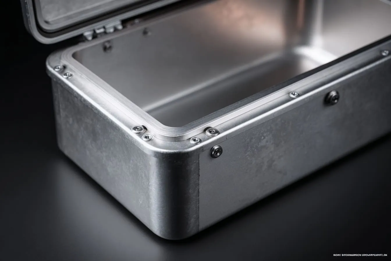
A metal enclosure can pass visual review but fail EMC because the real problem is often invisible. The surface may look perfect. The parts may fit well. The screws may sit cleanly. The logo may look sharp. But EMC performance depends on electrical continuity, bonding, grounding, seam design, openings, cable paths, and finish control.
I believe this because I have seen too many projects where people trusted appearance too much. I understand why it happens. Buyers want clean samples. Engineers want fast progress. Factories want to finish production smoothly. Everyone wants the project to move.
But EMC does not reward hope.
It rewards good contact.
It rewards clear drawings.
It rewards honest discussion before sampling.
It rewards boring details like masked grounding points, screw spacing, gasket compression, and cable shielding.
That is why I do not treat a custom aluminum enclosure as only a shell. I treat it as part of the product’s electrical behavior. If the product must pass EMC, the enclosure should be designed with EMC in mind from the first drawing, not after the failed report arrives.
For me, the best enclosure project is not the one that only looks beautiful in photos. It is the one that looks right, assembles well, protects the electronics, supports the brand, and gives the buyer fewer painful surprises later.
If you are working on a custom aluminum enclosure, sheet metal enclosure, Raspberry Pi-style project case, or OEM protective enclosure with EMC concerns, send your drawing, finish requirement, board layout, and testing target to us early.
At MaidaTech, we can help review the enclosure structure, seams, coating areas, grounding points, cutouts, and custom manufacturing details before production starts.
Because a good enclosure should not only pass the eye.
It should also pass the test.