Skip to content
A metal enclosure can look solid, neat, and expensive on the bench, yet still fail in a place many people barely notice.
That place is often the seam.
I have seen teams spend days looking at the PCB layout, cable routing, and grounding plan, only to find that the real EMI problem was sitting right between the lid and the base. That kind of mistake feels small at first. Then the test report comes back, the schedule slips, and everyone suddenly cares about a thin line of metal contact that seemed harmless before.
This is why I think enclosure seams deserve much more attention than they usually get.
EMI shielding sounds like a broad topic, and in one way it is. It touches material, assembly, layout, coating, fastening, and testing. But in aluminum enclosures, the seam often becomes the place where all those decisions collide. A nice-looking housing can still leak. A thick wall can still fail. A well-designed PCB can still suffer because the enclosure did not finish the job.
I do not judge an aluminum enclosure by how clean it looks after machining. I judge it by whether the current path stays continuous where two parts actually meet.
That is where real projects get uncomfortable.
Aluminum is useful. It is light. It machines well. It looks professional. It works for many OEM and ODM projects. I use it often, and for good reason. But it also comes with one quiet problem: the surface does not always stay electrically friendly, especially after anodizing, coating, or everyday oxidation. So the seam that should help contain noise can become the exact place where noise escapes.
And that escape is rarely free.
It can mean failed EMC tests, rework on samples, extra gasket cost, new machining steps, drawing changes, delayed shipment, and long email chains between the factory, the engineer, and the buyer. I have watched that happen more than once. No one enjoys paying twice for a mistake that started as a small assumption.
So in this guide, I want to stay practical.
I am not here to turn this into a textbook. I want to focus on what actually improves EMI shielding at aluminum enclosure seams: better contact, smarter surface treatment, better fastening, better gasketing, and better checking before production gets too far. That is the part that saves time, money, and headaches.
And once you see how much trouble a seam can create, the next question becomes very simple: what is EMI shielding really doing there in the first place?
What Is EMI Shielding and Why Do Seams Matter?
EMI shielding sounds technical, but the basic idea is not hard.
A metal enclosure helps contain unwanted electromagnetic energy. It also helps block outside interference from getting in. In simple terms, the enclosure acts like a barrier. People often describe that barrier as a Faraday cage. That phrase can sound a little grand, but the working idea is easy enough: if the conductive shell stays continuous, the enclosure can guide and reduce the energy that would otherwise leak or disturb nearby electronics.
How EMI shielding works in metal enclosures
A shielding enclosure works best when the conductive path stays unbroken around the protected space. That means the housing is not just a box in a mechanical sense. It is also an electrical path.
If that path is solid, the enclosure can do its job well. If that path gets interrupted, the shielding quality drops. This is why seams matter so much. The lid and the body may look like one product to the eye, but electrically they are separate metal parts that must behave like one continuous shell.
Here is a simple way I explain it to buyers:
| Part of the enclosure | Mechanical role | EMI role |
|---|---|---|
| Top cover | Closes the product | Must stay electrically connected to the base |
| Base | Holds the system | Forms the main conductive body |
| Seam | Joins the parts | Must not create an electrical weak point |
| Fasteners | Hold parts together | Help maintain contact pressure and continuity |
The problem is that many people judge the enclosure mostly by shape and strength. EMI does not care about appearance in the same way. EMI cares about continuity.
I tend to think of seams as electrical bridges disguised as mechanical joints, and that small mindset shift changes many design choices later.
Why seams are the weakest point
A seam is where one conductive path depends on another part, another surface, and another assembly step.
That is already risky.
Even a narrow gap can allow leakage, especially at higher frequencies. A seam does not need to look wide to perform badly. A tiny interruption, patchy contact, uneven pressure, or coated surface can weaken the whole shielding path. This is what makes seams so dangerous. They often fail quietly. The enclosure still looks finished. The product still powers on. The issue only becomes obvious when testing starts or field problems appear.
I have seen engineers feel confident because the enclosure used aluminum with good wall thickness, yet the seam still behaved badly because the mating area had poor contact. That is not rare. It is actually very common.
Common misconceptions engineers have
I think the biggest misunderstanding is this: metal does not equal shielding success by default.
That assumption causes trouble fast.
Another common mistake is trusting thickness too much. Yes, material thickness can matter in some cases. But seam continuity often matters more than adding more aluminum. A thicker lid with a poor seam is still a weak shield.
Here are a few ideas that often mislead teams:
- The enclosure is metal, so shielding must already be fine
- Tight screws automatically mean good electrical contact
- A premium anodized finish is always harmless
- Thicker walls can compensate for bad seam design
- A small seam gap is too small to matter
Most of these ideas sound reasonable until test time.
And that is the hard part. EMI often punishes assumptions that look harmless in CAD. Once you accept that, it becomes easier to ask the right question: what exactly causes leakage at aluminum seams?
What Causes EMI Leakage at Aluminum Enclosure Seams?
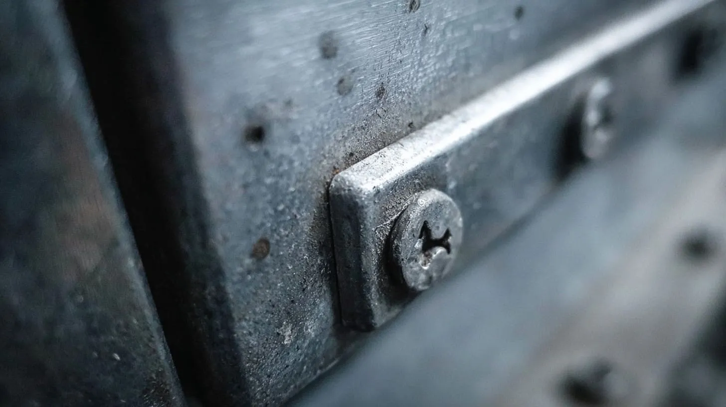
When EMI leakage shows up at a seam, the cause is usually not one dramatic failure. It is often a stack of small weaknesses.
That is why this topic can be frustrating.
A seam can look fine, assemble fine, and still behave poorly because several little details were never lined up properly. Surface oxidation, anodizing, weak pressure, loose fit, bad fastener choice, or poor bonding design may each look manageable alone. Put them together, and the seam starts acting like a door left half open.
The detail I pay close attention to is not whether the seam closes neatly, but whether the contact stays low-resistance and stable after coating, assembly, and real use.
Oxidation and surface resistance
Aluminum is useful, but it comes with a natural oxide layer. That oxide layer forms fast. It protects the metal in one way, but for EMI continuity, it is often a nuisance.
The trouble is simple. The surface may still look metallic, but electrically it is not the same as clean bare metal contact.
That means a seam can appear conductive to the eye while offering much more resistance than expected.
The oxide layer is thin. So people underestimate it. But thin does not mean harmless. At seam interfaces, especially under high-frequency conditions, that layer can weaken performance enough to matter.
This matters even more when:
- Contact pressure is low
- Surface area is small
- The seam opens and closes often
- Fasteners are spaced too far apart
- No conductive washer or gasket is used
| Condition | Risk at seam |
|---|---|
| Clean bare aluminum, strong compression | Lower risk |
| Oxidized contact area, low compression | Higher risk |
| Repeated opening and closing | Contact becomes less stable |
| Small point contacts only | Uneven electrical path |
Anodizing and coating problems
This is where many projects go wrong.
Anodizing looks good. It improves wear resistance. It helps corrosion resistance. It can make the product feel more premium. I understand why buyers like it. I like it too in many projects. But anodizing is not your friend when you need reliable metal-to-metal electrical contact at a seam.
That is because the anodized layer is insulating.
Paint and powder coating can create the same kind of problem. If the mating surfaces are fully coated, the seam may be mechanically closed but electrically interrupted. That is a very expensive kind of neatness.
Where coated seams usually fail
The most common trouble spots are:
- Lid flanges
- Base lips
- Screw contact zones
- Ground bonding points
- Inner panel overlaps
I have seen sample housings that looked excellent in photos and still failed because no one protected the critical contact zones from coating.
Mechanical gaps and poor fit
Good shielding needs contact. Contact needs fit. Fit needs control.
A seam can lose performance just because the parts do not mate evenly. Maybe the flange is not flat enough. Maybe the top cover warps slightly after machining. Maybe the tolerance stack pushes one edge outward. Maybe the screws pull down one side more than another.
Any of those can create uneven pressure and inconsistent contact.
What poor fit looks like in practice
Sometimes it is obvious. The seam visibly opens. Other times it is subtle. One corner compresses well, and another barely touches. That kind of inconsistency is hard to spot in a quick visual check.
I usually get nervous when I see a seam that depends on “close enough” machining instead of controlled contact geometry, because EMI problems love vague assembly conditions.
Poor fastening and bonding design
Fasteners are not just there to keep the box together. They affect contact pressure, contact consistency, and sometimes direct electrical continuity.
That is a lot of responsibility for a screw.
If the hardware spacing is poor, if the washers are wrong, if the torque varies too much, or if there is no clear bonding path, the seam can become weak fast. Some teams assume the screws will solve everything. But screws alone do not always break through oxide or coating consistently.
Weak fastening patterns that cause trouble
| Design choice | Likely result |
|---|---|
| Wide screw spacing | Poor pressure between screws |
| No conductive washers | Surface film may remain intact |
| Random torque on line | Contact varies unit to unit |
| No separate bonding path | Seam must do all the work alone |
And once these small causes stack together, the next question becomes obvious: how much does surface treatment change EMI performance?
How Surface Treatment Affects EMI Shielding Performance
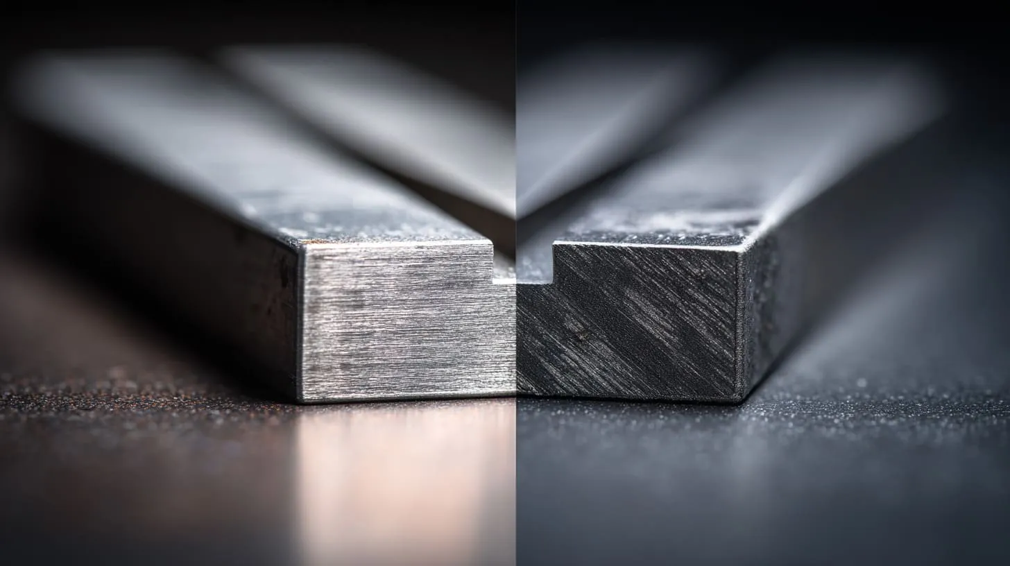
Surface treatment can help the product, hurt the shielding, or do both at the same time.
That is why I never treat surface finish as only a cosmetic decision.
In many projects, the finish gets discussed early for brand image and corrosion protection, but EMI is checked later. By then, the finish choice is already locked in, and people start trying to “fix” the seam with small patches. Sometimes that works. Sometimes it does not.
I get cautious the moment a finish looks perfect on paper but has no clear plan for how the seam will stay conductive after production.
Bare aluminum vs anodized aluminum
Bare aluminum usually gives you a better chance at direct electrical contact, especially at the seam. But bare aluminum is not perfect either. It can oxidize. It can mark more easily. It may not match the product image some buyers want.
Anodized aluminum solves some of those issues, but it creates another one: it reduces conductivity at the surface.
That trade-off matters.
A simple comparison
| Surface type | EMI seam contact | Corrosion resistance | Cosmetic finish | Risk level at seam |
|---|---|---|---|---|
| Bare aluminum | Better starting conductivity | Moderate | Basic | Medium |
| Clear anodized | Reduced conductivity | Better | Clean | High if seam is not masked |
| Black anodized | Reduced conductivity | Better | Premium | High if seam is not masked |
| Powder coated | Very poor direct contact | Good | Flexible | Very high at seam |
| Conductive coating | Can help if selected well | Varies | Moderate | Depends on material and process |
The right answer depends on the project. But what matters is that the seam cannot be treated as an afterthought once the finish is chosen.
Selective masking techniques
This is one of the most practical fixes.
If you need anodizing or coating on most of the enclosure, you can keep the critical mating zones uncoated. That way, you get the look and protection where you want them, while preserving conductivity where you need it.
This is often called masking. It sounds simple. In real production, it needs very clear instructions.
Where masking usually matters
- Lid-to-base contact flanges
- Screw seating areas
- Ground terminal zones
- Internal bonding points
- Gasket contact paths
I have learned that “leave seam conductive” is not enough as a note on a drawing. If the masking area is not clear in size and location, people will interpret it differently, and that is where expensive confusion begins.
Conductive coatings and plating options
Sometimes the project cannot rely on bare contact areas alone. In that case, conductive coatings or plating may help.
These options can improve seam performance, but they also add cost, process complexity, and supplier requirements. They are not magic.
Common options
| Option | Strength | Weak point |
|---|---|---|
| Conductive paint | Good for some applications | Wear and consistency can vary |
| Nickel plating | Good conductivity | Extra cost and process control needed |
| Tin plating | Useful in some contact areas | Not always ideal for full enclosure use |
| Chemical conversion coating | Better conductivity than heavy coating | Limited cosmetic appeal |
This is one of those places where the “best” option is rarely universal. A low-risk indoor unit may do well with masked bare contact areas. A high-frequency, higher-risk design may need a more controlled conductive treatment.
And once the surface is chosen, the physical seam geometry starts to matter even more.
How to Design Better Mating Surfaces for EMI Shielding
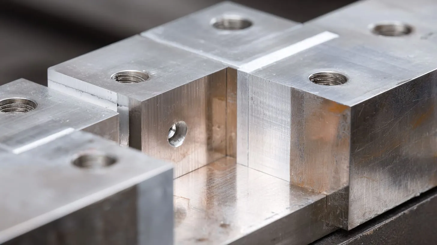
A weak seam often starts with weak geometry.
That sounds blunt, but I think it is true.
If two parts do not meet in a stable, repeatable, contact-friendly way, the best coating plan and the best hardware can only do so much. A mating surface is not just a place where two metal parts touch. It is the structure that decides how well they touch, where they touch, and whether they keep touching after assembly and use.
What often changes my mind during a design review is not the drawing complexity, but whether the seam gives me confidence that contact will stay broad and even on a real production line.
Increasing contact area
More contact area usually means a better chance for stable continuity.
This is why flange width, overlap design, and seam shape matter. A wide, well-controlled contact path is often more forgiving than a narrow edge that depends on tiny points of pressure.
Useful seam forms
- Flat overlap seams
- Step seams
- Tongue-and-groove designs
- Continuous flange contacts
| Seam design | EMI benefit | Production note |
|---|---|---|
| Narrow edge contact | Low | Sensitive to tolerance |
| Wide flat flange | Better | Easier to control |
| Tongue-and-groove | Better shielding path | More machining effort |
| Overlap seam with gasket | Strong in many cases | Adds parts and cost |
A bigger contact area also spreads the pressure better. That makes the seam less dependent on one perfect fastener or one exact spot.
Improving contact pressure
Contact area alone is not enough. Pressure matters too.
A large seam with weak pressure can still perform badly. What you want is even compression across the seam, not just hard clamping at a few screw points.
Why point-contact designs struggle
If the seam only presses tightly near screws, the area between screws may behave like a loose line. That can allow leakage. It can also create unit-to-unit variation, which is even worse for production.
I get suspicious when the middle of a long seam depends on hope instead of compression, because EMI does not care that the corners feel tight.
Ways to improve pressure consistency
- Reduce fastener spacing where needed
- Use seam features that guide compression
- Add conductive gaskets for gap-filling
- Avoid warped or overly thin mating flanges
- Control flatness more carefully
Designing for repeatable assembly
A good design should survive real assembly, not just perfect assembly.
That means alignment features matter. Fastener placement matters. Tolerance control matters. If the seam can shift during assembly, the contact result will shift too.
Repeatability matters more than people admit
I have seen some samples pass early checks because one skilled technician assembled them carefully. Later, production units varied because the design itself was too sensitive. That is why repeatability is part of EMI design, not just manufacturing convenience.
| Design feature | Why it helps |
|---|---|
| Alignment pins | Keeps seam location stable |
| Formed lips or steps | Improves part nesting |
| Controlled screw pattern | Improves pressure balance |
| Defined masking zones | Reduces process variation |
And once the seam geometry is doing its job, the hardware that pulls it together becomes the next critical layer.
What Are the Best Fastening and Bonding Methods?
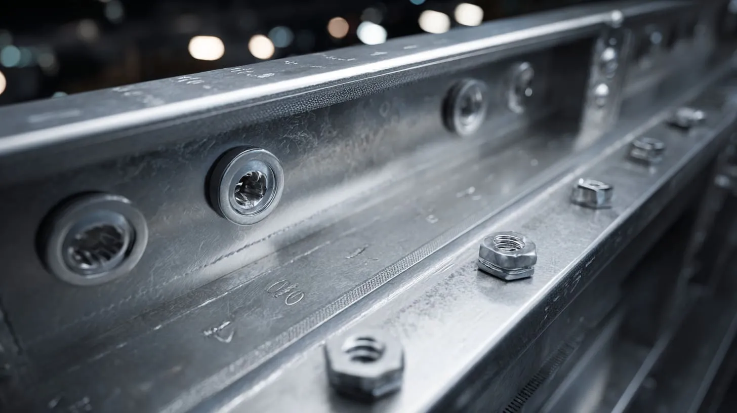
Fastening is one of those topics people think they understand until EMI problems show up.
A screw feels simple. A bolt feels familiar. Hardware looks like the easy part. But the truth is that fastening and bonding choices can quietly decide whether the seam acts like one shield or several disconnected pieces.
I often trust a modest seam with smart hardware more than a beautiful seam with lazy hardware choices.
Choosing the right fasteners
Fastener choice affects both mechanical hold and electrical behavior. That is why type, spacing, and placement all matter.
A few screws in the wrong places may hold the lid down, but still leave too much uncontrolled seam length between them.
What I look at first
- Distance between fasteners
- Pressure distribution along the seam
- Hardware stability over time
- Ease of repeatable tightening
- Whether the fastener also supports conductivity
| Fastener choice | Good point | Weak point |
|---|---|---|
| Standard screws | Easy and cheap | Contact may vary |
| Captive screws | Better assembly control | Still needs seam planning |
| Bolts with nuts | Strong clamping | Slower assembly |
| Dense screw spacing | Better seam compression | Higher assembly cost |
Using conductive hardware
This is where small parts can do big work.
Star washers and serrated washers are useful because they can bite into the surface and help break through oxide or light coating at the contact point. That improves the chance of reliable electrical contact.
But they are not a cure-all.
Where conductive hardware helps most
- Ground lug attachment
- Critical seam screw positions
- Bonding jumpers
- Small masked contact zones
A common mistake is using conductive hardware in one place and then assuming the entire seam is now solved. It is not. Hardware helps. Seam design still matters.
Adding grounding straps and bonding points
Sometimes the seam alone should not carry the full shielding job. In those cases, extra bonding paths are smart.
A copper braid, grounding strap, or dedicated bonding point can create a more controlled electrical connection between parts. This is especially useful when the seam opens often, when coatings complicate contact, or when the enclosure geometry is awkward.
When extra bonding is worth it
| Condition | Add bonding path? |
|---|---|
| Frequently opened cover | Often yes |
| High-risk EMI application | Often yes |
| Coated or anodized parts | Usually smart |
| Very simple low-risk seam | Maybe not needed |
I have become more willing to add dedicated bonding when a seam has too many chances to drift over time, because stability matters more than elegance in real use.
And when seams need extra help beyond hardware, gaskets usually enter the conversation.
How EMI Gaskets Improve Seam Shielding
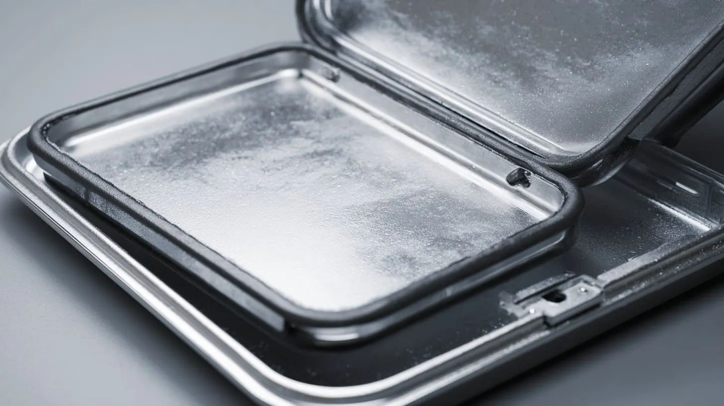
EMI gaskets exist because metal-to-metal contact is not always enough, not always stable, and not always easy to maintain.
A good gasket can fill gaps, improve seam continuity, and reduce leakage where rigid parts alone fall short. That can be a big help. It can also be misused. Some teams throw in a gasket late as a rescue move, almost like a bandage. Sometimes that works. Sometimes it just hides a weak seam design.
If I need a gasket to save a seam that never had decent geometry or pressure, I already know I am asking the gasket to do too much.
What are EMI gaskets and how they work
An EMI gasket is a conductive material placed at the seam to improve electrical contact and reduce leakage. It helps bridge small gaps and maintain continuity under compression.
That sounds simple, but the real value is in consistency. Gaskets can help absorb small variations in flatness, pressure, and fit that hard metal contact may not handle well.
Types of EMI gaskets
There are several common options, and each has its own use case.
Fabric-over-foam
This type is soft and easy to compress. It works well in many commercial products. It is useful when moderate compression and decent gap-filling are needed.
Conductive silicone
This option can work well where environmental sealing and electrical performance both matter. It is often more robust than lighter foam options, but cost can rise.
Beryllium copper finger stock
This is a more serious option for demanding applications. It offers strong conductivity and can perform very well, but it adds cost, design requirements, and handling considerations.
| Gasket type | Main strength | Main concern |
|---|---|---|
| Fabric-over-foam | Flexible and easy to fit | Can wear faster |
| Conductive silicone | Good balance of sealing and conductivity | Higher cost |
| Finger stock | Strong conductivity | Design and cost demands |
When to use gaskets vs metal-to-metal contact
Not every seam needs a gasket. That is important.
For some low-risk, well-designed seams with good bare contact and strong compression, direct metal-to-metal contact may be enough. But for higher frequencies, repeated opening, longer seam runs, or more variable assemblies, a gasket may be a smart move.
I usually stop resisting gasket cost when the seam must survive repeated service access, because repeated opening tends to turn “good enough” contact into future trouble.
And of course, even the best gasket will struggle if coating decisions get in its way.
How to Handle Coatings Without Killing Conductivity
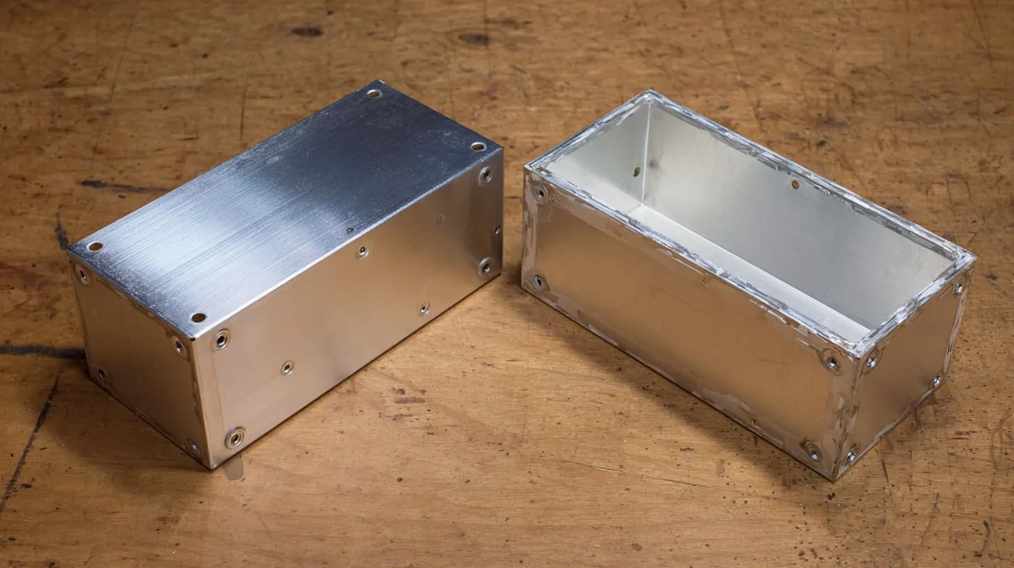
This is one of the most practical parts of the whole topic.
Many enclosure projects need coating. Buyers want corrosion resistance, good appearance, brand color, or surface durability. That is normal. I work on those requests all the time. The problem starts when coating spreads into places where conductivity is supposed to live.
Then the product looks better and shields worse.
This is where teams often need a more balanced view. A finish is not “bad” just because it hurts conductivity. It becomes bad only when no one plans around that trade-off.
I get far more confidence from a partly exposed, well-managed seam than from a fully beautiful finish that forces the electrical path to rely on guesswork.
Masking critical contact zones
Masking is one of the cleanest answers to this problem.
You keep the coating off the specific places that need electrical contact. That may include seam flanges, screw seats, grounding points, or gasket tracks. The rest of the enclosure can still receive the chosen finish.
Common masking mistakes
- Masking area too narrow
- Drawing note too vague
- Supplier and coater using different assumptions
- Contact zone shifting after redesign
- Missing mask at screw head or washer location
| Area | Should it be masked? | Why |
|---|---|---|
| Lid-to-base seam flange | Usually yes | Preserves seam conductivity |
| Decorative outer face | Usually no | No contact needed |
| Ground terminal spot | Yes | Stable bonding point |
| Internal bracket contact | Depends | Check electrical need |
Post-processing techniques
Sometimes the coating is already there, or the project changes late. Then post-processing may help.
This can include scraping, machining, or other removal methods to expose metal again at the contact points. It is not always elegant, but it can be practical.
Typical post-processing methods
- CNC cleanup on seam tracks
- Manual scraping on selected points
- Controlled sanding on bonding zones
- Chemical removal in defined areas
The weak side of post-processing is consistency. If it is not controlled well, one unit may perform better than another. So I prefer it as a deliberate process, not a rushed shop-floor fix.
Balancing corrosion resistance and EMI performance
This is the real design tension.
You want the enclosure to resist wear and corrosion. You also want reliable conductivity. In many cases, the smartest answer is not choosing one side completely. It is choosing where each side matters more.
Practical balance options
| Approach | Benefit | Trade-off |
|---|---|---|
| Full anodizing | Better appearance and protection | Poor seam conductivity |
| Full bare seam path | Better conductivity | Less surface protection |
| Partial masking | Good balance | Needs tighter process control |
| Conductive finish in selected zones | Controlled EMI support | Added cost |
When that balance is set well, testing becomes much more honest, because you are checking a seam that was designed to work, not just to look finished.
How to Test EMI Performance at Seams
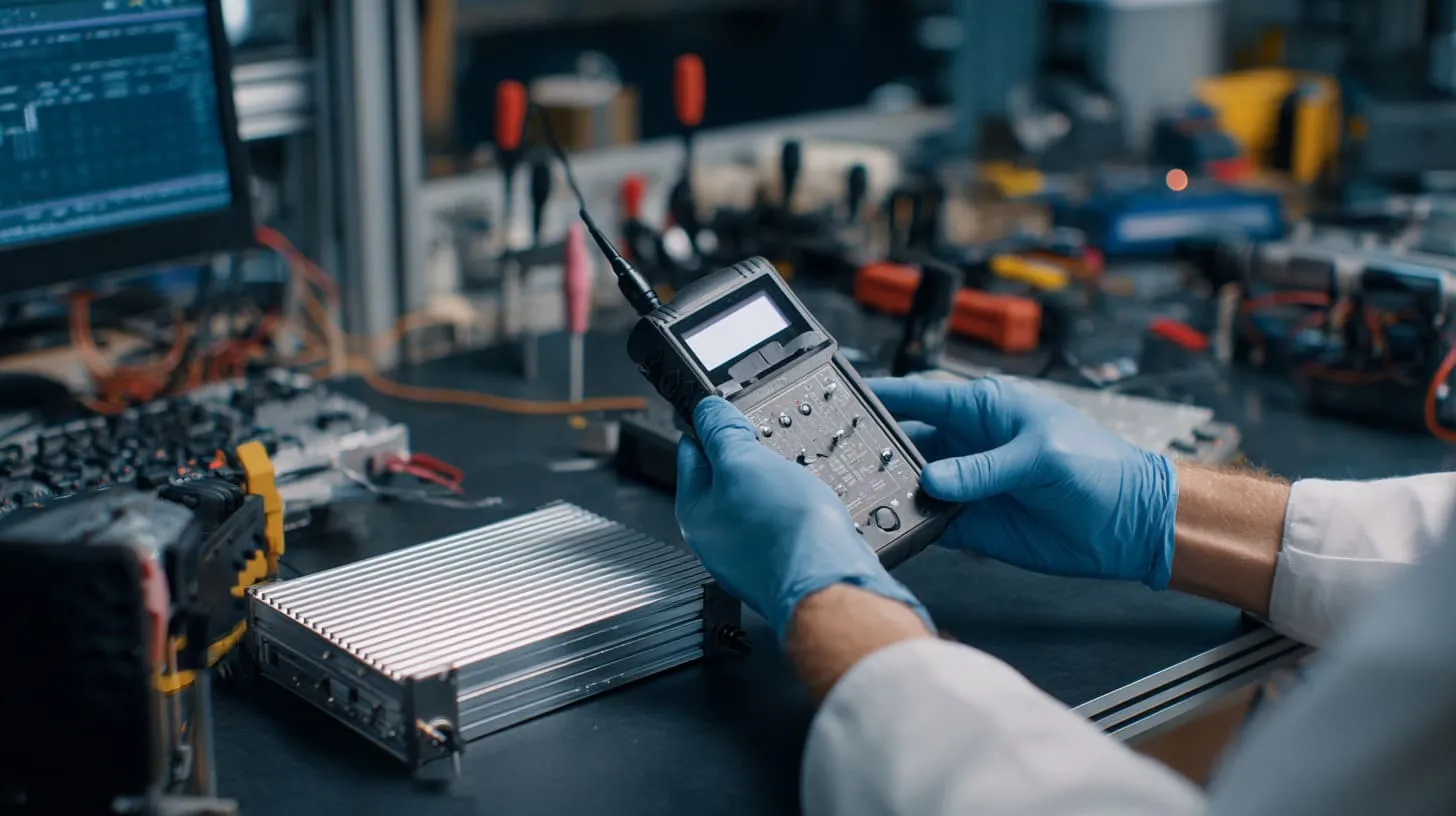
Testing saves pride from turning into delay.
I say that because many EMI seam problems come from assumptions that sounded reasonable in meetings. Testing pulls the conversation back to reality. And reality can be blunt. A seam either behaves well enough, or it does not.
The worst time to “discover” seam weakness is after cosmetic finish, final drawings, and customer timing are already locked.
I feel much safer when I see a team checking seam behavior early with simple tools instead of waiting for the lab to deliver the bad news all at once.
Pre-compliance testing methods
You do not always need a full lab test to learn something useful early.
Basic continuity checks across seam points can already show whether the contact is stable. Milliohm measurements are simple but helpful. Near-field probing can also reveal leakage patterns before formal testing.
Simple checks that help
- Resistance checks across multiple seam positions
- Comparison between corners and mid-seam points
- Open-close-repeat checks on service panels
- Hand inspection of masked or exposed contact zones
| Early test | What it tells you |
|---|---|
| Milliohm check | Basic continuity quality |
| Near-field probe | Leakage hot spots |
| Repeated assembly check | Contact stability over time |
| Visual seam inspection | Coating and fit issues |
EMC lab testing insights
Formal lab testing often shows where the seam is not doing its job, especially when emissions show strong leakage near edges, joints, or service covers.
The lab may not say, “your seam is the villain,” in those exact words. But the pattern often points there.
- Leakage near removable covers
- Better result after temporary seam pressure changes
- Stronger emissions around poorly compressed edges
- Different results between similar units
I have seen teams blame the board for days when a temporary copper tape bridge across the seam changed the result right away. That kind of moment teaches a lesson very fast.
Design validation before mass production
This is where discipline pays off.
A seam that only works on one golden sample is not good enough. The design needs to survive real machining, real coating, real assembly, and repeated production.
What validation should include
- Multiple assembled samples
- Surface treatment in real production condition
- Full hardware stack, not temporary substitutes
- Repeated open-close cycles if the design is serviceable
- Documentation of seam treatment for future batches
What changes my decision at this stage is not the best test result, but the worst repeatable result, because production lives closer to that truth than the perfect sample does.
And once testing shows where the seam goes weak, the recurring design mistakes become much easier to recognize.
Common Design Mistakes That Reduce EMI Shielding
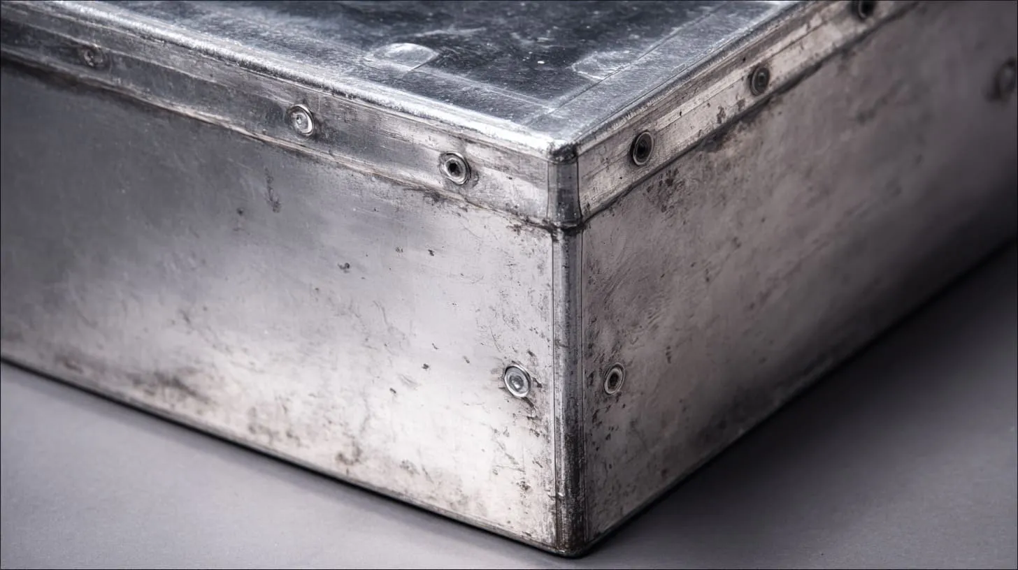
Most seam failures do not come from one shocking design error. They come from ordinary mistakes that people accept too easily.
That is what makes them dangerous.
A team may be smart, experienced, and careful, yet still miss the seam because everyone is focused on bigger-looking things. PCB layout feels bigger. Material grade feels bigger. Thermal design feels bigger. The seam looks like a detail. EMI has a nasty habit of proving otherwise.
The mistake I see most often is not lack of knowledge, but putting confidence in the wrong detail too early.
Over-reliance on enclosure thickness
This is a classic one.
A thicker aluminum wall may help the enclosure feel more solid. It may help mechanical strength. It may even help in some shielding contexts. But it does not fix a seam that lacks continuity.
A thick box with a weak seam can still leak like a thinner one.
Why this belief stays popular
Thickness is easy to understand. It feels tangible. Buyers like visible strength. Engineers can point to it in drawings. Seam quality is less dramatic, so people postpone it.
Ignoring surface treatment impact
Another mistake is choosing the finish first and thinking about conductivity later.
That order creates trouble, especially with anodized or coated enclosures. Once the visual and corrosion requirements are set, the seam may already be compromised unless masking or conductive treatment was planned in time.
Poor communication with suppliers
This matters more than many people admit.
A drawing may show the shape clearly but say almost nothing about the electrical function of the seam. Then the supplier treats it like a cosmetic or mechanical joint only. The part comes back looking right and performing wrong.
Missing instructions that often matter
- Exact masking area
- Contact resistance expectation
- Approved coating on seam zones
- Hardware type and washer detail
- Torque requirement
- Need for conductive gasket
| Missing detail | Result |
|---|---|
| No masking note | Coated contact path |
| No EMI note on seam | Supplier treats seam as cosmetic only |
| No hardware spec | Assembly varies |
| No torque control | Contact inconsistency |
Inconsistent assembly practices
A good design can still suffer from poor assembly control.
If the torque varies, if washers are missing, if the gasket is misaligned, or if one operator tightens in a different sequence, seam performance can drift. That drift is hard to see from the outside.
I do not relax just because the seam passed in engineering build, since assembly variation is where many “fixed” EMI issues quietly come back.
By this point, the natural question is not only what goes wrong, but where the money should actually go to prevent it.
Cost vs Performance: How to Optimize EMI Shielding Design

EMI design gets expensive very fast when the wrong fix comes late.
That is why I care a lot about where the budget goes. Not every project needs the most advanced gasket, the most complex plating, or the heaviest enclosure. But almost every project benefits from making the seam electrically honest from the start.
A lot of cost waste happens because teams spend late money on a problem that early design could have reduced much more cheaply.
The cost decision I trust most is the one that improves contact stability first, because stable basics usually beat fancy rescue methods later.
Where to invest for maximum impact
In many projects, the best return comes from:
- Better mating surface geometry
- Clear masking design
- Smarter hardware selection
- Controlled screw spacing
- Early seam testing
These are often more effective than just upgrading the material or adding bulk.
| Investment area | Typical value |
|---|---|
| Better seam design | Very high |
| Clear masking process | High |
| Conductive washers/hardware | High |
| Premium finish without seam plan | Low for EMI |
| Thicker wall only | Limited |
When EMI gaskets are worth the cost
Gaskets are worth it when the seam is high-risk, the frequency range is demanding, the cover opens often, or the geometry cannot guarantee enough stable contact on its own.
They are less attractive when teams use them only because the basic seam was never designed properly.
Avoiding over-engineering
This is important too.
Some teams react to EMI risk by adding too much: thicker parts, more screws, extra plating, more gasket cost, tighter machining, and more assembly time. That can solve the problem, but it can also damage the budget and the production flow.
A more balanced view
| Choice | Benefit | Risk |
|---|---|---|
| Simple seam + good masking | Cost-effective | Needs discipline |
| Seam + gasket + good hardware | Strong performance | Higher part cost |
| Heavy redesign after failure | Can solve issue | Slow and expensive |
| Overbuilt from day one | Lower EMI risk | Higher ongoing cost |
A reasonable design is not the cheapest design and not the heaviest one either. It is the one that matches the real EMI risk without forcing the project to carry unnecessary cost forever.
And once those trade-offs are clear, it helps to end with something practical enough to use on real projects.
Practical Design Checklist for Engineers and Buyers
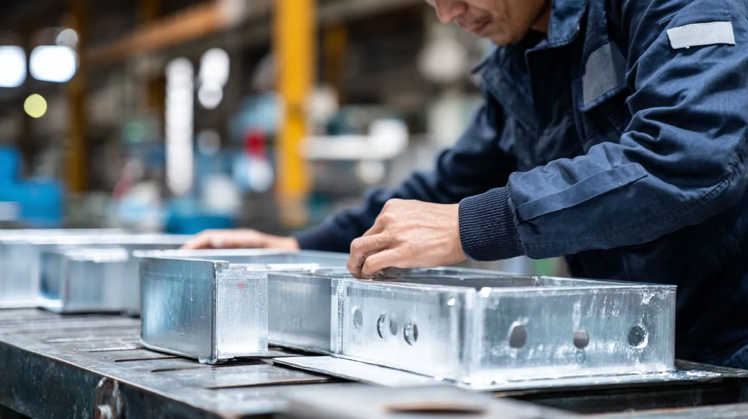
A checklist will not replace judgment, but it can stop easy mistakes from slipping through.
I like checklists most when they are short, practical, and tied to real failure points. This topic has enough small traps that a buyer, engineer, or factory team can all benefit from one shared view before samples move too far.
I trust a project more when the seam requirements are written clearly enough that the coating shop, assembly line, and buyer would all interpret them the same way.
Key questions before finalizing enclosure design
Before final release, I would check these points:
- Are the seam contact areas actually conductive?
- Is the seam wide enough for stable contact?
- Is contact pressure even across the full seam?
- Will repeated opening damage the contact path?
- Are fasteners spaced well enough?
- Does the design depend too much on one small contact point?
Supplier communication checklist
This part is often overlooked, so I want to be direct here.
If the factory does not know the seam is electrically important, the factory may optimize it for appearance or speed only.
What should be clearly documented
| Item | Why it matters |
|---|---|
| Masking area drawing | Prevents coating mistakes |
| Surface finish note | Defines where conductivity must remain |
| Fastener type | Supports repeatable contact |
| Washer type | Helps break through oxide or coating |
| Torque requirement | Controls compression consistency |
| Gasket spec | Prevents substitution confusion |
A short list for supplier discussion:
- Show exact seam contact zones
- Confirm coating exclusion areas
- Confirm bonding point locations
- Confirm assembly sequence if critical
- Confirm gasket material and placement
- Confirm electrical check method
Quick inspection points before shipment
Even late in the process, a simple check can still catch trouble.
Useful pre-shipment checks
- Visual review of masked seam zones
- Hardware count and type check
- Random continuity check across seam positions
- Gasket placement check
- Assembly pressure consistency review
| Inspection point | What to look for |
|---|---|
| Seam edge | Coating where metal should be exposed |
| Screw positions | Missing or wrong hardware |
| Bonding points | Clean, exposed, stable contact |
| Gasket line | Gaps, twist, or compression issues |
| Sample continuity | Large variation from point to point |
That checklist may look simple, but small discipline there can save much larger pain later.
Conclusion
EMI shielding in aluminum enclosure seams is not only about using metal. It is about maintaining continuity where the enclosure naturally wants to break into separate parts.
That is why seams matter so much.
A seam can look clean and still perform badly. A thick housing can still leak. A premium anodized finish can still weaken shielding if the contact path is not protected. In real work, shielding success usually comes from a chain of practical decisions: better mating surfaces, enough contact area, even pressure, correct masking, useful hardware, smart gasket use, and early testing.
I have learned to treat the seam as an electrical feature first and a mechanical joint second, because that order catches problems earlier and prevents false confidence.
If you are designing or sourcing a custom aluminum enclosure and EMI matters to your project, do not wait until the lab tells you the seam was weak. Check it early. Define it clearly. Build it like it matters.
And if you want a second set of eyes on your enclosure design, seam treatment, or custom OEM housing plan, you can reach out to me at info@maidatech.com or visit maidatechenclosure.com. I am always happy to look at a real project and help turn a risky seam into a stronger one.