Skip to content
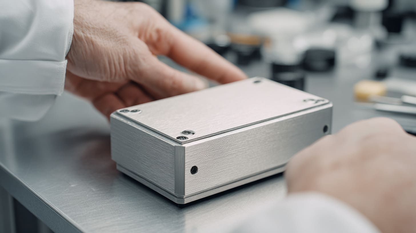
Metal-to-metal contact sounds comforting.
I understand why. Two metal parts touch each other. The enclosure closes. The screws go in. The seam looks neat. A lot of people see that and feel safe about EMC. To be honest, many teams do not even question it. The logic feels clean. Metal touches metal, so shielding must be fine. End of story.
But real work is rarely that kind.
I have seen enclosures that looked excellent on the table and still behaved badly in testing. The machining looked sharp. The finish looked premium. The lid sat flat. The assembly team felt confident. Then the EMC result came back, and the weak point was not the board, not the cable, not the filter. It was the contact path people trusted too easily.
That is why I do not treat metal-to-metal contact as proof of EMC safety. I treat it as a starting point that still needs to be questioned.
My own view comes from seeing how many failures hide inside small details. A seam can look tight and still leak. A fastener can feel secure and still fail to create a stable conductive path. A surface can look beautifully finished and still work like an insulator where it matters most. That gap between appearance and electrical reality causes a lot of pain.
I learned this lesson in a very ordinary way. A customer sent us a custom aluminum enclosure project for an industrial device. The housing looked simple. Everyone focused on the board mounting, port cutouts, logo finish, and lead time. Nothing looked unusual. But once the project moved closer to testing, the question changed. The real issue was not whether the lid closed well. The real issue was whether current could move across the joint in a stable way under real conditions. That small shift in thinking changed how I judge enclosure design.
The hard part is that bad contact often stays invisible. It does not announce itself. It hides under coating, light oxidation, weak pressure, or a seam that is mechanically acceptable but electrically weak. That is why I think this topic deserves more respect than it gets.
I do not judge a metal joint by how satisfying it looks after assembly. I judge it by whether it stays electrically useful after coating, fastening, vibration, handling, and time.
A lot of EMC trouble starts where confidence gets ahead of evidence. That takes us to a more basic question, and it is the one many people skip too fast.
What Does “Metal-to-Metal Contact” Actually Mean in EMC?

When people say metal-to-metal contact, they often mean something very simple. They mean two metal parts are physically touching. That is the visual definition. It is easy to understand. It is also incomplete.
In EMC work, the real question is not just Are these parts touching? The real question is Can current pass across this interface with low and stable resistance? Those are not the same thing.
That difference sounds small. It is not small at all.
Physical Contact vs Electrical Continuity
Physical contact is what the eye sees. Electrical continuity is what the current experiences.
A cover can sit against a base and still make poor electrical contact across most of the seam. The problem is that metal surfaces are not truly smooth. Under magnification, they look rough, uneven, and broken by tiny peaks and valleys. So even when two parts seem fully mated, real contact may happen only at limited points.
Then there is oxidation. Then oil from handling. Then machining residue. Then coating overspray. Each one reduces the quality of the path.
Here is a simple way I think about it:
| What I see in assembly | What may actually happen electrically |
|---|---|
| Lid sits flat | Only a few spots carry current |
| Screw is tight | Pressure may still be uneven across seam |
| Bare metal edge is present | Oxide layer may still raise resistance |
| Joint looks precise | Microscopic gaps may interrupt the path |
This is one reason why visual confidence causes problems. A neat-looking seam is not the same as a conductive seam.
I have seen teams say, “The lid is aluminum and the base is aluminum, so we are fine.” That sentence sounds reasonable, but it skips the part that matters most. Aluminum on paper is conductive. Aluminum in the real world often carries oxide, finish, contamination, or poor pressure distribution.
Contact Resistance and Its Impact
Contact resistance sounds technical, but the idea is simple. It is the resistance created where two parts meet. Even when both parts are conductive, the interface between them can still behave poorly.
That matters because shielding is not magic. Shielding works by giving unwanted currents a controlled path. When contact resistance gets too high, that path becomes weak. At low frequency, the issue may look small. At high frequency, it can become painful very fast.
I usually explain it like this: a metal enclosure is only as strong as the weakest electrical joint in the shielding path. One bad seam can reduce the value of a lot of good material.
A small table makes this easier to see:
| Condition at interface | Likely EMC effect |
|---|---|
| Clean bare contact with stable pressure | Better current flow |
| Oxidized or coated surface | Higher resistance |
| Limited point contact only | Unstable shielding path |
| Inconsistent assembly pressure | Repeatability problems |
What makes this tricky is that a product may still show continuity on a simple meter check. People see that and relax. But continuity alone does not tell the full story. A joint can pass a simple continuity check and still be poor for EMC because the impedance is too high for high-frequency current.
That is the kind of detail that gets ignored until testing day.
EMC Reality: Current Flow Across Interfaces
The enclosure is not just a box. In EMC terms, it is part of the current path.
That changes how I look at seams, screws, and mating surfaces. I do not see them as only mechanical features. I see them as electrical interfaces. If current cannot move smoothly across those interfaces, the shield becomes discontinuous. Once that happens, the seam can start behaving more like a leakage path than a barrier.
This is where things become very different from casual assumptions.
A seam with poor electrical continuity can act like a slot. A slot can radiate. A small interruption can let energy escape. The joint still looks like a joint. The enclosure still looks closed. But electrically, the path is broken enough to matter.
I think that is one of the biggest mental shifts engineers and buyers need to make. A protective enclosure is not only about shape and strength. It is also about invisible current behavior along the surfaces and across the joints.
Here is the contrast that matters:
- Mechanical thinking: the parts touch, so the job is done
- EMC thinking: the current path must stay continuous and low-impedance under real conditions
That one change in perspective saves a lot of mistakes.
Once that point becomes clear, the next question follows naturally: if metal-to-metal contact sounds so reasonable, why does it fail so often in actual work?
Why Metal-to-Metal Contact Often Fails in Practice
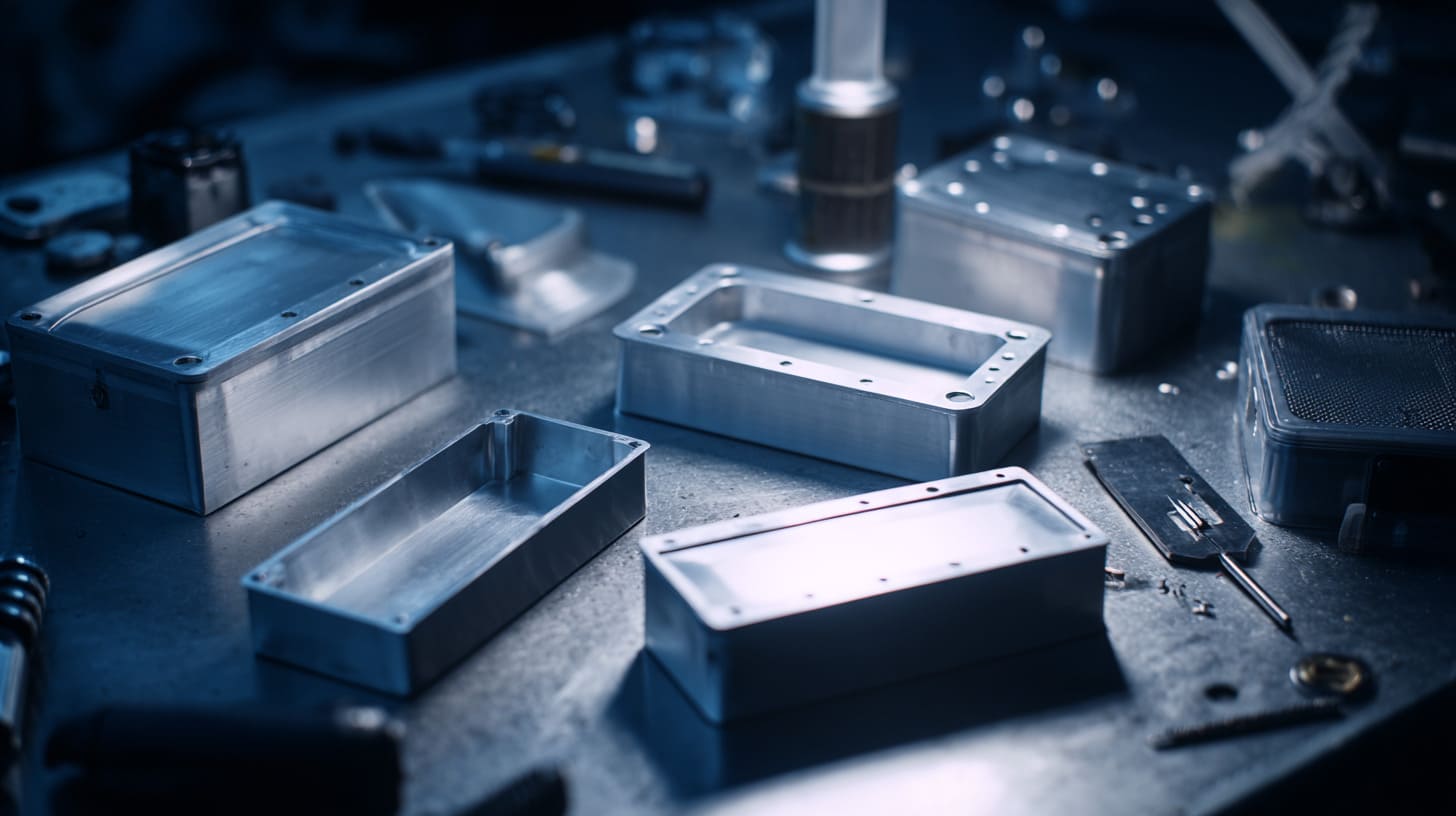
This is the part that frustrates people. The concept sounds right. The parts are metal. The lid closes. The screws are there. Still, the result can be bad.
I do not think most failures happen because engineers are careless. I think many failures happen because real production adds layers of mess that simple theory does not include.
The design says metal touches metal. Production adds finish, oxide, tolerance, torque variation, handling, and stress. That is where confidence starts to crack.
The first thing I pay attention to is not the drawing itself but all the tiny real-world conditions that sit on top of the drawing, because that is where a good-looking design quietly becomes a weak EMC joint.
Surface Finishes Break Conductivity
A beautiful finish can be the reason a joint stops working electrically.
This happens a lot with anodizing, powder coating, painting, and some plated surfaces. These finishes are useful. I am not against them. They improve corrosion resistance, appearance, brand value, and surface durability. In many products, they are necessary. But if people treat them as only cosmetic, they miss the EMC problem.
Anodizing on aluminum is a classic example. It looks clean. Customers like it. It protects the part. But anodizing also creates an insulating oxide layer. So if two anodized surfaces meet, the electrical path may be weak or almost gone unless conductive contact areas are deliberately managed.
I have watched teams spend hours discussing color, edge quality, and logo appearance, then give almost no attention to whether the critical joint surfaces should be masked or reworked for conductivity. That is how good-looking parts become electrically useless where they matter most.
| Surface condition | Mechanical value | EMC risk |
|---|---|---|
| Bare aluminum | Good conductivity | Oxidation risk |
| Anodized aluminum | Strong appearance and corrosion resistance | Poor direct conductivity |
| Powder-coated surface | Durable and attractive | Usually insulating |
| Selectively masked contact zone | Keeps appearance and function balanced | Better EMC performance |
The problem is not the finish itself. The problem is using finish without deciding where electrical contact still needs to survive.
Oxidation and Contamination
Even bare metal is not a simple hero.
Aluminum forms oxide very quickly. That oxide layer is thin, but it still matters. Then add fingerprints, assembly oil, cutting residue, dust, and storage contamination. Now the surface that looked conductive on the drawing has become less reliable in real life.
This issue is easy to underestimate because contamination feels minor. It does not look dramatic. It is not a cracked part. It is not a missing screw. It is just a bit of surface reality. But EMC problems often grow from these “small” things.
I have seen enclosures assembled after multiple handling steps, sample reviews, logo checks, and packaging movement. Every step adds more opportunities for contamination. If the contact path depends on clean direct metal contact, then the process has to support that requirement. Many factories do not fully think that part through.
A simple checklist helps here:
- Was the contact area protected during finishing?
- Was the mating area cleaned before assembly?
- Was the part stored in a way that avoided added contamination?
- Did the assembly process preserve the contact zone?
- Did anyone confirm the condition after rework or inspection?
A lot of failed assumptions live inside those questions.
Uneven Pressure and Contact Instability
Even good surfaces can fail if the pressure is poor.
This is one of the most overlooked problems I see. The metal parts may be conductive. The seam may be designed well enough. But if the contact pressure is uneven, the real electrical path becomes unstable. That instability can come from warping, poor flatness, weak screw layout, uneven torque, or simple tolerance stack-up.
A seam is not automatically good because screws exist. Screw location matters. Screw count matters. Torque matters. The flatness of the parts matters. If one area gets strong pressure and another area floats slightly, current does not care that the lid is “basically closed.” It will respond to the actual path, not the intended one.
I have worked on projects where one corner looked fine by eye but behaved differently after assembly because the pressure pattern across the lid was uneven. That is the sort of issue that can produce annoying repeatability problems. One unit passes. Another struggles. A third acts differently after shipping.
| Pressure condition | Likely outcome |
|---|---|
| Uniform pressure across seam | More stable contact path |
| Tight screws at wide spacing | Local contact, weak areas between screws |
| Uneven torque | Variable interface quality |
| Warped cover or base | Floating zones and leakage risk |
This is one reason I do not trust “assembled” as a quality judgment. I want to know how it assembled and where the pressure really sits.
Small Gaps Become Big EMC Problems
Mechanical people often forgive small gaps. EMC often does not.
At high frequency, even a narrow opening can matter. A seam that looks tiny to the eye may still behave like a leakage path. When the gap stretches along an edge, it can act like a slot antenna. That sounds harsh, but it is true. Small openings are not harmless just because they are visually modest.
I think this is where many smart teams get tricked. They judge gap size with human eyes and mechanical intuition. EMC responds to electromagnetic behavior, not visual neatness.
That means a product can feel premium in the hand and still leak where the seam is weakest.
Here is a useful way to compare the mindsets:
| Mechanical view | EMC view |
|---|---|
| Small gap is acceptable | Small gap may radiate |
| Seam looks tight enough | Interface may still be electrically discontinuous |
| Part passed assembly inspection | Product may still fail emission testing |
A tiny gap does not always cause disaster. But when teams ignore seam behavior because the gap looks “too small to matter,” they give away one of the most common failure points in enclosure design.
And once frequency enters the conversation, these small flaws stop being small. That is where the topic gets even more interesting.
The Hidden Role of Frequency in Contact Performance

This is where people often get misled by simple checks.
A product may show continuity. A metal joint may seem conductive enough. The assembly may pass a basic electrical sanity test. Then the EMC result says otherwise. That can feel confusing until frequency enters the picture.
Frequency changes the rules.
I often notice that people trust a low-frequency or DC-style way of thinking too much, but high-frequency current is far less forgiving and it exposes every lazy assumption around seams and contact surfaces.
Low Frequency vs High Frequency Behavior
At low frequency, a weak contact may still look acceptable. Current can still pass. A meter may still beep. Someone in the room says, “See, it is connected.” That is exactly where false confidence starts.
High-frequency behavior is different. The current path becomes more sensitive to surface condition, geometry, and interface quality. Small discontinuities that seem harmless in a basic check start becoming meaningful.
This is one reason why products can pass simple continuity tests and still perform badly in EMC work. A continuity test answers one question. EMC asks a harder one.
| Check type | What it tells you | What it may miss |
|---|---|---|
| Simple continuity check | There is some electrical connection | Poor RF performance |
| Mechanical inspection | Parts fit together | High-impedance seam behavior |
| EMC testing | Actual shielding behavior under frequency stress | Nothing important gets hidden |
I do not say this to dismiss continuity checks. They are useful. I just do not let them carry more meaning than they deserve.
Why High Frequency Needs Better Interfaces
At higher frequency, current tends to travel on surfaces. The path matters more. The smoothness of the conductive route matters more. The interruptions matter more.
That is why an imperfect seam becomes dangerous. Even tiny interface problems can raise impedance. Once impedance rises along the wrong part of the enclosure, the shielding path gets weaker. Energy then finds places to leak, couple, or radiate.
This is also why wide screw spacing, coated interfaces, and narrow contact zones become more painful as frequency rises. Those details create discontinuities. High-frequency current notices discontinuities immediately.
I think a lot of design arguments become clearer when people stop asking, “Are the parts connected?” and start asking, “Would high-frequency surface current like this path?” That is a much better question.
Some seam conditions that become risky faster at high frequency:
- limited point contact instead of broad contact
- long narrow seams with weak pressure
- contact areas interrupted by finish
- gaps between fasteners
- unstable joints that change under heat or vibration
That list is not dramatic. It is ordinary. That is exactly why it causes trouble.
Real Testing Insight
I have seen products behave perfectly politely until real EMC testing starts. That is the moment when the enclosure stops being a drawing and starts being a real electromagnetic structure.
One project that stayed with me involved a compact aluminum housing for a control device. A quick continuity check did not raise concern. The housing looked good. But during testing, emissions around the seam told a different story. The issue was not that the whole enclosure was bad. The issue was that the conductive path across the interface was not stable enough where it counted. Once the contact treatment and seam pressure were improved, the behavior changed in a way that the simple pre-check had never predicted.
That kind of experience makes you more careful. It should.
A short comparison says a lot:
| Early impression | Test reality |
|---|---|
| Metal housing should shield well | Joint quality decides actual shielding |
| Continuity looks okay | RF leakage still appears |
| Finish looks premium | Contact path may be blocked |
| Assembly seems solid | Seam may still be inconsistent |
This is why I treat EMC as something that humbles easy assumptions. Frequency has a way of exposing weak logic.
And once you see that, the common mistakes people make become much easier to spot.
Common Design Mistakes Engineers and Buyers Make

I do not think most EMC mistakes come from ignorance. I think many come from reasonable shortcuts that become unreasonable later.
A buyer wants lower cost. An engineer wants faster progress. A supplier wants cleaner appearance. None of those goals are wrong. The trouble starts when each one quietly pushes the project away from stable conductive design.
What usually hurts a project is not one giant mistake but several small “good enough” decisions stacked together until the seam becomes the weak link nobody meant to create.
Trusting Visual Fit Over Electrical Performance
This is one of the most human mistakes in enclosure work. People trust what looks right.
If the cover fits well, the gap looks small, and the screws line up neatly, the brain relaxes. The design feels mature. The product feels controlled. But visual fit is not the same as electrical performance.
I have seen beautiful machined housings with poor EMC behavior because the joint only looked precise. The seam was mechanically attractive, but electrically weak in the exact places that mattered.
That is why I try not to be impressed too early by appearance. Good-looking parts can hide lazy electrical assumptions.
| What people often trust | What I prefer to verify |
|---|---|
| Tight visual seam | Contact quality across seam |
| Nice machining | Surface condition at interface |
| Premium finish | Whether finish blocks conduction |
| Solid assembly feel | Repeatable EMC behavior |
Reducing Screws to Save Cost
I understand the temptation. Fewer screws can mean lower hardware cost, less machining time, faster assembly, and a cleaner look. On paper, that is attractive.
But EMC does not reward nice spreadsheets.
When screws are spaced too far apart, pressure becomes less uniform and the distance between strong contact points grows. That makes the seam more vulnerable. In structural terms, the design may still seem acceptable. In shielding terms, it may become weaker than expected.
I have had conversations where removing just a few screws looked like a smart savings move. Then later, the seam became harder to control, and the “saved” money came back as rework, extra testing, or project delay.
A simple trade-off table makes this obvious:
| Decision | Short-term benefit | Hidden risk |
|---|---|---|
| Fewer screws | Lower part and assembly cost | Reduced seam pressure consistency |
| Wider screw spacing | Simpler machining | More leakage risk between fasteners |
| Smaller hardware budget | Better quote appearance | Worse EMC repeatability |
Cost control matters. I run a factory. I respect cost. But cutting fasteners without understanding seam behavior is one of those decisions that looks smart before testing and expensive after testing.
Ignoring Surface Treatment Impact
A lot of teams still treat surface finish like a visual choice. That is too narrow.
Finish is also a functional EMC decision. If critical contact zones are coated, anodized, or painted without planning for conductivity, the interface can fail quietly. People often realize this too late because the part looks excellent. The finish satisfies the eye. It disappoints the current.
I think this mistake happens because responsibilities get split. One person owns appearance. Another owns machining. Another owns EMC. If nobody owns the seam as a shared functional zone, then problems slip through.
This is one reason I always want the finish plan and the contact path discussed together, not separately.
Overlooking Assembly Process Variables
A design can be correct and still fail because the assembly process is inconsistent.
This point matters a lot in real manufacturing. Torque variation, operator habit, cleaning discipline, handling damage, and rework steps all affect the final interface. A drawing does not tighten screws. A process does.
I have seen the same enclosure behave differently across samples because assembly consistency was not controlled well enough. That is painful because it turns a design issue into a repeatability issue. Those are harder to argue about and often harder to fix quickly.
Common assembly variables that affect EMC:
- different torque levels between operators
- contamination introduced during handling
- missed masking or cleaning steps
- deformed parts after secondary processing
- inconsistent gasket placement or seam compression
When a project reaches that point, teams often blame the test lab, the board, or the environment first. Sometimes the problem is much simpler. The interface was never stable enough from one build to the next.
That is why good EMC work always pulls design and manufacturing closer together. And once that becomes clear, the next step is practical: how do I build the interface in a better way from the start?
How to Design Reliable Conductive Interfaces

This is where the conversation gets more useful.
I do not like talking about failure unless it leads to better design choices. The good news is that conductive interfaces can be improved. The answer is not to panic about every seam. The answer is to design the seam like it matters.
Because it does.
My habit is to treat the interface as a functional system, not a side effect of two parts meeting, and that small mental change usually leads to much better decisions on finish, pressure, geometry, and long-term stability.
Use of Conductive Gaskets and Materials
Sometimes direct metal contact is not enough. Sometimes it is not stable enough over time. That is where conductive gaskets and related materials become useful.
EMI gaskets, conductive foam, finger stock, and similar solutions help bridge gaps, absorb tolerance variation, and maintain contact under movement or aging. They are not a lazy fix. In many designs, they are the smarter fix.
I do not add them blindly. I look at the seam geometry, tolerance condition, expected environment, and service life. But when a joint is likely to move, vary, or lose consistency, conductive materials can protect the design from becoming fragile.
| Material option | Best use | Main benefit |
|---|---|---|
| Conductive gasket | Long seams, variable mating conditions | Better continuity across seam |
| Conductive foam | Light compression needs | Flexible contact support |
| Finger stock | Repeated opening and closing | Durable spring contact |
| Conductive fabric-over-foam | EMI sealing in tighter packaged designs | Good compression and contact |
A seam that relies only on perfect machining may work in theory. A seam supported by proper conductive materials often works better in real life.
Proper Surface Treatment Strategy
I think this is one of the most practical design disciplines in enclosure work. Do not let appearance planning and conductivity planning fight each other by accident.
A product can still look good and keep critical conductive paths. The key is to decide early which areas need finish and which areas need conductivity. That may mean masking, selective plating, local finish removal, or use of conductive coatings where needed.
I prefer design conversations that sound like this:
- Which seams are critical for shielding?
- Which mating zones need reliable conductivity?
- Which surfaces can stay decorative?
- Which process steps may damage the contact path later?
That kind of conversation saves a lot of pain.
| Strategy | Appearance impact | EMC value |
|---|---|---|
| Full decorative finish everywhere | Strong visual consistency | Can block critical contact |
| Selective masking at contact zones | Slightly more process control needed | Much better conductive reliability |
| Conductive coating in critical areas | Functional compromise | Supports shielding path |
The main point is simple: finish should follow function, not hide from it.
Increasing Contact Points and Pressure
A strong conductive interface needs enough contact points and enough pressure. That sounds basic because it is basic.
More contact points often mean better current distribution and fewer weak areas between fasteners. Better pressure means more stable contact across real surfaces, not imaginary perfect surfaces. This is why fastener layout matters so much. It is also why flatness and torque matter.
I usually look at the seam and ask a blunt question: if this unit gets handled, heated, cooled, and shipped, will the pressure still stay where the design needs it?
That question catches problems early.
Some practical design moves help a lot:
- reduce excessive distance between screws
- improve cover stiffness if flex is likely
- control torque requirements in assembly
- design mating features that support alignment and pressure
- avoid relying on one or two “hero” contact points
A small comparison helps here:
| Design choice | Better for EMC? | Why |
|---|---|---|
| Dense, balanced screw layout | Yes | Improves pressure distribution |
| Wide spacing with minimal fasteners | Often no | Creates vulnerable seam sections |
| Controlled torque process | Yes | Helps repeatability |
| Random assembly pressure | No | Makes contact unpredictable |
Designing Better Seam Structures
The seam shape itself can help or hurt.
A flat butt joint may be simple, but it can be weak if the path is too direct and pressure is limited. Overlap seams, tongue-and-groove joints, step joints, and labyrinth-like paths often improve performance because they make leakage harder and contact more controlled.
I do not think every product needs complex seam geometry. But I do think too many designs default to simple seam shapes without asking whether they are strong enough for the EMC target.
This is where design maturity shows up. Not in flashy complexity. In quiet intention.
| Seam type | Strengths | Weaknesses |
|---|---|---|
| Simple flat seam | Easy to machine | More direct leakage path |
| Overlap seam | Better shielding path | More design effort |
| Tongue-and-groove | Better alignment and contact control | Higher machining complexity |
| Labyrinth path | Reduced direct leakage | May increase cost and design time |
I do not choose seam structure by habit. I choose it based on frequency risk, assembly method, and how unforgiving the product will be in testing.
Once the interface is designed with that level of care, the next challenge becomes proving that it really works.
How to Evaluate and Test Contact Effectiveness

Design confidence is useful. Test evidence is better.
I have seen too many projects rely on assumptions that felt sensible during design review and then fell apart during EMC validation. That is why I like early checks. They do not make the project slower. They often make it cheaper.
I make my judgments much more carefully once I have some evidence from the real parts in hand, because contact quality is one of those things that becomes much easier to trust after measurement and much harder to defend without it.
Measuring Contact Resistance
Contact resistance testing is one of the simplest ways to stop guessing.
It does not answer every EMC question, but it gives useful insight into whether the interface is behaving like a real conductive path or just pretending to be one. During prototyping, this check helps expose surfaces, finishes, or assembly choices that create weak joints.
I do not treat one reading as final truth. I compare points across the seam. I check variation. I ask whether the values stay stable after assembly changes or handling.
What I care about is not only “low” resistance. I care about consistent resistance.
| What I check | Why it matters |
|---|---|
| Multiple points along seam | Finds local weak zones |
| Before and after assembly changes | Shows process sensitivity |
| Repeat measurement across samples | Shows repeatability |
| After surface treatment changes | Shows finish impact |
A nice low number from one point on one sample can still fool you. A pattern across the seam tells a better story.
EMC Pre-Compliance Testing
Pre-compliance testing saves arguments.
It helps teams catch seam leakage early, before full certification pressure arrives. That matters because late EMC fixes are expensive, stressful, and often awkward for both supplier and customer.
Near-field probing is especially helpful for finding where leakage concentrates. When a seam or interface shows stronger emissions than expected, the problem becomes more visible. That turns vague suspicion into practical action.
I like pre-compliance work because it changes the conversation from opinion to evidence.
A useful early-test approach often includes:
- checking seams under real assembly conditions
- comparing coated vs masked contact areas
- testing different screw spacing or torque conditions
- probing around interfaces, corners, and apertures
- building quick A/B samples when possible
That kind of work does not need to be glamorous. It just needs to be honest.
Real-World Stress Testing
One of the biggest mistakes in enclosure design is testing the joint only in its freshest, nicest condition.
Real products do not live like that. They get tightened, moved, heated, cooled, shipped, opened, reclosed, and sometimes abused a little. A conductive path that works only in perfect lab assembly is not a strong design.
I like to see what happens after vibration, thermal cycling, aging, and repeated assembly. Not because I enjoy adding problems, but because those conditions reveal whether the contact path has depth or just good first impressions.
| Stress condition | What it can reveal |
|---|---|
| Vibration | Loss of pressure or shifting contact |
| Thermal cycling | Expansion mismatch and seam change |
| Repeated opening/closing | Wear at contact zones |
| Aging/storage | Oxidation and surface degradation |
I have more trust in a design that stays stable after stress than in one that only performs well on its best day.
Once you start looking at the issue that way, the business meaning becomes very clear, especially for buyers and engineers who have deadlines, budgets, and customers waiting.
What This Means for B2B Buyers and Engineers
This topic is not only for EMC specialists. It matters a lot to buyers, product engineers, and OEM or ODM customers too.
I work with customers who care about lead time, price, appearance, logo quality, packaging, and final market performance. That is normal. Those things matter. But when EMC risk hides inside a weak conductive path, all those business goals can get hit at once.
The part I weigh most carefully is not whether the first sample looks acceptable but whether the design choices today will quietly create delay, rework, and blame later when the project is harder and more expensive to change.
Why Cheap Designs Often Cost More Later
I have seen “cheap” decisions become expensive in a very quiet way.
The project starts with a good intention. Reduce hardware. Simplify the seam. Keep the finish consistent. Avoid extra process steps. On the quote sheet, that can look efficient. Later, if EMC problems appear, the cost picture changes fast.
Now there may be redesign work. More testing. More sample rounds. Extra finishing changes. Delay in shipment. Delay in customer launch. None of that feels cheap.
| Early cost-saving move | Later cost risk |
|---|---|
| Fewer screws | Rework on seam performance |
| No masking at contact area | Failed EMC improvement loop |
| Minimal validation | More sample rounds later |
| Chasing lowest unit cost only | Higher project risk overall |
I do not say this to scare buyers. I say it because good buyers usually appreciate honest trade-offs. A lower unit cost means little if the project slips and trust gets damaged.
Supplier Communication Is Critical
A lot of EMC pain is really communication pain in disguise.
If the customer assumes the supplier understands the conductive path requirements, and the supplier assumes the drawing only cares about shape and finish, then the project develops blind spots. Those blind spots show up late.
That is why I think enclosure communication should be concrete, not vague. The drawing and discussion should clearly identify where conductivity matters, which surfaces need masking or treatment control, how assembly pressure is managed, and what kind of validation is expected.
I prefer communication that includes questions like these:
- Which seam is EMC-critical?
- Which surface zones must remain conductive?
- Is the finish cosmetic only, or functional too?
- Does the customer expect pre-compliance checking?
- Are screw count and spacing fixed for shielding reasons?
That style of communication is not excessive. It is efficient.
Choosing the Right Manufacturing Partner
Not every factory thinks about seams, finishes, and conductive paths in the same way.
Some factories are very good at appearance and machining. Some are good at price speed. Some are better at functional details that affect EMC performance. The best partner for an EMC-sensitive project is usually the one who can balance all three without pretending the trade-offs do not exist.
I think buyers should look for signs of real understanding, not just easy promises.
A useful supplier should be able to discuss:
| Supplier capability | Why it matters |
|---|---|
| Contact zone finish control | Prevents blocked conductive paths |
| Assembly consistency | Improves repeatability |
| Experience with EMC-sensitive housings | Reduces blind spots |
| Willingness to question weak assumptions | Prevents avoidable failure |
| Support for custom redesign | Helps solve project-specific issues |
When I work with B2B customers, I know they are not only buying a box. They are buying time, reliability, communication, and fewer surprises. That is why this topic matters far beyond the lab.
And that brings me to the view I have settled into after seeing enough of these projects go right and go wrong.
Conclusion
I do not believe metal-to-metal contact deserves blind trust in EMC work.
I believe it deserves inspection.
That is my real position. Not because I enjoy making simple things sound difficult. Not because I want to add cost for no reason. I think this way because I have seen how often the simplest-looking contact path becomes the hidden reason a project loses time, money, and confidence.
A metal enclosure can be strong, attractive, and well machined, and still fail if the electrical path across the seam is unstable. That is why I keep coming back to the same principle: EMC safety comes from stable, low-resistance, continuous conductive contact, not from the comforting idea that two metal parts happen to touch.
The reason I reached this view is practical. I have seen nice finishes block current. I have seen low screw counts create weak zones. I have seen continuity checks give people false peace. I have seen tiny seam problems grow into expensive project problems. Those experiences make me judge the small details more seriously, not less.
So when I look at a housing, I do not ask only whether it closes well. I ask whether it will still carry the right conductive path after finishing, assembly, handling, shipping, and time. That question has saved me from trusting pretty parts too early.
If you are building an EMC-sensitive enclosure, I think the safer path is simple: question the seam, question the surface, question the pressure, and question the process. Those questions are cheaper than redesign.
If you are working on a custom aluminum enclosure, sheet metal housing, or OEM project and you want a second set of eyes on conductive interfaces, seam structure, finish strategy, or manufacturability, you can reach out to me at info@maidatech.com or visit maidatechenclosure.com. I am happy to look at the design with you and help turn a “looks fine” enclosure into one that stands up better in real work.