Skip to content
A metal enclosure can look clean, sharp, and serious on the bench, yet still fail in a place many teams barely notice.
I have seen that happen more than once.
A buyer checks the size. The engineer checks the cutouts. The brand team checks the surface finish. Everyone feels calm because the housing looks solid and expensive. Then the product goes into EMI testing, and the result changes the mood in the room very fast. The problem is not always the PCB. It is not always the cable either. Sometimes the trouble sits right on the metal surface people trusted too quickly.
That is why I think the question of anodized aluminum vs bare aluminum for EMI shielding matters much more than it seems at first.
Both materials come from aluminum. Both look metallic. Both can be used in enclosure work. But they do not behave the same way when electrical continuity starts to matter. That difference is where many projects lose time, lose money, and lose confidence. One surface may look premium and still interrupt shielding paths. The other may look plain and still perform better in the exact place that matters.
I do not judge this topic by appearance first. I judge it by whether the enclosure still behaves like one electrical body after assembly, because that is where pretty assumptions often become expensive mistakes.
Before I compare anodized and bare aluminum directly, I need to slow down and talk about EMI shielding itself. A lot of confusion starts right there.
What Is EMI Shielding and Why Does It Matter for Enclosures?
EMI means electromagnetic interference. EMC means electromagnetic compatibility. The words sound technical, but the daily problem is simple. One device creates unwanted noise. Another device gets disturbed by it. Or a single product creates enough noise that it fails test limits.
That is the plain version.
In real projects, an enclosure is not just a shell that protects the board from dust, fingers, and impact. It also helps control electrical noise. When it works well, it helps keep noise inside and blocks outside interference from getting in. When it works badly, the enclosure becomes a weak promise instead of a shield.
I tend to notice one thing early: many people treat EMI like a board-only issue. That is risky. A strong PCB design can still struggle if the enclosure seam, surface, or bonding path is handled poorly.
What EMI and EMC Mean in Practical Engineering Terms
I like to explain it in a simple way.
- EMI is the unwanted electrical noise
- EMC is whether the product can live peacefully with other electronics
- Shielding is one of the tools we use to reduce the problem
When a product fails EMC testing, people often start pointing fingers fast. The PCB engineer looks at routing. The hardware team checks cables. The enclosure supplier gets asked questions later. But in many cases, the housing is already part of the story.
How Enclosures Act as a Faraday Cage
A conductive enclosure can work like a rough version of a Faraday cage. It surrounds the electronics with conductive material. That conductive body helps reflect or redirect electromagnetic energy. It also provides a return path for currents that would otherwise leak across gaps.
This only works well when the enclosure stays electrically continuous.
That is the catch.
A box made of metal does not automatically behave like one solid conductive shell after coating, machining, anodizing, gasketing, and assembly.
Common EMI Failure Points in Real Projects
I have seen the same weak spots again and again:
| Failure Point | What Happens | Why It Matters |
|---|---|---|
| Lid-to-base seam | Small gaps or poor contact | Noise escapes through the seam |
| Screw connection | Coating blocks good contact | Electrical path becomes unstable |
| Connector cutout | Large opening weakens shield | Leakage becomes easier |
| Gasket area | Wrong gasket type or compression | Shielding breaks at joint |
| Surface finish | Insulating layer interrupts continuity | The enclosure stops acting like one body |
Why Enclosure Material and Surface Condition Directly Affect Shielding
This is where things get real. EMI shielding depends on conductivity, continuity, and contact quality. So the base metal matters, but the surface on top of it matters too.
I have learned not to trust the sentence “it’s aluminum, so it should shield fine.” That sentence sounds reasonable, but it hides too much. Surface condition can completely change how that aluminum behaves at seams, screw points, and grounding locations.
And once that idea clicks, the next question becomes obvious: why does aluminum shield at all?
How Does Aluminum Provide EMI Shielding?
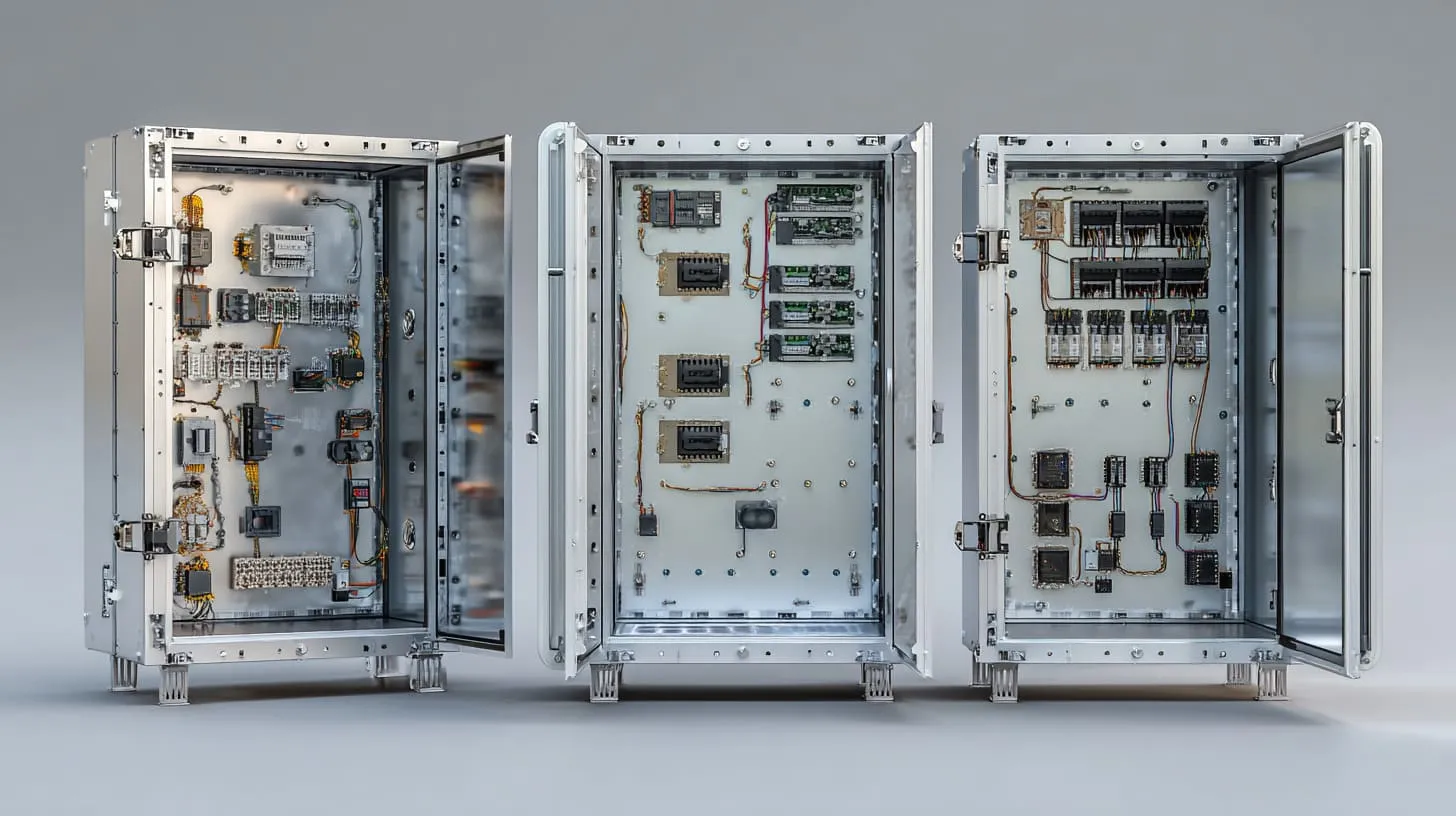
Aluminum works for EMI shielding because it is conductive. That conductivity lets it interact with electromagnetic energy in a useful way. It can reflect some energy. It can absorb and redirect some of it. It can also help create controlled return paths inside the enclosure system.
That sounds neat in theory. Real life is messier, but the basic principle still holds.
When I evaluate aluminum for shielding, I care less about how “metallic” it looks and more about how well current can move across the actual assembled surfaces. That small shift in thinking saves a lot of false confidence.
Electrical Conductivity and Reflection of Electromagnetic Waves
Conductive materials resist the spread of unwanted electromagnetic energy by reflecting part of it and carrying currents along the surface. Aluminum is not the most conductive metal in the world, but it is very good for enclosure use because it balances:
- good conductivity
- low weight
- easy machining
- reasonable cost
- good availability
That is why aluminum shows up so often in industrial housings, telecom boxes, controller cases, and instrument enclosures.
Skin Effect and Frequency-Dependent Shielding Behavior
At higher frequencies, current tends to travel near the surface of a conductor. This is called the skin effect. It matters because shielding is often strongly influenced by what happens right at the surface.
That point is easy to overlook.
If surface conductivity gets interrupted by an insulating oxide layer, coating, or bad contact area, shielding can drop even if the base metal underneath is still aluminum.
Thickness vs Conductivity: What Actually Matters More
A lot of people assume thicker metal always means better EMI shielding. Thicker metal can help in some situations, but conductivity and continuity usually matter first.
I have seen teams add thickness because it feels like a safe decision, while the real weakness stays right at the seam. That is like buying a thicker door while leaving the latch loose.
Here is how I usually think about it:
| Factor | Effect on EMI Shielding | My View |
|---|---|---|
| Conductivity | Very high | Often more important than extra thickness |
| Surface continuity | Very high | Critical at joints and seams |
| Wall thickness | Medium to high | Useful, but not the first thing I fix |
| Seam design | Very high | A weak seam can waste a good material |
| Openings/cutouts | Very high | Large openings reduce shielding fast |
Typical Shielding Effectiveness of Aluminum Enclosures
A well-designed aluminum enclosure can deliver strong shielding performance. But that sentence needs a warning label. The result depends on:
- seam design
- contact resistance
- opening size
- assembly pressure
- grounding strategy
- surface finish
So yes, aluminum can shield well. But now we reach the split that causes the real debate: what kind of aluminum surface are we actually talking about?
What Is Anodized Aluminum?
Anodized aluminum is aluminum that has gone through an electrochemical process to grow a thicker oxide layer on the surface. That surface layer improves corrosion resistance, wear resistance, and appearance. It also changes the electrical behavior of the part in a big way.
This is the part many buyers love for good reason. Anodized aluminum looks refined. It feels more finished. It resists scratches better than bare metal. It helps products look serious and stable.
Still, I get cautious when people choose anodizing too early in an EMI-sensitive project, because the exact feature that makes it attractive on the outside can create headaches in the shielding path.
The Anodizing Process Explained Simply
The aluminum part is placed in an electrolytic bath. Current passes through it. The surface grows a controlled oxide layer. That oxide becomes part of the part. It is not just paint sitting on top.
This matters because the surface change is real and durable.
Structure of the Oxide Layer (Al₂O₃)
The oxide on anodized aluminum is mostly aluminum oxide, often written as Al₂O₃. That layer is hard and stable. It helps protect the base metal underneath. It can also hold dye, which is why black anodized enclosures are so common.
But here is the issue for EMI work: aluminum oxide is not electrically conductive like bare aluminum.
That one fact changes the whole decision.
Key Properties: Corrosion Resistance, Hardness, Insulation
Anodizing brings several real advantages:
| Property | Benefit |
|---|---|
| Corrosion resistance | Better outdoor and humid environment performance |
| Surface hardness | Better scratch and wear resistance |
| Appearance | Clean, uniform, premium look |
| Electrical behavior | More insulating at the surface |
That last row is the one people do not talk about enough.
Types of Anodizing (Type II, Type III) and Their Differences
The two common types are:
Type II Anodizing
This is the more common decorative anodizing. It gives a clean finish and decent protection. It is often used for commercial housings and visible surfaces.
Type III Anodizing
This is hard anodizing. It creates a thicker and harder layer. It is tougher. It is also even more of a concern when you need reliable electrical contact through the surface.
A quick comparison helps:
| Type | Main Use | Surface Thickness | EMI Concern |
|---|---|---|---|
| Type II | Appearance and corrosion protection | Moderate | Can block conductive contact |
| Type III | Heavy wear and harsh use | Higher | Even more likely to interrupt contact |
Anodizing solves one set of problems well. It can create another set if the enclosure must behave like one conductive shielding body. That is why I need to put it beside bare aluminum, not just admire it from a distance.
What Is Bare Aluminum?

Bare aluminum is aluminum without a thick anodized finish. It still develops a thin natural oxide layer when exposed to air, but that natural layer is very different from a deliberate anodized coating in thickness and behavior during assembly.
Bare aluminum does not look as polished. It marks more easily. It can oxidize, stain, or change over time depending on the environment. But for EMI shielding, it often starts from a stronger electrical position.
What I pay attention to here is not beauty. It is whether the assembled case can keep a reliable conductive path without forcing extra process steps later.
Natural Oxide Layer vs Artificial Anodized Layer
All aluminum forms oxide naturally. That is normal. But natural oxide is thin. It is not the same as a deliberately grown anodized layer.
This distinction matters because people sometimes say, “Bare aluminum also has oxide, so there is no real difference.” That is too simple. In practice, the thicker and harder anodized layer is much more likely to disrupt contact unless the design accounts for it.
Electrical Conductivity Characteristics
Bare aluminum gives you much better direct surface conductivity than anodized aluminum. That makes it easier for:
- seam-to-seam contact
- lid-to-base contact
- hardware bonding
- grounding point preparation
- conductive gasket interaction
That does not mean bare aluminum is magically perfect. Surface cleanliness, pressure, joint design, and corrosion still matter. But it usually starts in a better place for shielding.
Advantages in Electrical Bonding and Grounding
If I need stable electrical contact across multiple enclosure parts, bare aluminum is often easier to work with. It reduces the number of places where I need to scrape, mask, machine back, or add conductive hardware just to restore basic continuity.
That can simplify the whole build.
| Bonding Aspect | Bare Aluminum | Anodized Aluminum |
|---|---|---|
| Seam contact | Easier | Harder |
| Ground point prep | Minimal | Often needs special treatment |
| Fastener contact reliability | Better | More variable |
| Conductive gasket compatibility | Better starting point | Needs more care |
Limitations: Corrosion, Wear, and Surface Instability
Bare aluminum is not free of trouble.
It can:
- scratch easily
- stain or dull over time
- corrode in harsh conditions
- look less premium
- change during handling and shipping
This is why the debate is real. EMI performance is not the only thing buyers care about. Many teams want both shielding and a surface that looks clean after months of use. That is exactly where anodizing starts pulling attention back.
But first, I need to show clearly what anodizing does to shielding performance.
How Does Anodizing Affect EMI Shielding Performance?
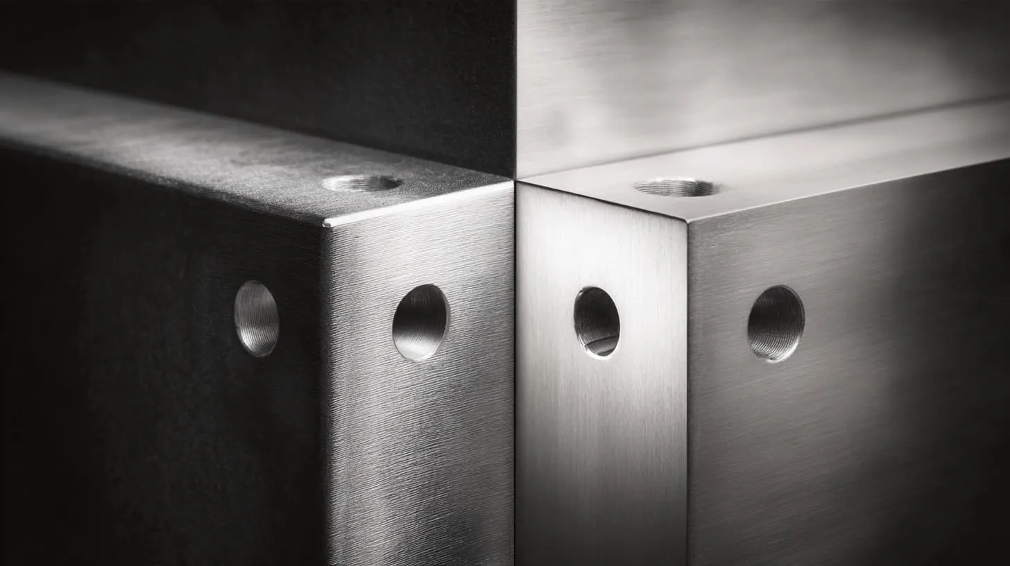
This is the heart of the article.
Anodizing affects EMI shielding because it changes the surface from conductive metal contact to an insulating oxide contact. That can interrupt current flow across seams, joints, fasteners, and grounding points. The enclosure may still be made of aluminum, but it no longer behaves like a continuous conductive body unless special steps are added.
I get suspicious the moment I hear, “The enclosure is all metal, so shielding should be fine,” because anodized surfaces can quietly break the path people assume is there.
Why Anodized Layers Are Electrically Insulating
Aluminum oxide is a poor electrical conductor compared with aluminum metal. That means an anodized surface can resist current flow where two enclosure parts meet.
So when a lid sits on a base, or a screw clamps two anodized parts together, the electrical contact may be weak, inconsistent, or almost absent depending on the geometry and pressure.
Impact on Surface Conductivity and Current Flow
EMI shielding depends on surface current flow, especially at higher frequencies. If the surface blocks that flow, energy can leak through weak points more easily.
This becomes very important at:
- enclosure seams
- screw holes
- connector panels
- cover joints
- grounding lugs
Contact Resistance at Mating Surfaces
A mating surface is where two parts touch each other. In shielding design, that touch is not just mechanical. It is electrical too.
If both sides are anodized, contact resistance can go up sharply. And once contact resistance rises, the enclosure stops behaving like one solid electrical shield.
Here is a simple comparison:
| Surface Condition at Joint | Contact Resistance Tendency | EMI Risk |
|---|---|---|
| Bare-to-bare contact | Low | Lower |
| Bare-to-anodized contact | Medium to high | Moderate |
| Anodized-to-anodized contact | High | Higher |
Real-World Issue: Broken Shielding Continuity Across Seams
I have seen projects where the body looked beautifully finished, but the seam performance told a different story. The housing passed visual inspection. It failed the deeper question: can current move cleanly across the assembly?
That is where many EMI issues begin.
A seam does not need to look open to be electrically weak. It only needs poor continuity.
Typical EMI Leakage Paths Caused by Anodized Surfaces
Common leakage paths include:
- lid-to-base joints
- door edges on cabinet-style enclosures
- screw-connected bracket interfaces
- connector mounting panels
- untreated ground points
- shield gasket areas with poor compression or poor surface prep
Here is a practical view:
| Leakage Path | Why Anodizing Causes Trouble |
|---|---|
| Lid seam | Oxide interrupts surface current path |
| Screw points | Screw pressure may not break through evenly |
| Panel edge | Contact area becomes electrically inconsistent |
| Ground lug area | Lug sits on insulating layer |
| Gasket contact zone | Gasket cannot make stable conductive bridge |
Once this problem is visible, bare aluminum starts to look less “unfinished” and more “honest” for EMI work.
How Does Bare Aluminum Perform in EMI Shielding?
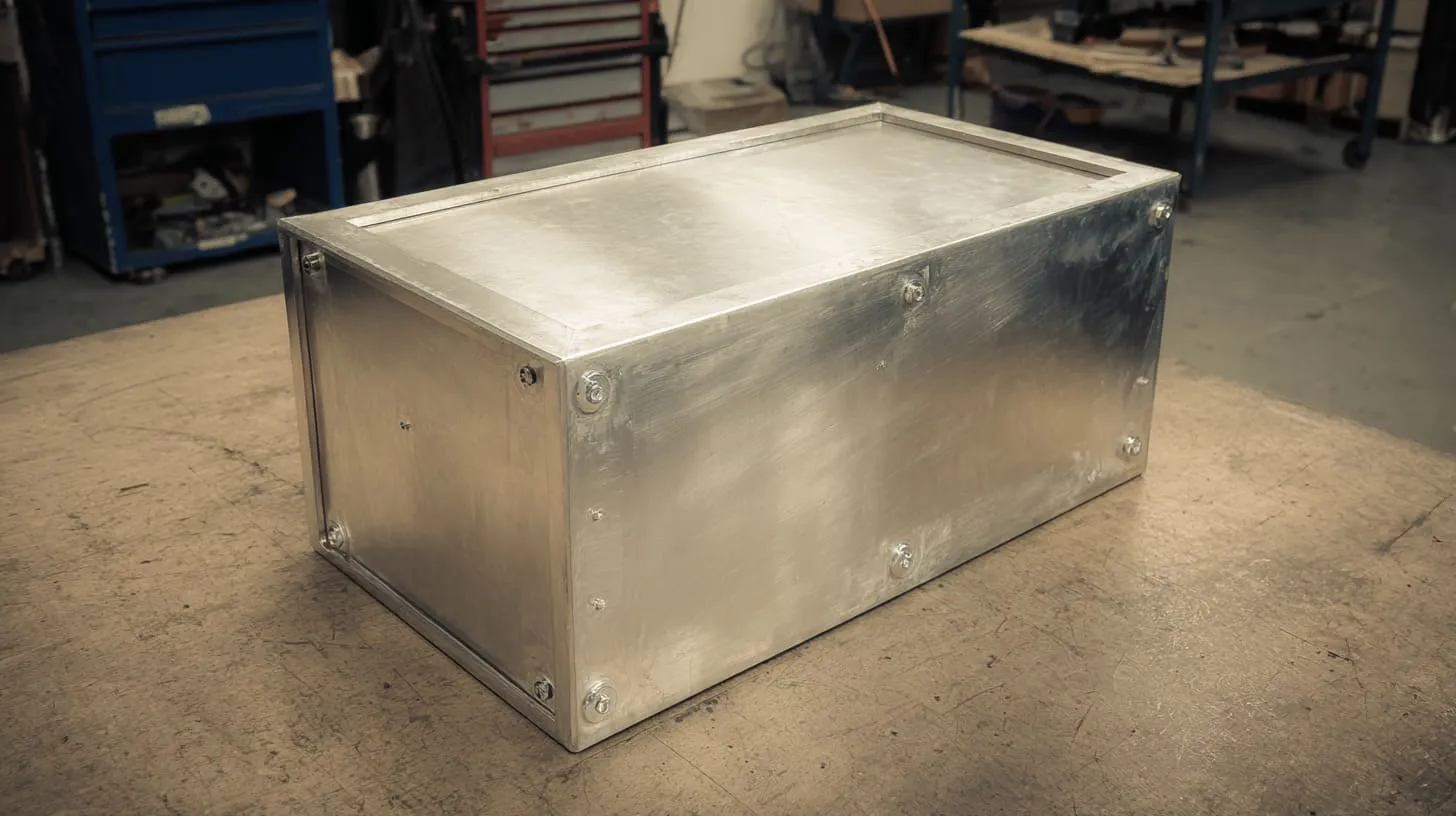
Bare aluminum usually performs better for EMI shielding because it supports more direct electrical continuity across the enclosure system. That helps the case act more like one conductive shell, not a group of separate parts pressed together and hoping for the best.
I trust bare aluminum more in EMI-sensitive builds when I know the design will depend heavily on seam contact, because it gives me fewer hidden electrical surprises during assembly.
Continuous Conductivity and Its Benefits
The big benefit is continuity.
With bare aluminum, current has a better chance to move across:
- cover joints
- folded seams
- mating flanges
- fastener contact areas
- bonding points
That makes shielding performance more stable, especially when the enclosure geometry is already pushing the limits.
Better Grounding and Bonding Performance
Grounding and bonding become easier when the surface is already conductive. You do not need as many workarounds to restore contact.
That can reduce:
- secondary machining
- masking steps
- field failures
- inconsistent assembly results
- unexpected test problems
Seam Conductivity and Enclosure Integrity
A seam is always a risk area. Bare aluminum does not remove that risk, but it gives the seam a better chance to perform.
Still, I never assume good shielding just because the parts are bare. I still check:
- seam flatness
- pressure distribution
- fastener spacing
- contact area width
- contamination on the surface
Bare aluminum gives you a stronger starting point. It does not excuse weak design.
Practical Shielding Effectiveness Compared to Anodized Parts
In many practical cases, bare aluminum will outperform anodized aluminum for shielding unless the anodized design uses special corrective measures.
A quick side-by-side view helps:
| Area | Bare Aluminum | Anodized Aluminum |
|---|---|---|
| Surface current flow | Better | Worse |
| Joint conductivity | Better | Worse |
| EMI seam behavior | More forgiving | More sensitive |
| Ground point setup | Easier | Often needs rework |
| Risk of hidden shielding weakness | Lower | Higher |
That sounds like a clean win for bare aluminum. But real products do not live in lab logic alone. They get assembled, coated, dropped, shipped, and used. That is where actual failure points show up.
Where Do Problems Actually Occur? (Real Engineering Failure Points)
EMI problems rarely come from a single dramatic flaw. Most of the time, they come from a collection of small weak points that look harmless on paper.
I have learned to worry more about ordinary details than fancy specifications, because the small contact points are often where shielding quietly falls apart.
Mating Surfaces (Lid-to-Base Contact Issues)
This is one of the biggest trouble spots.
If the lid and base do not make stable conductive contact, the enclosure loses shielding continuity around the seam. That problem gets worse when:
- both sides are anodized
- the flange is narrow
- the seam is not flat
- screw spacing is too wide
- compression is uneven
Fasteners and Screw Contact Reliability
People trust screws too much.
A screw can hold parts together mechanically while still giving poor electrical continuity. That is especially true if the surrounding surface is anodized, painted, dirty, or uneven.
I do not like depending on screw points alone for shielding unless I know the contact path has been intentionally designed, because random bite-through is not the same as reliable bonding.
Painted or Coated Internal Surfaces
Even inside the enclosure, coatings matter. A painted inside wall or coated bracket can interrupt electrical contact just like anodizing can.
This becomes a problem in:
- internal partitions
- shield cans
- board support brackets
- connector support plates
Gasket Interfaces and Shielding Gaps
Conductive gaskets help, but only when the surfaces around them are designed properly. If the gasket lands on a poorly prepared area, the result can look good and still perform badly.
Important gasket questions include:
| Question | Why It Matters |
|---|---|
| Is the compression even? | Uneven pressure causes weak contact |
| Is the landing area conductive? | Insulating surfaces ruin the gasket path |
| Is the seam flat enough? | Warped surfaces create gaps |
| Is the gasket material appropriate for the frequency range? | Wrong material gives poor results |
Case Study-Style Scenarios from Real Projects
I have seen a few patterns repeat.
Scenario 1: Premium black anodized housing, unstable EMI result
The case looked excellent. The team felt confident. But the top and bottom cover were both fully anodized, including the mating flanges. The enclosure needed local rework at contact areas before the test result improved.
Scenario 2: Bare aluminum prototype passes, finished product fails
This one hurts because it tricks the team. The prototype uses unfinished parts and passes pre-checks. The production version adds anodizing for appearance, and the EMI result gets worse. Same geometry. Different surface behavior.
Scenario 3: Conductive gasket added too late
The team adds a gasket after seeing leakage. But the contact lands on poorly prepared anodized surfaces. The gasket cannot rescue a bad electrical foundation.
Once people see failure points this way, the question becomes more balanced: can anodized aluminum still be used if the design is smarter?
Can Anodized Aluminum Still Be Used for EMI Shielding?
Yes, anodized aluminum can still be used for EMI shielding. But it usually cannot be treated as a “just anodize everything” decision. It needs design control. It needs planned conductive paths. It needs more discipline.
When I approve anodized aluminum for an EMI-related project, I only feel comfortable if the conductive contact areas are defined on purpose, not left to chance during assembly.
Selective Masking of Contact Areas
One common solution is to mask critical contact zones before anodizing. That keeps specific areas conductive.
Typical masked areas include:
- mating flanges
- ground points
- screw seating zones
- gasket landing surfaces
This gives you a nicer outer finish while protecting the electrical path where it matters most.
Removing Anodizing at Grounding Points
Another option is to machine, scrape, or otherwise remove anodizing at critical contact locations after finishing.
This can work, but it adds process complexity. It can also create inconsistency if the rework is not controlled well.
| Approach | Benefit | Risk |
|---|---|---|
| Mask before anodizing | Cleaner control | Needs good planning |
| Remove after anodizing | Flexible for late changes | Adds labor and variation |
Use of Conductive Gaskets (EMI Gaskets, Fingerstock)
Conductive gaskets can bridge gaps and improve seam shielding. Common options include:
- conductive elastomer gaskets
- metal fingerstock
- fabric-over-foam EMI gaskets
These are useful tools, but they are not magic. They still depend on decent contact geometry and surface prep.
Hybrid Designs: Anodized Exterior + Conductive Interior
Some projects use a mixed approach:
- anodized outside for appearance and corrosion protection
- bare or masked contact zones inside for electrical continuity
I think this is often the most sensible compromise for premium-looking industrial products that still need serious EMI control.
Trade-Offs Between Aesthetics and Performance
This is where the real business decision lives.
| Priority | Better Direction |
|---|---|
| Maximum EMI simplicity | Bare aluminum |
| Premium cosmetic finish | Anodized aluminum |
| Harsh wear conditions | Anodized aluminum |
| Easy seam conductivity | Bare aluminum |
| Balanced commercial design | Hybrid or selectively masked anodized design |
That trade-off becomes easier to see when both options are compared side by side without romance.
Bare Aluminum vs Anodized Aluminum: Direct Comparison for EMI
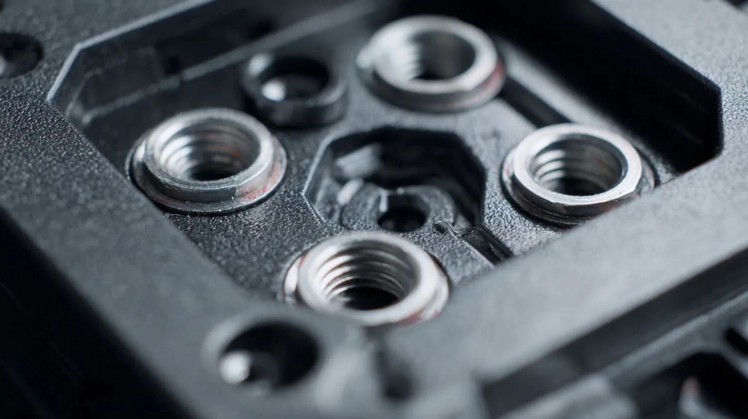
At this point, the simplest answer is this: bare aluminum is usually better for EMI shielding, while anodized aluminum is usually better for surface protection and appearance.
That sounds clean, but real buying decisions are never just one line long.
When I compare these two in real enclosure work, I do not ask which one is “better” in general. I ask which one is less likely to create the wrong problem for this specific product.
Conductivity Comparison
Bare aluminum wins here. Its surface supports better electrical contact and current flow.
Anodized aluminum loses here because the oxide layer acts as an insulator at the surface.
Shielding Effectiveness Comparison
If both designs are untreated and assembled the same way, bare aluminum usually gives better shielding continuity, especially across seams.
Anodized aluminum can still work, but usually only after masking, rework, or added conductive components.
Corrosion Resistance Comparison
Anodized aluminum clearly wins for corrosion protection.
Bare aluminum is more vulnerable to:
- oxidation changes
- staining
- handling marks
- harsh environment exposure
Durability and Wear Resistance
Anodized surfaces are harder and more scratch-resistant. Bare aluminum is softer and easier to damage visually.
Cost and Manufacturing Implications
This part is often overlooked. Bare aluminum may save you from some EMI-related process complications, but anodized aluminum may reduce cosmetic complaints and improve customer perception.
The “cheaper” choice can flip depending on whether you are paying for:
- rework
- masking
- EMI troubleshooting
- cosmetic quality control
- corrosion risk management
Here is the direct table again, because it deserves a clear look:
| Factor | Bare Aluminum | Anodized Aluminum |
|---|---|---|
| Electrical Conductivity | Excellent | Poor (insulating layer) |
| EMI Shielding | Strong | Weak (unless modified) |
| Corrosion Resistance | Moderate | Excellent |
| Surface Hardness | Low | High |
| Assembly Reliability | High | Risky without treatment |
And here is how I would summarize the comparison in plain words:
| If You Care Most About... | Better Choice |
|---|---|
| Raw EMI performance | Bare aluminum |
| Simple electrical bonding | Bare aluminum |
| Clean premium surface | Anodized aluminum |
| Better scratch resistance | Anodized aluminum |
| Mixed performance and cosmetics | Controlled hybrid design |
That comparison looks obvious once written down. Yet engineers still make the same mistakes around it.
What Do Engineers Usually Get Wrong?
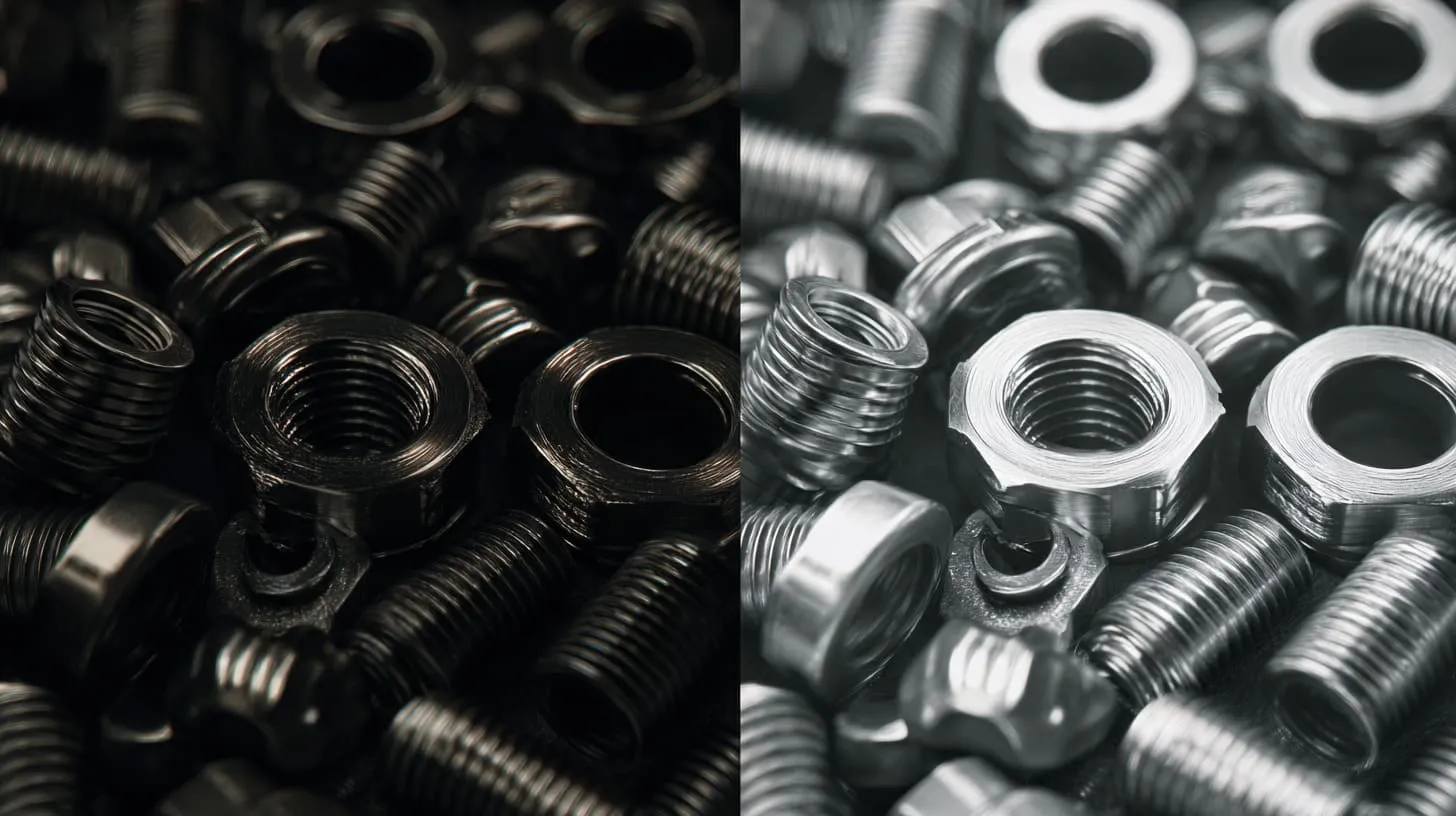
Most EMI mistakes around aluminum enclosures are not caused by ignorance. They are caused by assumptions that feel harmless.
That is what makes them dangerous.
The biggest warning sign for me is when a team speaks confidently about the material but vaguely about the contact path, because EMI problems often live inside that gap between material choice and actual assembly behavior.
Assuming “Metal = Conductive Everywhere”
This is probably the most common mistake.
A part can be metal underneath and still behave poorly at the surface. Anodizing, paint, powder coat, dirt, oxidation, and bad compression can all interrupt conductivity where it matters.
Ignoring Seam Resistance and Bonding Paths
People often focus on the wall material and forget the path across joints. But shielding is not just about the panel. It is about the whole enclosure acting together.
A seam with poor electrical contact can weaken an otherwise good design.
Over-Relying on Screws for Electrical Contact
I see this mistake often. Teams trust the screw to “fix it.” The screw holds the parts, yes. But holding and bonding are not the same thing.
A screw may:
- contact unevenly
- bite through coating in one place but not another
- loosen slightly over time
- give inconsistent results across builds
Treating Anodizing as Purely Cosmetic
Anodizing is not just color or finish. It changes the electrical behavior of the enclosure surface. Once people understand that, design discussions get much smarter.
Late-Stage EMI Fixes vs Early Design Thinking
Late fixes cost more.
A conductive gasket added late is more expensive than a seam designed well early. A masked contact path planned in CAD is easier than manual rework after finishing. A bare prototype that passes can mislead the team if the production surface changes later.
Here is a useful mistake map:
| Mistake | What Happens Later |
|---|---|
| Assuming all metal surfaces conduct equally | Hidden continuity issues |
| Ignoring seam design | Leakage at enclosure joints |
| Using full anodizing everywhere | Poor contact at key points |
| Trusting screws too much | Inconsistent EMI performance |
| Waiting for final test to think about shielding | Expensive redesign |
Once these errors are on the table, the next step is not theory. It is choice.
How to Choose the Right Option for Your Project?

There is no single answer that fits every project. The right choice depends on the EMI sensitivity, environment, appearance needs, corrosion risk, assembly method, and budget.
I make this decision by asking where failure would hurt most: test performance, field durability, or customer perception. That answer usually tells me which compromise is acceptable.
When Bare Aluminum Is the Better Choice
Bare aluminum is often the better choice when:
- EMI performance is a top priority
- seam continuity is critical
- grounding paths must stay simple
- the enclosure is internal or not customer-facing
- surface cosmetics are less important
- fast prototyping and electrical testing matter more than appearance
When Anodized Aluminum Still Makes Sense
Anodized aluminum can still make sense when:
- appearance matters a lot
- corrosion resistance matters a lot
- scratch resistance matters a lot
- the product sells in a premium visible market
- EMI needs are moderate and design controls are planned
- masked or conductive contact features can be added
Decision Framework Based on Environment and EMI Sensitivity
A simple table helps:
| Project Condition | Better Direction |
|---|---|
| High EMI sensitivity, many seams | Bare aluminum |
| Outdoor use, customer-visible housing | Anodized or hybrid |
| Fast electrical prototype stage | Bare aluminum |
| Premium branded product with EMI demands | Controlled anodized design |
| Low EMI concern, strong cosmetic demand | Anodized aluminum |
Cost vs Risk vs Performance Trade-Offs
This is where buyers need to stay honest.
Bare aluminum may look cheaper at first, but can lead to more cosmetic complaints.
Anodized aluminum may look more finished, but can create hidden EMI process cost.
So I try to compare the real cost, not just the part price:
- finishing cost
- masking cost
- assembly stability
- EMI troubleshooting time
- rejection risk
- field reliability
- visual quality expectations
Practical Checklist Before Finalizing Enclosure Design
Before I lock the direction, I like to ask:
- Is EMI shielding a critical pass/fail issue?
- Are the main seams expected to carry shielding continuity?
- Will the surface be customer-visible?
- Is corrosion exposure high?
- Can masked or machined contact areas be controlled well?
- Will the production line assemble this consistently?
That helps turn a vague material debate into a real engineering decision.
And once the choice is made, the design still needs discipline. Good shielding does not come from material alone.
Design Tips to Improve EMI Shielding Regardless of Material
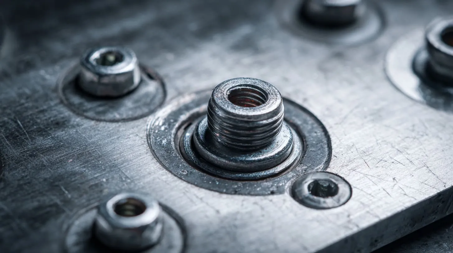
A weak design can waste a good material. A smart design can rescue a difficult one. That is why I never stop at “bare” or “anodized” as the whole answer.
The most useful habit I have learned is to follow the current path in my head before I approve the enclosure, because shielding problems often show up where the drawing looked innocent.
Ensure Continuous Conductive Paths
The enclosure should behave like a connected conductive system. That means thinking about:
- cover-to-body contact
- panel-to-frame contact
- bracket-to-wall contact
- shield can interfaces
- cable entry bonding points
Design Proper Mating Surfaces
Good mating surfaces should be:
- flat enough
- wide enough
- consistent
- properly compressed
- free from unwanted insulating layers at key points
A bad seam can ruin a great material choice.
Use Star Washers, Conductive Hardware
Hardware can help restore or improve contact, especially at selected points.
Useful tools include:
- star washers
- serrated washers
- conductive screws
- grounding studs
- dedicated bonding straps
These are not decorations. They are part of the electrical design.
Control Coating and Masking Strategy
If the product uses anodizing, paint, or powder coating, define exactly where coating is allowed and where conductivity must stay.
This is much better than hoping the assembly team will “make it work.”
Validate Early With Pre-Compliance Testing
I strongly prefer early testing over confident guessing.
A simple prototype check can reveal:
- seam leakage
- grounding weakness
- gasket failure
- bad contact assumptions
- production surface risks
Here is a practical design table:
| Design Action | Why It Helps |
|---|---|
| Keep conductive seam path continuous | Improves shielding integrity |
| Reduce unnecessary openings | Limits leakage |
| Use conductive hardware where needed | Improves bonding consistency |
| Define coating-free zones | Preserves electrical contact |
| Test before final finish release | Avoids expensive surprises |
Once those habits are in place, the final answer becomes easier to say without oversimplifying it.
Conclusion
If I only judge by EMI shielding performance, I will usually choose bare aluminum over anodized aluminum.
That is the honest answer.
Bare aluminum gives me better surface conductivity, easier bonding, and fewer hidden continuity problems across seams and joints. For pure shielding logic, it starts from a stronger position. Anodized aluminum, on the other hand, gives me better corrosion resistance, better wear resistance, and a more finished appearance. That is why it stays popular. It solves visible problems very well. It just does not solve EMI problems automatically.
So the real question is not “Which material is better?” The real question is “Which failure can this project tolerate less?”
If EMI is critical, I would lean toward bare aluminum or a carefully controlled hybrid approach. If appearance and durability matter just as much, I would still consider anodized aluminum, but only with planned conductive paths, masked contact areas, or proper EMI hardware. I would never treat it as a cosmetic choice only.
For me, the best enclosure decisions happen when the team thinks about shielding early, before the finish gets locked, before samples are approved, and before the first failed test makes everyone nervous.
If you are working on a custom enclosure project and you are not sure whether bare aluminum, anodized aluminum, or a mixed solution makes more sense, feel free to contact me. I can help you review the structure, surface treatment, and EMI risks before those small details turn into expensive delays.