Skip to content
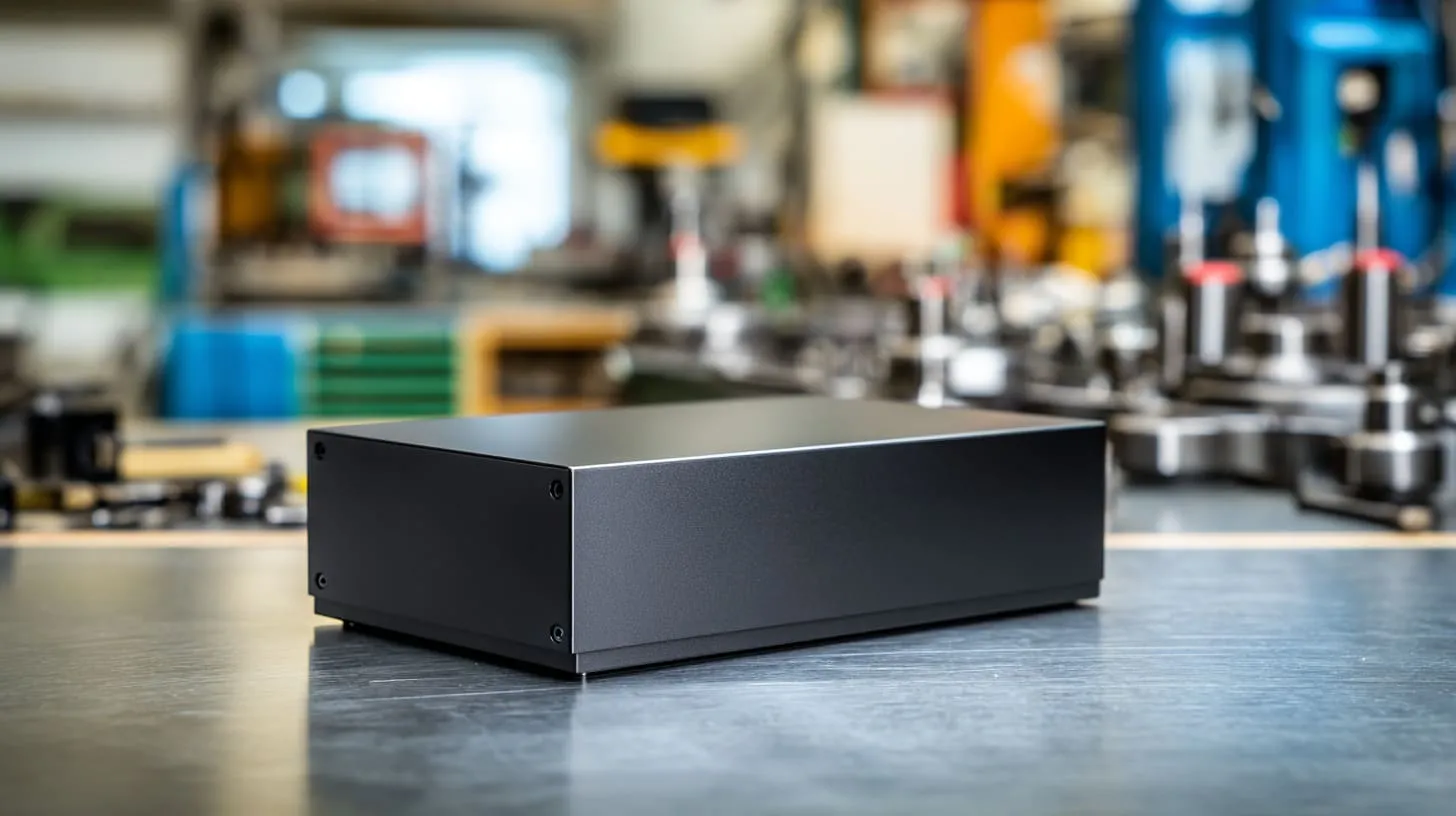
A neat aluminum enclosure can fool people very fast.
The edges are sharp. The finish looks premium. The color feels clean and modern. A black anodized case on a workbench often gives off the same signal: this product is already under control. I understand that reaction because I have had it too. Good anodizing makes an enclosure look serious. It also helps with corrosion resistance, wear, and brand image. For many industrial products, that matters a lot.
But this is also where the quiet trouble begins.
I have seen enclosures that looked excellent in sample photos and still caused real headaches later. The machining was fine. The logo position was right. The fit between top and bottom covers looked tight. Then the product went into testing, and the team found unstable grounding, poor bonding, or annoying EMC results that nobody expected from such a nice-looking housing. The problem was not the shape. The problem was the surface.
That gap between looks conductive and actually works electrically catches many designers.
Anodized aluminum is popular for good reasons. I use it often. I recommend it often too. Still, I do not treat anodizing as a harmless finish choice anymore. The moment electrical contact matters, I slow down and look at the design in a different way. A nice finish can help the product survive outside. The same finish can also block the electrical path the product needs inside.
What tends to mislead people is simple. Aluminum itself conducts electricity well. So people naturally assume an aluminum enclosure will also give easy electrical contact at the surface. That is not how anodizing works. The base metal is conductive. The anodized layer is not. That one detail changes many design decisions.
When I review a drawing, I do not judge the finish by appearance first. I judge it by asking one plain question: where exactly does this product need metal-to-metal contact, and what surface is sitting there now?
This guide is for designers, engineers, buyers, and product teams who want the enclosure to do both jobs well. I want to show where anodizing helps, where it causes risk, and how I think through those trade-offs before a problem appears in testing or production.
The surface may look calm. The electrical path underneath is often not. That is a good place to start.
A lot of problems begin with one wrong assumption, so the next step is to make the surface itself less mysterious.
What Is Anodized Aluminum and How Does It Work?

Anodizing sounds technical, but the basic idea is not hard.
It is an electrochemical process that changes the surface of aluminum. It does not just paint the surface. It grows an oxide layer from the aluminum itself. That point matters. A coating sits on top. Anodizing becomes part of the surface.
What is anodizing?
In simple terms, the aluminum part goes into an electrolyte bath. Current passes through it. The surface reacts and forms aluminum oxide. That oxide layer becomes thicker and more controlled than the thin natural oxide aluminum already has in air.
This is why anodized parts often feel more durable than raw aluminum. The surface gets better resistance to wear and corrosion. It can also hold dye well, which is why black, blue, red, and other colored finishes are common in electronics and enclosure work.
I like anodizing because it gives a clean and stable look without making the part feel cheap. A raw aluminum case can look unfinished. A good anodized case often looks complete.
Still, that same oxide layer has a second identity. It is not just protective. It is also electrically resistant.
Structure of anodized layer
Most people hear “oxide layer” and imagine one simple skin. In reality, it is more helpful to think of it in two parts.
| Layer Part | What it is like | Why it matters |
|---|---|---|
| Outer porous layer | Has tiny pores | Can absorb dye and sealing treatment |
| Inner barrier layer | Dense and tight | Creates strong electrical insulation |
The exact structure changes with process type, bath chemistry, current, and sealing, but for design thinking, this two-part view helps a lot.
The thickness also matters more than many people expect.
| Anodizing Type | Typical Thickness | Design Effect |
|---|---|---|
| Decorative anodizing | Around 5–25 μm | Good appearance and basic protection |
| Hard anodizing | Around 25–50+ μm | Better wear resistance, worse for electrical contact |
| Selective anodizing | Varies by masked area | Lets designers keep some contact zones conductive |
A few microns may sound tiny. On paper, it is tiny. In electrical contact, it can be the whole story.
Key properties of anodized aluminum
People usually choose anodizing for three main reasons:
- Corrosion resistance
- Wear resistance
- Better appearance
Those are all valid. I would add one more line to that list every time:
- Electrical insulation
That fourth point is where many enclosure problems begin. The finish that protects the part can also isolate it.
I have talked with buyers who focused heavily on color, salt spray performance, and scratch resistance. Those are fair concerns. But if the housing also needs grounding continuity across panels, lids, brackets, or mounting points, the discussion has to widen. A strong finish is not automatically a smart finish for every contact area.
This is where I often see design reviews become more honest. Everyone likes the finish until someone asks how the current is supposed to move through it.
So the next question becomes very direct: does anodized aluminum actually conduct at the surface, or does it only look like it should?
Is Anodized Aluminum Conductive?
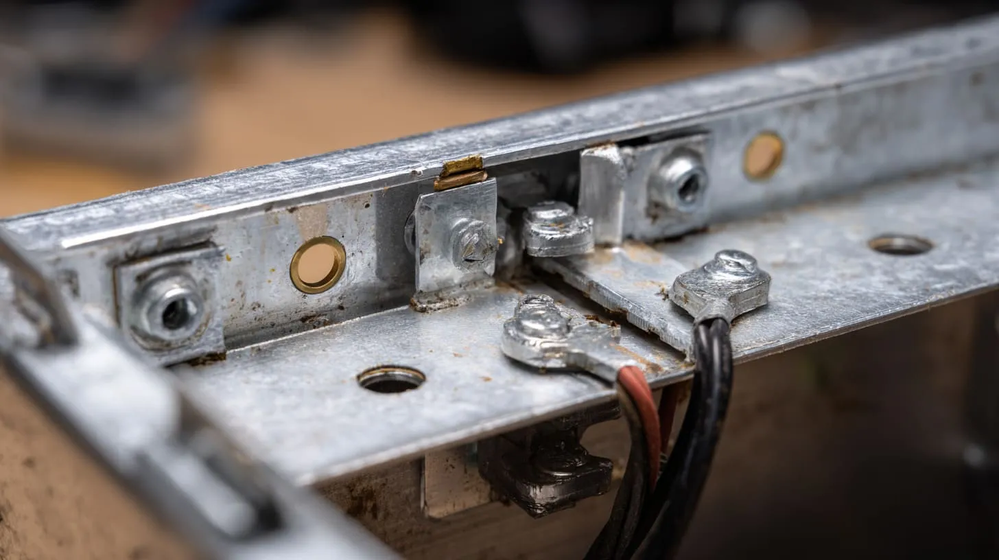
This question sounds simple. The answer needs one careful split.
Aluminum is conductive. Anodized aluminum, at the surface, is mostly not.
That difference has confused many good engineers, not because they do not understand materials, but because the part is still aluminum underneath. The metal is there. The conductivity is there too. It is just blocked by the oxide layer sitting on top.
Conductivity of base aluminum vs anodized surface
Raw aluminum has good electrical conductivity. That is one reason it is used in so many industrial and electrical products. If I machine a fresh bare aluminum contact point and clamp it correctly, I can often get a low-resistance connection.
Anodized surfaces behave very differently.
| Material Condition | Surface Conductivity | What I expect in contact |
|---|---|---|
| Bare aluminum | Good | Possible low-resistance path if joint is designed well |
| Light anodized aluminum | Poor | Contact becomes uncertain or weak |
| Hard anodized aluminum | Very poor | Contact is usually unreliable without special design |
This is why I do not let anyone use the words aluminum and conductive too casually in the same sentence. That shortcut creates expensive mistakes.
Why anodized surfaces block electrical contact
Aluminum oxide is a dielectric. In plain language, it acts like an insulator.
Even a thin anodized layer can raise contact resistance a lot. The problem is not only that the path becomes worse. The problem is also that it becomes less predictable. One screw may bite enough to make partial contact. Another may not. One assembly may pass a bench check. Another may fail after vibration, time, or humidity exposure.
That unpredictability is often worse than a clean failure.
I can work with a clearly non-conductive design because I know I need a different bonding solution. A half-conductive design is harder. It gives false confidence. It passes just enough early checks to delay the real fix.
What makes this tricky is that pressure sometimes hides the issue for a while. Parts look tight. Assemblies feel solid. The resistance path still is not stable.
When can anodized aluminum still conduct?
It can conduct when the oxide layer is removed, broken, penetrated, or intentionally avoided.
That can happen in a few ways:
- A masked area leaves bare aluminum exposed
- A serrated washer cuts through the oxide
- A stud, boss, or fastener design creates controlled penetration
- A machining step removes anodizing at a critical zone
- A different surface treatment is used where conductivity matters
But I do not like relying on luck here. Random penetration is not the same as engineered contact. A screw that scratches the surface during assembly might create contact today and lose consistency later.
I tend to get suspicious when someone says, “It should be fine because the screw is tight.” Tight is a mechanical word. Reliable contact is an electrical result. Those are not always the same thing.
Once that becomes clear, the whole enclosure discussion changes. The next issue is not abstract anymore. It becomes about grounding, bonding, EMI, and whether the product will behave well in the real world.
Why Electrical Contact Matters in Enclosure Design
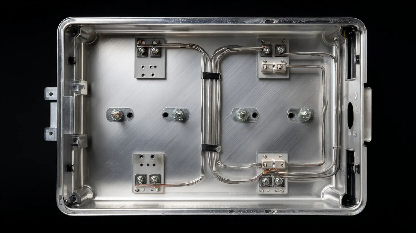
Electrical contact inside an enclosure is not a small side topic.
For many products, it affects safety, EMC behavior, noise control, signal stability, and long-term reliability. A housing is not always just a shell. Sometimes it is part of the electrical strategy, whether the designer meant it to be or not.
Grounding vs bonding: what designers need to know
These two words get mixed together all the time.
Grounding usually means connecting to a reference point or safety earth, depending on the product. Bonding means creating electrical continuity between conductive parts so they stay at the same potential and provide a stable path.
I think this table helps keep the discussion clean:
| Term | Main purpose | Common design concern |
|---|---|---|
| Grounding | Safety or reference | Where does current return or discharge go? |
| Bonding | Continuity between metal parts | Do panels, covers, brackets, and chassis stay electrically connected? |
An enclosure can fail at bonding even when the grounding concept looks correct on a schematic. That mismatch causes a lot of confusion. The board team thinks the grounding plan is complete. The mechanical team thinks the enclosure is all metal, so it should be fine. Testing says otherwise.
The truth sits in the joints.
Impact on EMC performance
A poorly bonded enclosure can leak EMI through seams, panel breaks, lid joints, or badly connected sub-parts. That matters even more in products with switching power, digital noise, radio modules, motors, or sensitive sensing circuits.
I have seen projects where the enclosure looked premium and still acted like a loose cage. The shell was metal, yes. But the electrical continuity across its sections was weak. So the enclosure did not behave like one consistent shield.
This is one of those design moments where appearance can be deeply misleading. I trust meter readings more than I trust a beautiful black finish.
Real-world failure modes
The failure is not always dramatic. Often it shows up in annoying, slippery ways.
| Failure Mode | What it looks like in real work | Why it happens |
|---|---|---|
| Intermittent grounding | Problem comes and goes | Contact depends on pressure or vibration |
| High contact resistance | Unexpected voltage drop or poor bonding check | Oxide layer blocks current |
| EMC test issues | Emissions or susceptibility failures | Seams and joints do not conduct well |
| Noise instability | System behaves differently in some setups | Return path is weak or inconsistent |
| Field reliability drift | Product works at first, weakens later | Joint changes over time with wear, oxidation, or movement |
That last one bothers me most. A product that fails immediately gets fixed. A product that works for two months and then becomes unstable creates blame, email chains, and expensive doubt.
At that point, the natural question is painful but useful: if the risk is so common, what exactly do designers keep getting wrong?
Common Mistakes Designers Make with Anodized Aluminum

Most mistakes here do not come from carelessness.
They come from reasonable assumptions that happen to be wrong in this specific material system. That is why the same problem shows up again and again in enclosure work.
Assuming screws automatically create good contact
This is probably the most common one.
A screw clamps parts together. That is true. A screw may also scratch or cut the anodized layer. That is also true. But neither of those facts guarantees stable electrical contact.
A small contact point can be unstable. A tiny cut-through area can vary from one unit to the next. A painted or anodized surface under the head can still block most of the path.
| Assumption | What actually happens |
|---|---|
| Tight screw means good bonding | Tight screw may only mean strong clamping |
| Metal screw into metal part guarantees conduction | Surface finish can isolate the joint |
| One successful sample proves the design | Sample luck does not equal production stability |
What often changes my mind fastest is not whether the screw “touches metal,” but whether the contact area is controlled, repeatable, and still likely to work after shipping and use.
Ignoring coating thickness in design
Not all anodizing behaves the same way.
A thin decorative anodized finish and a thick hard anodized finish do not create the same contact behavior. If the project asks for stronger wear resistance, the finish may get thicker. That can be good for durability and worse for electrical continuity.
I have seen teams upgrade the anodizing spec to make the product feel more premium, then accidentally make the bonding path more difficult. Nobody was trying to make a mistake. They were just solving one problem while creating another.
Relying on assembly pressure alone
Pressure helps. It does not solve everything.
A fresh assembly can feel reassuring. The fasteners are tight. The enclosure seams look clean. But pressure changes over time. Temperature changes parts. Vibration moves joints. Tiny wear marks shift the path. Humidity and contamination add their own surprises.
If the whole contact plan depends on “press hard and hope,” I get nervous.
Overlooking environmental factors
A bench test in a quiet room is not real life.
Products move. They warm up. They cool down. They ship. They vibrate. They sit in damp rooms. They go into cabinets near switching equipment. They get opened and reassembled.
| Environment Factor | Why it matters for contact |
|---|---|
| Humidity | Can worsen surface changes and instability |
| Thermal cycling | Expands and contracts joints |
| Vibration | Weakens marginal contact paths |
| Reassembly | Changes scratch pattern and pressure condition |
| Outdoor exposure | Adds corrosion and contamination risk |
This is where I stop thinking like a drawing reviewer and start thinking like the product’s future user. A joint that barely works in ideal conditions is not a real solution.
Once those mistakes are visible, the design conversation becomes much more practical. Then we can stop guessing and start building proper contact on purpose.
How to Ensure Reliable Electrical Contact on Anodized Parts
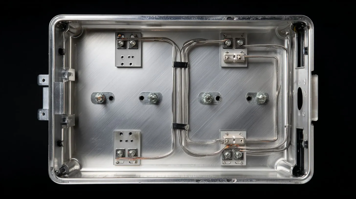
The good news is this problem is very solvable.
I do not avoid anodized aluminum just because contact matters. I simply stop treating the finish and the electrical path as separate topics. When the design handles both together, the result can look good and work well.
Masking critical contact areas
This is one of the cleanest solutions.
If a specific point must conduct, I often prefer to leave that point bare instead of forcing hardware to fight through the anodized layer later. That can be done by masking the area before anodizing or by defining no-anodize contact zones in the drawing.
Typical masked areas include:
- Ground lug locations
- Lid-to-body bonding pads
- Stud or boss contact surfaces
- Internal bracket mounting zones
- Shielding seam contact strips
| Contact Area Type | Why masking helps |
|---|---|
| Ground terminal area | Gives direct metal-to-metal contact |
| Chassis seam zone | Improves continuity across enclosure sections |
| Bracket mount point | Prevents floating internal metal parts |
| Fastener seating area | Reduces dependence on random penetration |
I usually trust a deliberate bare contact patch more than a “strong enough screw.” It is simpler to explain, easier to inspect, and easier to repeat in production.
Mechanical penetration methods
Sometimes masking is not possible or not enough. Then mechanical penetration can help.
Star washers, serrated washers, and certain hardware designs are made to bite through surface layers. They create local penetration and improve the chance of contact. This can work well when the geometry, pressure, and assembly process are controlled.
Still, I do not treat them like magic. They are tools, not excuses.
A washer that bites through at one point may still leave the rest of the joint electrically poor. That is why I look at the whole path, not just the fastener hardware.
Dedicated grounding features
A product gets more reliable when the contact path has a home.
Grounding bosses, threaded studs, PEM fasteners, and planned bonding tabs give the design a more stable electrical structure. They tell production where the current path is supposed to live. That reduces random behavior.
| Feature | Main benefit | Best use case |
|---|---|---|
| Grounding stud | Stable dedicated connection point | Chassis grounding |
| PEM fastener | Repeatable hardware interface | Production consistency |
| Bonding tab | Clear seam continuity path | Lid or panel bonding |
| Contact boss | Strong localized pressure zone | CNC or cast parts |
When I see a design with dedicated contact features, I usually feel more relaxed. It tells me the electrical path was designed, not discovered by accident during assembly.
Surface treatment alternatives
Sometimes the best fix is not better hardware. Sometimes it is a different finish strategy.
Options can include:
- Selective anodizing
- Conductive conversion coatings
- Conductive plating on critical parts
- Mixed-finish designs with conductive contact zones
- Bare machined internal contact strips plus anodized visible surfaces
This is often where cost, looks, and function start arguing with each other. That is normal. A beautiful enclosure is valuable. So is a product that passes testing without drama.
The smartest answer is often not “anodize everything” or “avoid anodizing completely.” It is a mixed decision, made zone by zone.
Once those contact features exist, the next challenge is bigger: how do I design the whole bonding path so the enclosure behaves like one intentional system?
Design Strategies for Grounding and Bonding
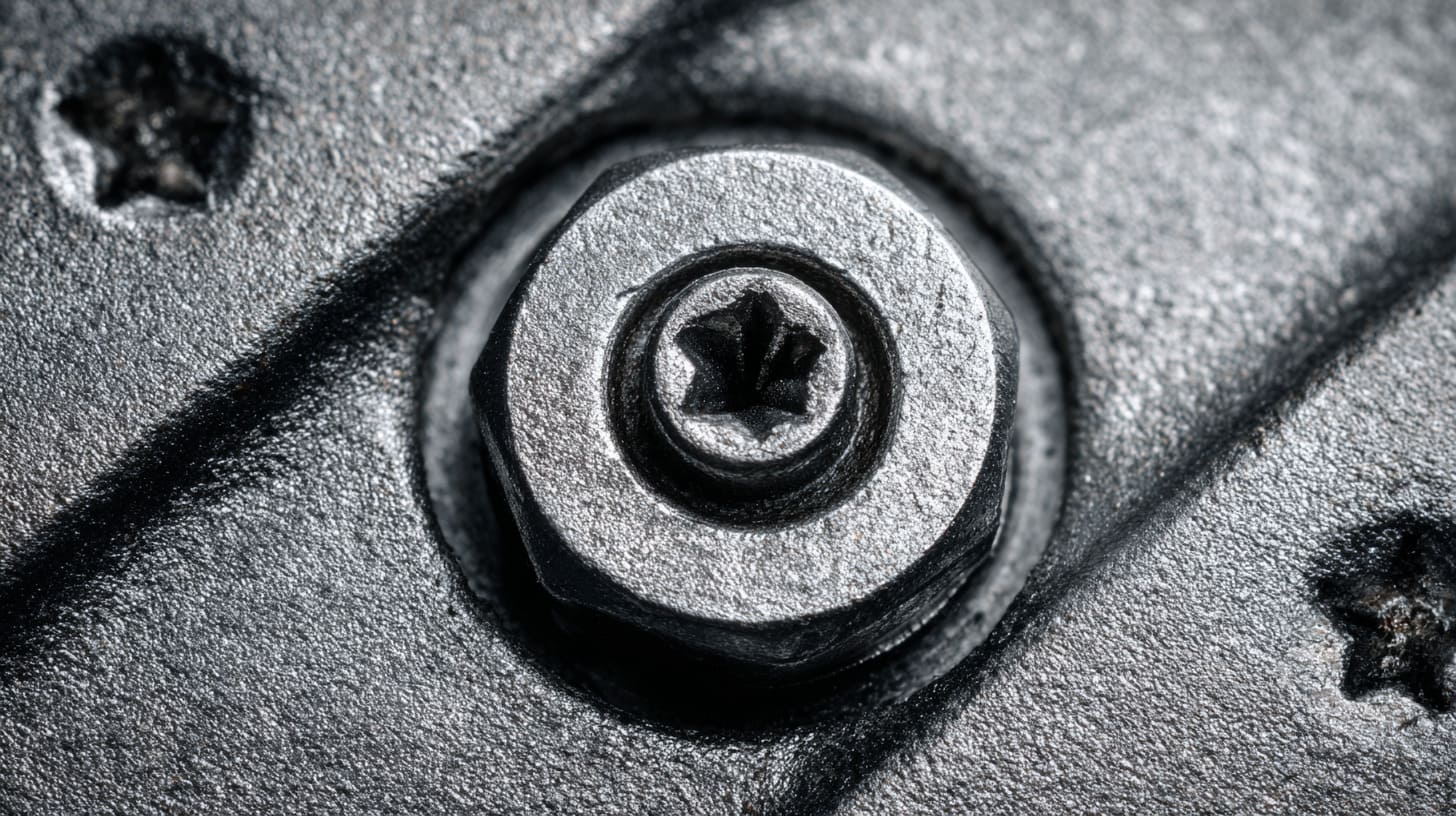
A good contact point is helpful. A good contact path is better.
This is where I see mechanical design become much more mature. The issue is no longer one washer or one screw. The issue becomes how the full enclosure handles current flow, continuity, and shielding behavior.
Designing for low-resistance paths
Short and direct paths usually behave better.
If current or bonding continuity has to travel through several panels, brackets, screws, and seams before reaching its destination, every joint adds another chance for trouble. That does not mean complex designs are always wrong. It means every joint should earn its place.
I become cautious when a design depends on too many separate metal interfaces just to maintain basic continuity. Complexity in the current path tends to charge interest later.
A simpler path is easier to inspect, easier to test, and easier to keep stable over time.
Using grounding straps or braids
Flexible grounding straps or copper braids can solve problems that rigid joints do not handle well.
They are useful when:
- A lid opens and closes
- A door moves
- Vibration is expected
- A bracket may shift slightly
- The main metal path is interrupted by finish or mechanical tolerance
| Option | Strength | Limitation |
|---|---|---|
| Rigid metal joint | Simple and compact | Less tolerant of movement |
| Ground braid | Flexible and reliable | Adds parts and assembly steps |
| Ground strap with lugs | Easy to define electrically | Needs careful hardware selection |
I like braids when movement is real, not theoretical. They may look less elegant than a hidden screw joint, but they often behave more honestly in the field.
Multi-point grounding vs single-point grounding
This part depends on product type.
A single-point approach can help control some noise issues in certain systems. A multi-point approach can improve shielding and enclosure continuity in others. The right answer depends on frequency, layout, system architecture, and failure risk.
| Strategy | Good side | Risk side |
|---|---|---|
| Single-point grounding | Can reduce some loop concerns | May leave enclosure sections weakly bonded |
| Multi-point grounding | Better continuity and shielding in many enclosure cases | Can create unwanted complexity if done carelessly |
I do not pick this by habit. I pick it by asking what the enclosure is really doing in the product. Is it mostly mechanical protection? Is it part of shielding? Is it tied to sensitive electronics? Is there a noisy power stage nearby? Those questions matter more than slogans.
Testing contact resistance during development
This is one of the least glamorous and most valuable steps.
A milliohm check across critical joints can reveal a weak design before it becomes a production problem. Pre-compliance EMC testing can do the same on a larger level. Neither step is perfect. Both are far cheaper than learning the lesson late.
I pay more attention to repeated measurements across several builds than to one good number from one lucky sample.
That is because repeatability is the real test. A product that works once is interesting. A product that works the same way across builds is ready.
Once the path is designed and tested, finish choice becomes less emotional. Then we can compare surface treatments with a cooler head.
Comparing Surface Finishes for Electrical Contact
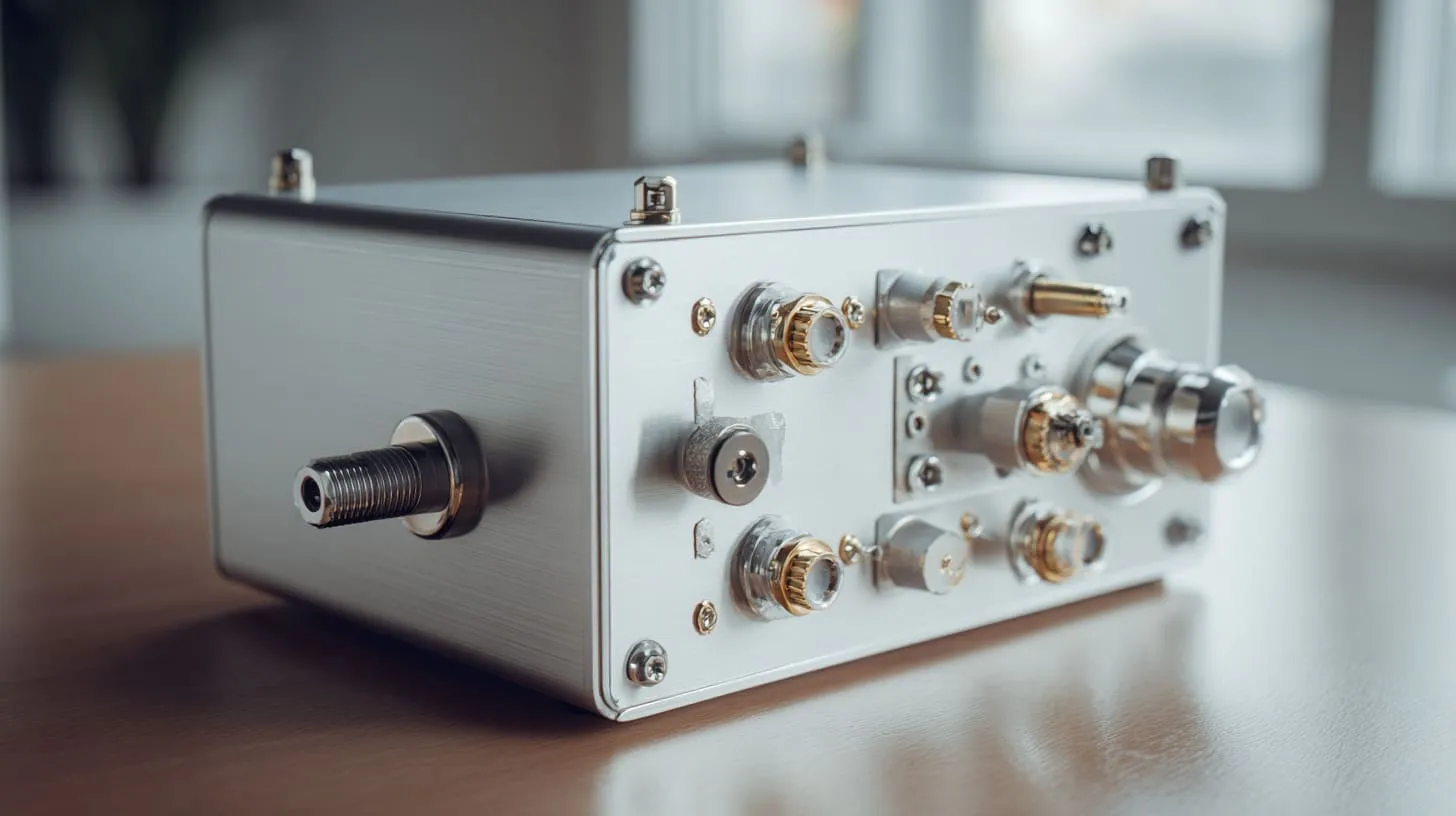
Surface finish decisions often start with looks, corrosion resistance, or cost.
That makes sense. Buyers see the finish first. End users touch the finish first. But for electrical contact, the finish also changes the behavior of the whole enclosure. So I never compare finishes by appearance alone.
Anodizing vs powder coating vs plating
Here is a simple working comparison:
| Finish Type | Conductivity | Durability | Typical Use Case |
|---|---|---|---|
| Anodizing | Poor at surface | High | Aesthetic parts, corrosion resistance, wear resistance |
| Powder coating | Very poor | High | Protection and appearance only |
| Conductive plating | Good | Medium | Electrical contact and shielding needs |
| Bare aluminum | Good at first | Low to medium | Internal contact zones, controlled environments |
| Conductive conversion coating | Better than anodizing for contact use | Medium | Functional electrical areas |
Powder coating is usually even worse than anodizing for contact because it acts like a thicker barrier. It protects well, but it does not help conduction. Conductive plating can help electrically, but it brings its own cost, process limits, and appearance trade-offs.
When anodizing is still the right choice
Anodizing is still a very smart choice in many projects.
It works well when:
- The product needs corrosion resistance
- The product will be touched often
- Appearance matters a lot
- Wear resistance is important
- Electrical contact can be designed at specific controlled points
I do not avoid anodizing just because conductivity matters. I avoid lazy assumptions around anodizing.
When to avoid anodizing
Some projects should step back and rethink the finish.
Examples include:
- Enclosures with strong EMC sensitivity
- Products that need broad conductive seams
- Designs with many contact joints and few controlled bonding points
- Cases where maintenance or reassembly may change contact stability
- Systems where reliable shielding depends on large-area metal continuity
This is one of those moments where I try not to fall in love with the finish sample. A surface can be beautiful and still wrong for the job.
Once the finish decision becomes realistic, the engineering work gets easier. Then the next step is to turn the whole topic into something practical and repeatable.
Practical Design Checklist for Engineers
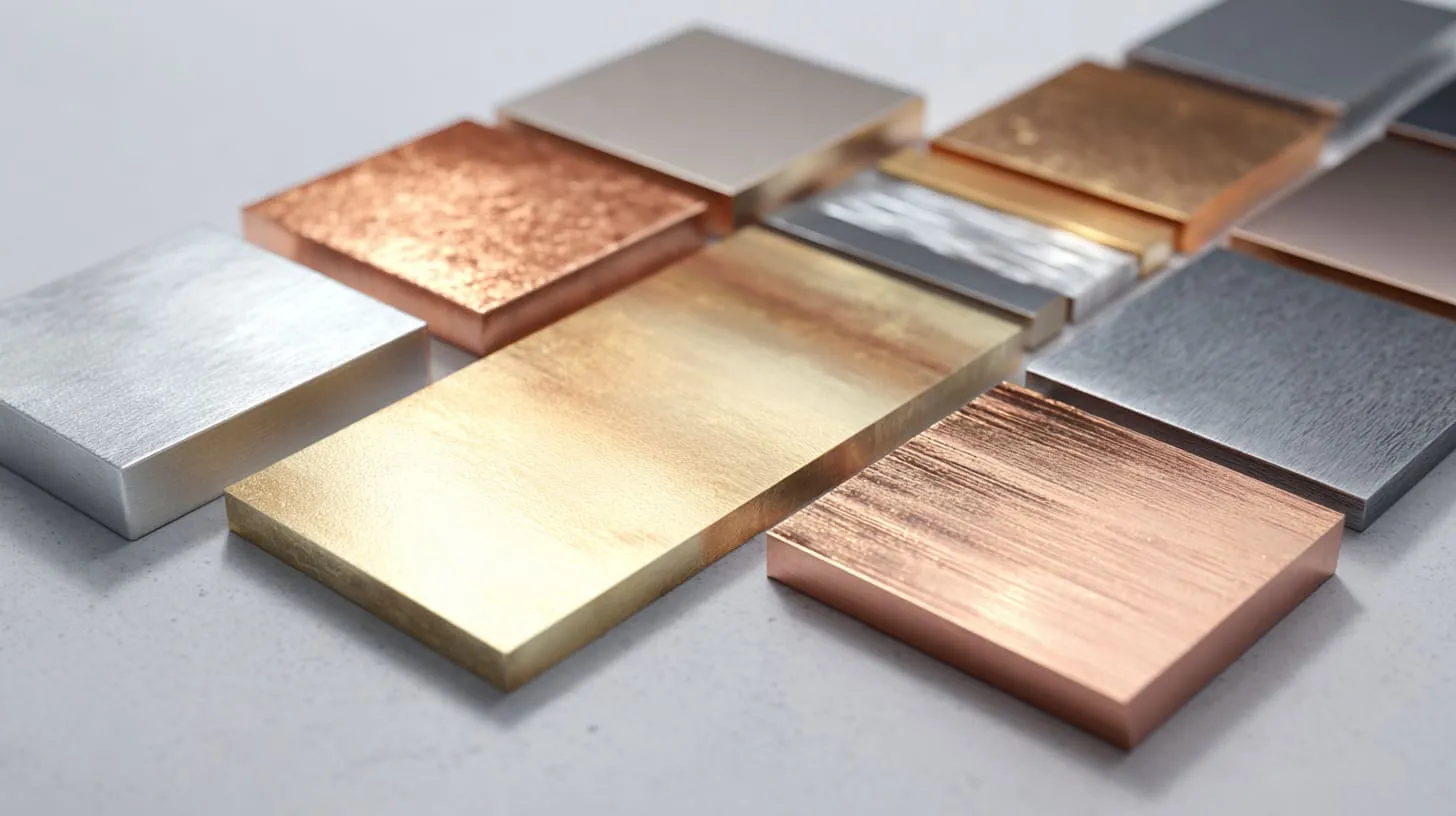
I like theory, but drawings move faster when the team can work from a practical checklist.
This topic becomes easier when I break it into stages. That keeps the discussion grounded and stops the finish choice from drifting into vague opinions.
Before design finalization
I want clear answers to these questions first:
- Where does the product need real electrical continuity?
- Which enclosure parts must bond to each other?
- Which points are only structural, not electrical?
- Does the enclosure contribute to shielding performance?
- Which areas can stay anodized, and which cannot?
At this stage, I try to find hidden assumptions. A silent assumption in the design phase is often the most expensive part later.
During design
This is where intent becomes geometry.
| Design Item | What I want to see |
|---|---|
| Contact zones | Marked clearly on drawing |
| Masked areas | Defined with size and location |
| Fastener hardware | Chosen for both mechanical and electrical function |
| Bonding path | Short, direct, and visible in design review |
| Finish notes | Clear about where anodizing is allowed or blocked |
I do not like vague notes like “ensure grounding” with no physical detail. If the drawing cannot show me where the contact lives, the factory will have to guess.
During prototyping
Prototype stage is where optimism meets the meter.
I usually want:
- Contact resistance checks
- Assembly repeatability checks
- Reassembly checks after opening and closing
- Basic vibration thinking if the application needs it
- EMC pre-checks if the product is sensitive
| Prototype Check | Why I care |
|---|---|
| Resistance across seams | Shows if contact is real |
| Contact after reassembly | Shows if the design is stable |
| Visual inspection of bite-through areas | Shows if hardware is doing what was expected |
| Pre-compliance EMC | Finds weak enclosure behavior early |
Before mass production
This final stage is less glamorous, but it saves pain.
I want to know:
- Can the anodizing process hold the same quality lot after lot?
- Are masked areas staying clean and controlled?
- Is hardware installed the same way every time?
- Is the assembly process strong enough to keep contact repeatable?
- Are inspection points clear for QC?
The detail I worry about most before release is not the best sample. It is the average unit from a busy production day.
That is usually where good engineering turns into good manufacturing. And that leads directly to one more truth many buyers overlook: the supplier has a real role in getting this right.
How Manufacturers Can Support Better Electrical Design
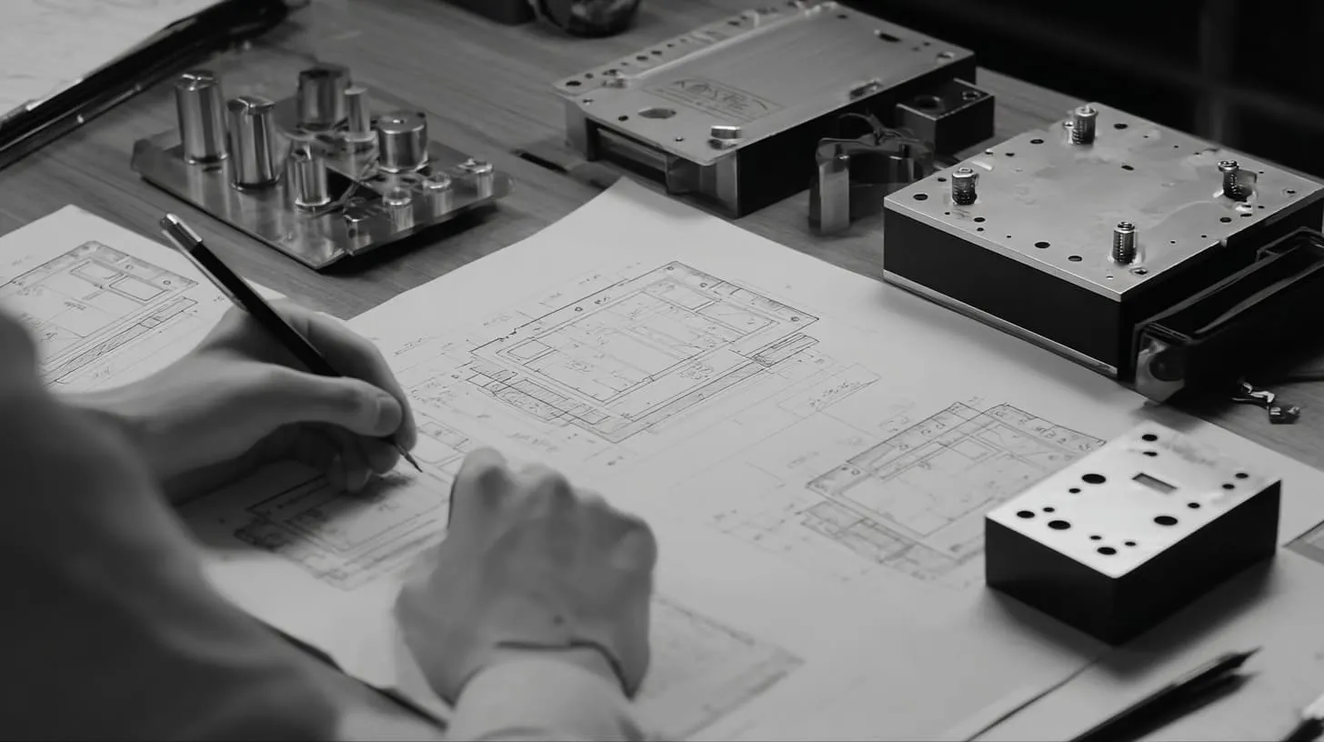
A good factory can improve this kind of design a lot. A weak factory can hide the problem until it hurts.
I say that carefully because I work in manufacturing myself. I know how often the factory sees the risk before the customer does. I also know how often that warning is not explained clearly enough.
Communication between engineer and factory
The drawing should not leave critical contact areas to interpretation.
I prefer to see things like:
- Masked contact zones marked clearly
- Bonding points named in the notes
- Hardware type specified
- Finish boundaries defined
- Test expectations discussed before sampling
| Communication Topic | Why it matters |
|---|---|
| Grounding area callout | Prevents full anodizing on needed contact point |
| Hardware note | Stops cheap substitutions |
| Assembly intention | Helps the factory understand why the joint matters |
| Test method | Aligns sample review with real function |
A supplier may machine exactly what the drawing says and still deliver the wrong electrical result if the design intent was never made explicit.
Custom solutions from enclosure suppliers
This is where a capable supplier can help more than people expect.
For example, a supplier can suggest:
- Selective anodizing instead of full anodizing
- Pre-installed grounding studs
- Better washer or fastener choices
- Bare internal contact surfaces with anodized outer faces
- Simpler bonding paths through small geometry changes
I have seen small changes in hardware location solve problems that looked serious at first. Sometimes the fix is not expensive. It is just specific.
Balancing cost vs performance
Every project has a budget. That is normal.
Still, I do not think the cheapest finish route is always the lowest-cost decision. A fully anodized beautiful sample that creates EMC trouble can become much more expensive than a slightly smarter design with a few masked zones or contact features.
The projects I respect most are not the ones that maximize one feature. They are the ones that know where to spend and where not to.
That balance is what separates a clean-looking enclosure from a reliable one. And once that is clear, the conclusion becomes much simpler than people expect.
Conclusion

Anodized aluminum is useful for many enclosure projects. I use it often because it gives real value. It improves corrosion resistance, wear resistance, and appearance. For many industrial and electronic products, those are strong reasons to choose it.
But I do not let those strengths hide the electrical truth.
The aluminum underneath conducts well. The anodized surface does not. That means electrical contact cannot be assumed. It has to be planned. If the product needs grounding, bonding, shielding continuity, or stable low-resistance joints, the drawing needs to show exactly how that will happen.
Throughout real work, I have found that small details decide the result. A masked contact pad. A better washer. A dedicated grounding stud. A shorter bonding path. A better conversation between the engineer and the factory. None of those things look dramatic on paper. All of them can decide whether the enclosure behaves well or causes slow, frustrating trouble.
If I had to reduce this whole topic to one working idea, it would be this: I never judge anodizing by finish quality alone when the enclosure also has an electrical job to do.
That is where good design becomes honest.
If you are working on a custom aluminum enclosure and want to avoid surprises in bonding, grounding, or EMC behavior, I suggest reviewing the contact points before you lock the finish. If you want, you can send me your drawing or enclosure concept, and I can help you check where anodizing should stay, where it should stop, and how to make the design easier to manufacture well.