Skip to content
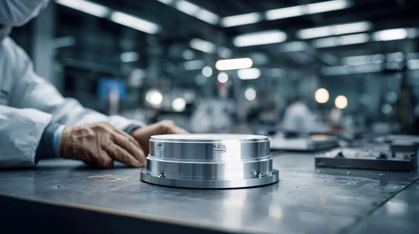
Metal-to-metal contact sounds like one of those ideas that should always work.
I understand why so many engineers trust it. Metal touches metal. Current flows. EMI leakage drops. The logic feels clean. It feels solid. It also feels a little comforting, because simple answers are easy to defend in meetings.
But I have seen this idea go wrong enough times that I no longer accept it at face value.
A metal enclosure can look excellent on the bench. The machining is clean. The lid fits nicely. The screws sit flat. The surface finish looks serious and expensive. Everyone in the room feels calm. Then the product goes into testing, or worse, into the field, and the result tells a different story. The contact that looked “good enough” was not stable enough. The seam that looked tight was not electrically reliable enough. The beautiful finish blocked the path people thought they had.
That is where this topic gets interesting.
I do not judge metal-to-metal contact by how convincing it looks after assembly. I judge it by whether it stays electrically useful after coating, fastening, vibration, humidity, handling, and time. That is a much harder test.
I work with custom enclosures, and I have learned that EMI shielding is rarely ruined by one dramatic mistake. Most of the time, it is damaged by a small assumption that nobody challenged early enough. One of the most common assumptions is this: if two metal parts touch, the shielding must be better.
Sometimes that is true.
Sometimes it is badly wrong.
This article is about that uncomfortable middle ground. I want to talk about the times when direct contact helps, the times when it quietly hurts, and the reasons I often choose more controlled solutions instead of trusting bare contact alone.
That matters because many buyers and engineers are not only designing for a lab test. They are designing for shipping, assembly, service, weather, repeat orders, and real users who do not care why the enclosure failed.
And once that door opens, the next question becomes obvious: why do engineers recommend metal-to-metal contact so often in the first place?
Why Metal-to-Metal Contact Is Usually Recommended for EMI Shielding

I think this recommendation survives for a good reason. It is not nonsense. It comes from solid electrical thinking.
When two conductive parts make good contact, they create a path for current to move across the enclosure surface. That helps the enclosure behave more like one continuous shield instead of a collection of separate panels with weak points in between. From a pure theory point of view, that makes sense. EMI does not care about nice product photos. EMI cares about gaps, resistance, impedance, and path continuity.
I usually trust direct metal contact only after I ask one simple question: is this a real electrical path, or just a mechanical touch that looks convincing?
The basic principle of electrical continuity
Electrical continuity matters because shielding works best when the enclosure acts like one connected conductive shell.
If the lid, base, side panel, and door all connect well, then unwanted electromagnetic energy has a harder time escaping through seams and interfaces. The current can spread across the enclosure skin instead of getting interrupted at the joints.
That is the clean theory.
Here is the simple version in table form:
| Principle | Why it matters | What engineers expect |
|---|---|---|
| Continuous conductive path | Reduces discontinuities in the shield | Lower EMI leakage |
| Low impedance connection | Helps high-frequency currents move along the enclosure surface | Better shielding behavior |
| Fewer electrical breaks | Reduces weak spots at joins | More stable EMC test results |
This is why many teams start with raw metal contact. It feels direct. It feels cheap. It feels efficient.
And to be fair, in some designs it does work well.
How seams and joints affect shielding performance
Seams are rarely treated with enough respect. That is a mistake.
A seam is not just a line where two parts meet. In EMI terms, it can become a leakage path. If that seam behaves like a narrow slot, it can radiate energy. A product can have thick aluminum walls and still fail because the joint between those walls is electrically poor.
I have seen people focus on wall thickness and ignore seam quality. That is like putting a strong lock on a door frame that is already cracked.
Some seam conditions help. Some hurt.
| Seam condition | Likely shielding result | Real-world note |
|---|---|---|
| Uniform contact across seam | Better continuity | Harder to maintain in mass production |
| Partial contact only near screws | Weak in between fasteners | Common on long lids or thin panels |
| Coated contact surfaces | Interrupted conductivity | Often missed in design reviews |
| Loose fit with visible micro gaps | Higher leakage risk | Especially bad at higher frequencies |
The problem is that many seams look fine mechanically and still behave poorly electrically. That gap between appearance and performance is where people lose time.
Typical design assumptions engineers make
I do not say this to criticize engineers. I say it because I have watched smart teams fall into the same pattern again and again.
They assume:
- More contact area always means better shielding
- More screws always solve the problem
- Bare aluminum is automatically reliable
- A successful prototype tells the full story
- If the meter shows continuity in one spot, the whole seam is safe
That last one causes a lot of pain.
A continuity check at one point does not guarantee stable performance across the whole mating surface. It only proves that one point behaved one way at one moment under one condition.
Here is where the thinking often becomes too narrow:
| Assumption | Why it feels reasonable | Why it can fail |
|---|---|---|
| More metal touch is always better | Larger contact sounds safer | Contact may be uneven or unstable |
| Mechanical fit equals electrical fit | Tight assembly looks correct | Surface films can block conduction |
| Prototype success means production success | Early sample passed | Real batches have tolerance variation |
| Bare metal stays reliable | Metal is conductive | Oxidation and wear change the interface |
I have learned to be suspicious of solutions that only work when everything is perfect. Production is rarely perfect. Service conditions are even less perfect.
That is exactly why the next part matters so much: the contact that looks helpful at the start can become the problem later.
When Metal-to-Metal Contact Becomes a Problem
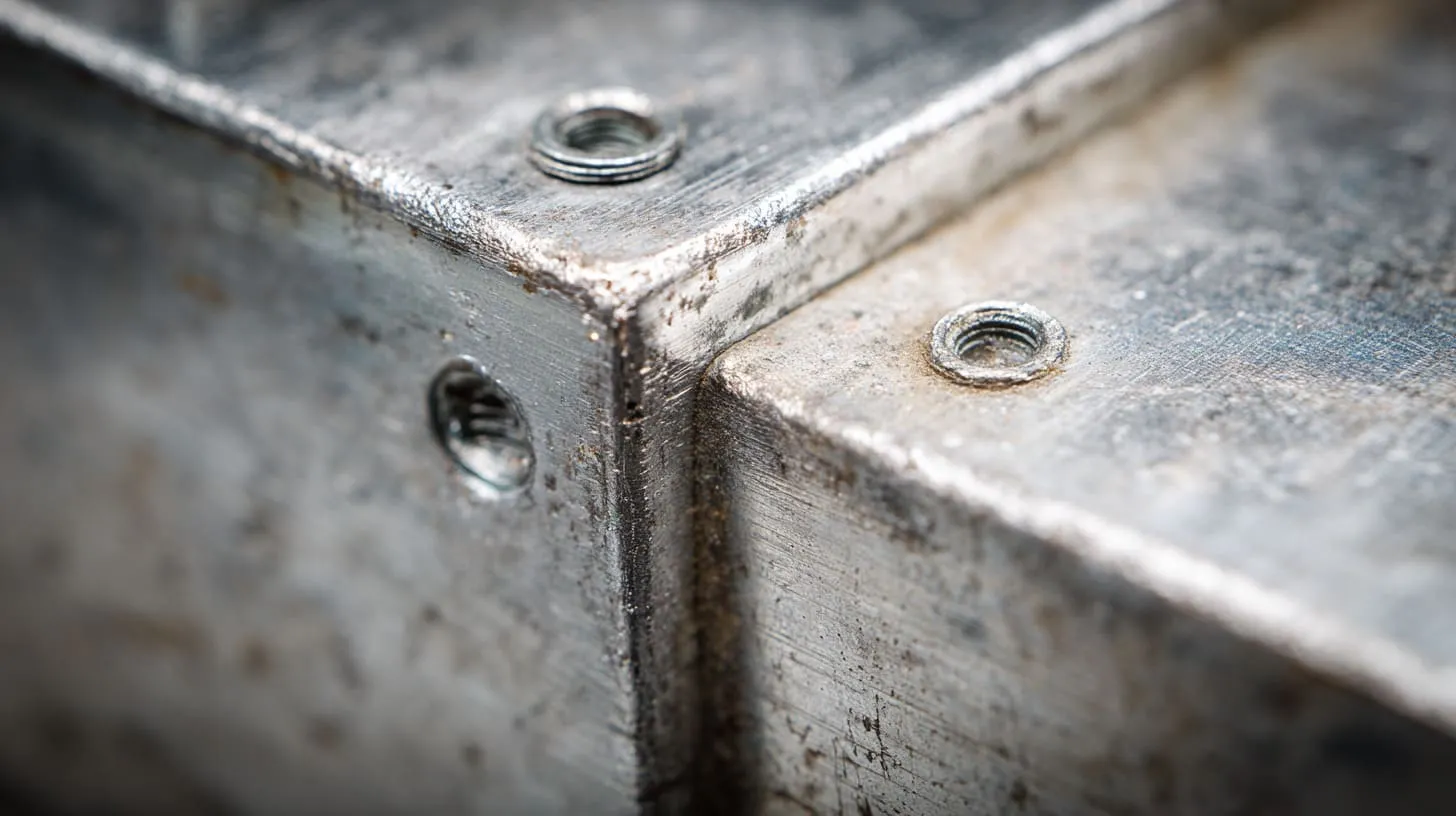
The trouble starts when people confuse possible contact with reliable contact.
A metal lid may touch a metal base. That does not mean the contact is stable enough for EMI shielding over time. It does not mean the contact stays low in resistance after shipping. It does not mean the joint behaves the same in dry air, wet air, vibration, or repeated maintenance.
One thing I watch very closely is whether the contact depends on luck more than control, because luck is a terrible design method.
Oxidation and surface contamination
Aluminum creates oxide naturally. That is not a strange defect. That is normal behavior. The problem is that the oxide layer is not a good conductor in the way many people hope the raw metal surface will be.
Then real life adds more trouble. Oil from handling. Dust from machining. Residue from packaging. Moisture from storage. Corrosion from the environment. None of this looks dramatic at first. That is why it is dangerous.
I once looked at a sample enclosure that seemed fine on first inspection. The fit looked tight. The screws were in place. The parts were machined well. But the interface had light contamination and slight oxidation, and the contact was far less dependable than the drawing suggested. The enclosure did not fail because of one big design disaster. It failed because a small contact assumption met real factory conditions.
Here is a practical breakdown:
| Surface issue | What it does | EMI risk |
|---|---|---|
| Natural aluminum oxide | Raises interface resistance | Reduces continuity quality |
| Finger oils | Create surface film | Makes contact less predictable |
| Dust and debris | Prevent full touch area | Creates local discontinuities |
| Corrosion spots | Damage long-term connection | Causes unstable shielding performance |
Many teams talk about conductivity as if it lives inside the bulk material only. It does not. At seams, the surface condition often decides everything.
Inconsistent contact pressure across surfaces
This problem is easy to underestimate.
Two parts can look like they touch across a wide area, but the actual pressure may exist only in a few places. One screw pulls harder. One flange bends slightly. One panel warps. One tolerance stacks against another. Suddenly the “full contact” design becomes spot contact.
That matters because EMI shielding hates inconsistency.
A seam with strong pressure near fasteners and weak pressure between them may pass one check and fail another. It may behave differently from unit to unit. That kind of variation is terrible for production confidence.
| Pressure issue | What causes it | What happens |
|---|---|---|
| Uneven screw torque | Manual assembly variation | Contact differs by unit |
| Panel flatness variation | Machining or forming limits | Gaps appear across seam |
| Long seam without support | Structural flex | Pressure drops in the middle |
| Tolerance stack-up | Normal part variation | Repeatability suffers |
I pay a lot of attention to the middle of long seams. That is where overconfidence often hides. The ends may look excellent. The center may be telling a very different story.
Mechanical wear and long-term degradation
A contact that works once is not the same as a contact that survives life.
That sounds obvious, but it gets ignored all the time.
Many enclosures are opened and closed more than people expect. Service teams remove panels. Installers retighten screws. End users handle parts roughly. Vibration works on fasteners. Repeated contact rubs the interface. Over time, surfaces change.
I have seen lids that started with acceptable contact and lost that benefit after repeated maintenance. The metal did not disappear. The contact quality did.
This is the kind of degradation I watch for:
- Fretting wear from vibration
- Looser fasteners over time
- Scratched or damaged contact areas
- Surface roughness changing after repeated assembly
- Local corrosion at stressed points
| Lifecycle factor | Short-term view | Long-term reality |
|---|---|---|
| First assembly | Contact seems solid | Performance may drift |
| Repeated opening | Still mechanically usable | Electrical quality may drop |
| Vibrating service environment | Looks minor at first | Joint reliability weakens |
| Field exposure | No immediate visible issue | Contact degrades slowly |
People often ask me whether a direct contact design can work. My answer is usually yes, for a while, under the right conditions, if the details stay controlled. That is a very different answer from saying it is the best choice.
And once surface finish enters the picture, the risk gets even more serious.
The Hidden Risk of Anodized and Coated Surfaces
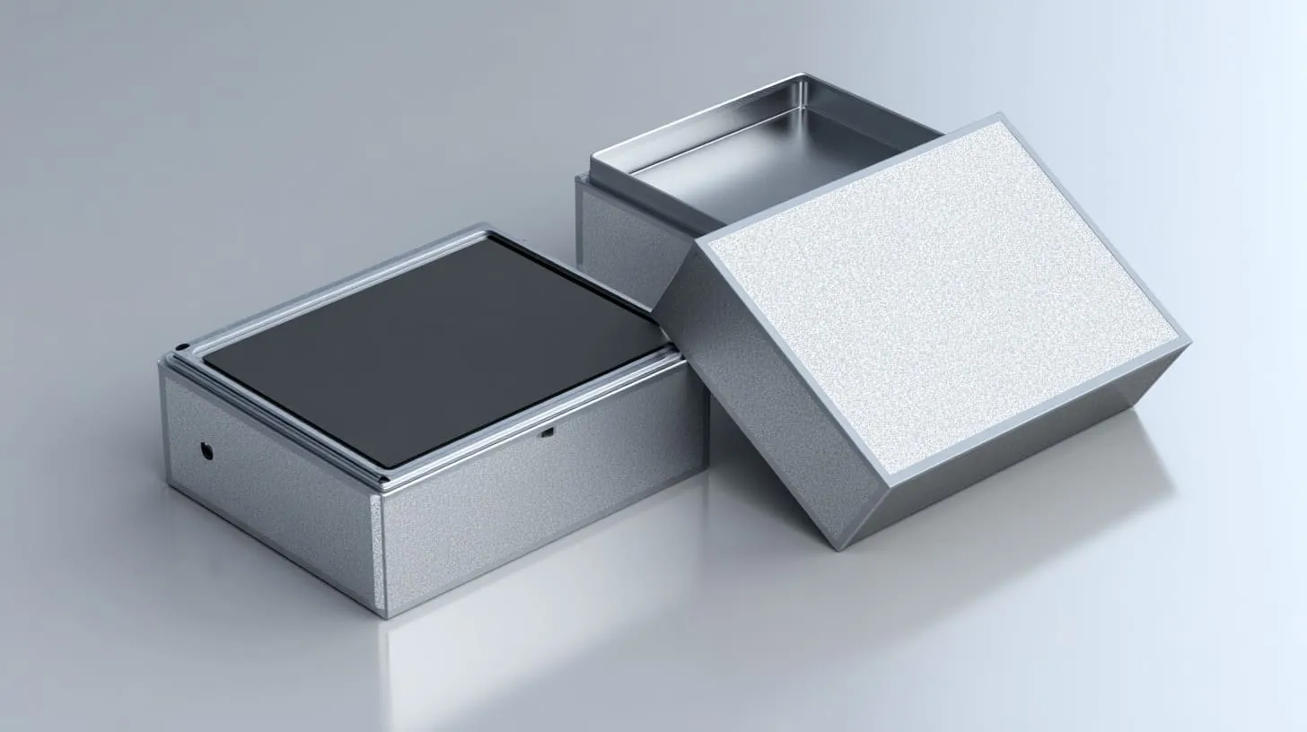
This is where good-looking enclosures can fool people.
A coated metal surface still looks like metal. That visual impression is powerful. It pushes teams into false confidence. They see aluminum. They assume conductivity. They assume shielding continuity. But anodizing, powder coating, and paint do not care about visual expectations.
When a customer asks for a premium surface, I do not argue with the request, but I immediately check whether the finish is about to destroy the electrical path they think they still have.
Why anodized aluminum breaks conductivity
Anodizing is useful. I like it for many applications. It improves corrosion resistance. It improves surface appearance. It gives the product a more refined feel. Buyers often prefer it because it looks finished and durable.
But anodizing also creates an oxide layer. Electrically, that changes the conversation.
The surface still looks metallic. The enclosure still feels solid. Yet the anodized layer can act like an insulator at the very interface where people expect current to flow.
That is why anodized mating surfaces cause so many misunderstandings.
| Surface type | Appearance | Electrical behavior at contact area |
|---|---|---|
| Bare aluminum | Plain metal | Can conduct, but still affected by oxide and contamination |
| Anodized aluminum | Premium metal look | Surface layer can block conduction |
| Masked anodized contact zone | Mixed appearance | Conductive path possible where masking is controlled |
I have had conversations where a team proudly showed me a beautiful anodized enclosure and said the EMI concern was solved because the whole case was metal. That is the kind of statement that sounds strong until someone asks where the actual conductive path crosses the seam.
Powder coating and paint issues
Powder coating and paint create a similar trap, but in a more obvious way if people bother to look closely.
These finishes can completely prevent direct conductive contact unless specific areas are masked, scraped, or designed for alternate grounding paths. Yet many drawings focus on color, texture, and cosmetic coverage first. The shielding path is treated like a later detail.
That later detail becomes a late problem.
I have noticed that some teams choose full coating because it makes quality inspection easier from a cosmetic point of view. The part looks uniform. The finish looks complete. The enclosure looks premium. But if the contact points are not intentionally reserved, then EMI performance is being left to accident or post-process rework.
| Coating condition | Cosmetic result | EMI effect |
|---|---|---|
| Full powder coating on mating surfaces | Clean visual finish | Blocks direct electrical contact |
| Painted seam surfaces | Attractive and protected | Interrupts shielding path |
| Masked contact pads only | Less uniform appearance | Better controlled conductivity |
| Random scraping after coating | Improvised fix | Poor repeatability |
A lot of people dislike visible masking zones because they disturb the clean look. I understand that reaction. But I would rather explain a small cosmetic compromise than explain a failed EMC result after production has started.
Common mistakes in surface treatment decisions
Most of the mistakes here are not technical mysteries. They are decision mistakes.
Teams often:
- Approve coatings before defining grounding strategy
- Assume screws alone will break through the finish well enough
- Forget to specify masked contact areas in the drawing
- Treat EMI performance and cosmetic finish as separate topics
- Let prototype handwork hide a production weakness
This last point matters more than people think. A prototype may pass because somebody lightly scraped an area, tightened screws with extra care, or assembled parts in a cleaner environment than production will ever have. That creates false comfort.
| Mistake | Why it happens | What it causes |
|---|---|---|
| Finish selected first | Cosmetic pressure | Conductive path ignored |
| No masked zone defined | Drawing incomplete | Assembly depends on chance |
| Too much trust in screw bite | Fastener feels strong | Poor seam continuity |
| Prototype hand correction | Sample urgency | Production mismatch later |
This is also the place where engineering becomes more honest. A good-looking part is not always a good electrical part. The sooner a team accepts that, the less pain they create later.
But even bare contact can become unstable when assembly itself introduces variation. That is where the next issue shows up.
When Direct Contact Creates Unstable EMI Performance
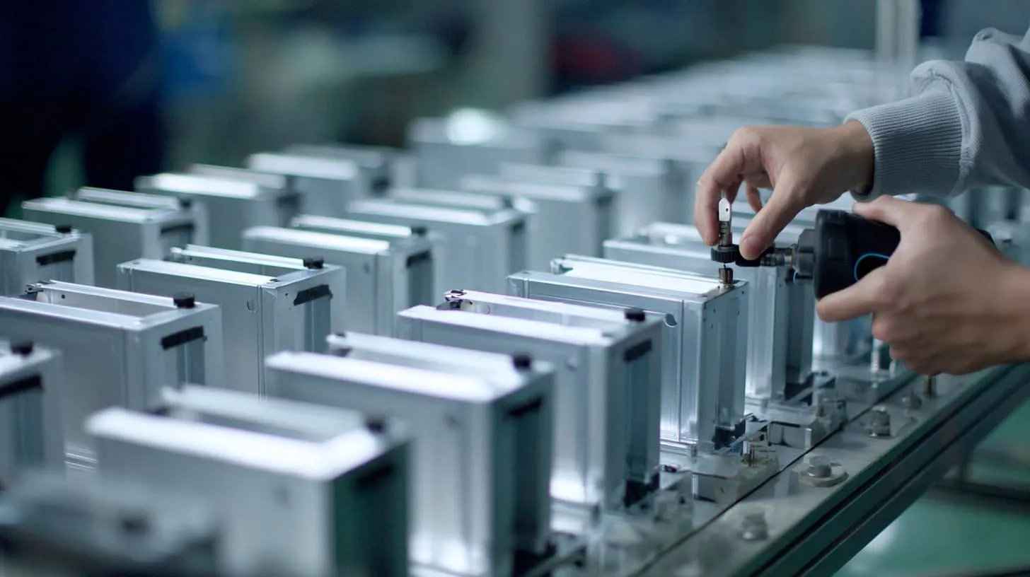
Some shielding solutions fail not because they are fully wrong, but because they are too sensitive.
That is a serious weakness in production work. A design that depends on perfect torque, perfect flatness, perfect cleanliness, and perfect handling is not really a robust design. It is a fragile agreement with ideal conditions.
If a shielding method changes its behavior every time the assembly line changes hands, I treat that as a warning sign, even before test data confirms it.
Sensitivity to assembly variation
Assembly variation is normal. That is the first truth.
One worker tightens screws in a different order. Another uses slightly different torque. A third handles the parts with more speed. One batch of panels has tiny flatness variation. None of this sounds dramatic. Put together, it becomes dramatic enough.
Direct contact solutions often react strongly to those small differences. One unit performs well. Another unit, built from the same drawing, does not.
That creates a painful question for the team: is the design good, or was the last pass just lucky?
| Assembly factor | Small change | Big effect |
|---|---|---|
| Screw torque | Slightly higher or lower | Contact pressure changes |
| Tightening sequence | Different order | Panel seating changes |
| Surface cleanliness | Minor residue | Interface resistance shifts |
| Part flatness | Tiny deviation | Seam contact becomes uneven |
I have learned to fear solutions that require “careful assembly” but do not define what careful means in measurable terms. That kind of language sounds professional and solves almost nothing.
Environmental factors: humidity, temperature, corrosion
The environment keeps negotiating with your design long after the drawing is released.
Humidity can support corrosion. Temperature changes can expand and contract parts. Outdoor conditions can attack exposed contact points. Salt can make things much worse. A contact design that works in a controlled indoor lab can behave very differently in a transport cabinet, outdoor box, or factory environment.
This is why I always ask where the enclosure will live, not just how the enclosure will be made.
| Environmental factor | What changes | Why it matters |
|---|---|---|
| Humidity | Surface condition worsens | Contact resistance may increase |
| Temperature cycling | Parts expand and contract | Pressure can shift across seam |
| Salt exposure | Corrosion speeds up | Conductive quality drops faster |
| Chemical exposure | Surface attack possible | Contact stability falls |
Some buyers focus almost only on initial EMC performance. I understand the pressure. The test deadline is real. But a pass at the beginning is not the whole story. If the enclosure will live a hard life, then the long-term contact story matters just as much.
Field failures vs lab test success
This is one of the most frustrating parts of enclosure work.
A product passes in the lab. Everyone relaxes. Tooling moves forward. Packaging gets approved. Then field complaints start. Maybe not immediately. Maybe after shipping, maintenance, vibration, weather, or repeated use. Suddenly the confidence built around the test result starts to crack.
I do not treat a clean lab result as the final truth if the shielding depends on a contact method that is known to drift in real use.
Here is the comparison that matters:
| Scenario | Lab condition | Field condition |
|---|---|---|
| Assembly | Careful, controlled | Faster, more variable |
| Environment | Clean, stable | Humid, hot, cold, dirty |
| Handling | Minimal | Repeated service and transport |
| Contact condition | Fresh | Aged, worn, contaminated |
That is why I push teams to think beyond “did it pass?” and ask “will it keep passing in the real world we actually sell into?”
Once that question becomes serious, there are some situations where I stop trusting direct contact almost entirely.
Situations Where Metal-to-Metal Contact Should Be Avoided

I do not believe in absolute rules for engineering. Still, there are environments where I become very cautious about using bare metal-to-metal contact as the main EMI strategy.
These are not rare situations either. Many industrial and commercial products live in exactly these conditions.
The moment a project includes movement, weather, corrosion, or too many uncontrolled interfaces, I stop treating direct contact as the default safe choice.
High-vibration environments
Vibration is hard on contact points.
Fasteners shift. Micro-movement happens. Fretting shows up. Pressure changes over time. A contact method that looked fine at the bench may turn unreliable after transport or long operation near motors, fans, compressors, or moving equipment.
Automotive-style conditions, industrial machinery, rail systems, and mobile equipment all bring this risk.
| Vibration condition | What I worry about | Why direct contact struggles |
|---|---|---|
| Continuous machine vibration | Fretting at contact surfaces | Surface quality degrades |
| Transport shock | Fastener movement | Seam pressure changes |
| Fan or motor resonance | Repeated micro-motion | Contact becomes inconsistent |
I have seen teams save a small amount of BOM cost by skipping gasket solutions in a vibration-heavy design. Later, they spent much more time solving instability that was built into the first decision.
Outdoor or harsh environments
Outdoor use changes everything.
Moisture, salt spray, dust, chemicals, and temperature cycling are not friendly to exposed contact assumptions. Even indoor industrial sites can act like harsh environments if they include cleaning chemicals, process dust, or humidity swings.
In those cases, raw contact is often too exposed and too fragile.
| Harsh condition | Risk to contact area | Better mindset |
|---|---|---|
| Outdoor moisture | Corrosion and residue | Use controlled sealed interface |
| Salt air | Rapid contact degradation | Avoid exposed bare paths |
| Chemical exposure | Surface attack | Choose protected conductive method |
| Dust-heavy site | Debris in seam | Design for tolerance and contamination |
I do not like betting long-term shielding on a contact surface that the environment gets to slowly edit for free.
Complex assemblies with multiple mating surfaces
Complex assemblies create another kind of danger: too many variables.
A simple two-part enclosure is one thing. A multi-panel system with doors, removable covers, internal partitions, and many mating lines is something else. Every extra contact surface adds another chance for inconsistency, coating conflict, tolerance stack, and assembly error.
At some point, “metal-to-metal everywhere” stops being a smart strategy and starts being a vague hope.
| Assembly type | Contact challenge | Result |
|---|---|---|
| Two-part box | Limited variables | Easier to control |
| Multi-panel enclosure | Many interfaces | Harder to validate fully |
| Serviceable door design | Repeated opening | Contact drifts over time |
| Modular product family | Variation across models | Repeatability becomes harder |
The more seams I see, the less interested I become in trusting uncontrolled direct contact as the whole answer.
And that naturally leads to the better question: what should we use instead?
Better Alternatives to Direct Metal Contact for EMI Shielding
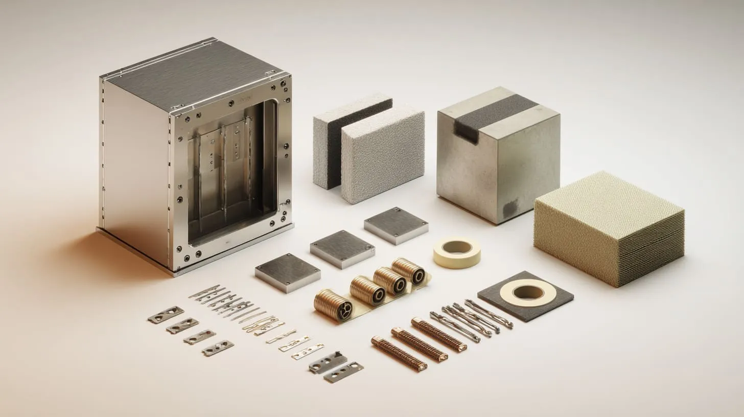
I like alternatives not because they are fancy, but because they are more controllable.
That is the heart of it.
A good shielding solution should not depend too much on luck, surface accident, or heroic assembly discipline. It should create stable electrical behavior in a way that production can repeat. That is why I often prefer designed contact systems over raw contact assumptions.
When I choose an alternative, I am usually not buying more material; I am buying more predictability.
Conductive gaskets and EMI foam
Conductive gaskets and EMI foam help by creating repeatable pressure across a seam. That matters a lot when the metal parts themselves are not perfectly flat or when assembly variation is unavoidable.
They also help bridge small irregularities that raw metal contact does not handle well.
| Option | Strength | Best use case |
|---|---|---|
| Conductive fabric-over-foam gasket | Good compression and seam coverage | Removable lids and doors |
| Conductive elastomer gasket | Sealing plus conductivity | Harsh or sealed environments |
| EMI foam strip | Tolerance compensation | Light enclosures with variable gaps |
I like these options because they admit a simple truth: real parts are not perfect, and real seams need help.
Conductive coatings and plating
Sometimes the best answer is not bare metal at all. It is controlled conductivity through a finish system designed for EMI performance.
Nickel plating, copper plating, and conductive paints can create electrical paths where cosmetic or corrosion demands make raw contact less practical. The exact choice depends on cost, environment, substrate, and the needed shielding level.
| Conductive finish | Main benefit | Typical caution |
|---|---|---|
| Nickel plating | Durable conductive surface | Cost and process control |
| Copper plating | High conductivity | Corrosion and finish protection |
| Conductive paint | Useful on non-metal parts too | Uniformity and wear resistance |
This is especially useful when appearance and performance both matter. Instead of pretending those two needs do not conflict, these methods try to manage the conflict more honestly.
Shielding tapes and spring fingers
These are small parts with a very practical purpose.
Spring fingers are excellent when parts need repeated opening and closing. They maintain contact through mechanical force. Shielding tapes can help on selected paths where redesigning the whole interface is not realistic.
| Alternative | Why I use it | Where it helps |
|---|---|---|
| Spring fingers | Consistent pressure at key points | Service doors and removable covers |
| Conductive tape | Fast fix or selective reinforcement | Prototype tuning or targeted areas |
| Fingerstock contact strips | Durable repeatable contact | Doors, lids, sliding interfaces |
I do not believe every product needs these parts. But I do believe many products would be safer with them than with raw hope disguised as bare metal contact.
Once a team accepts that, the design process itself becomes smarter.
Design Strategies for Reliable EMI Shielding Without Direct Contact
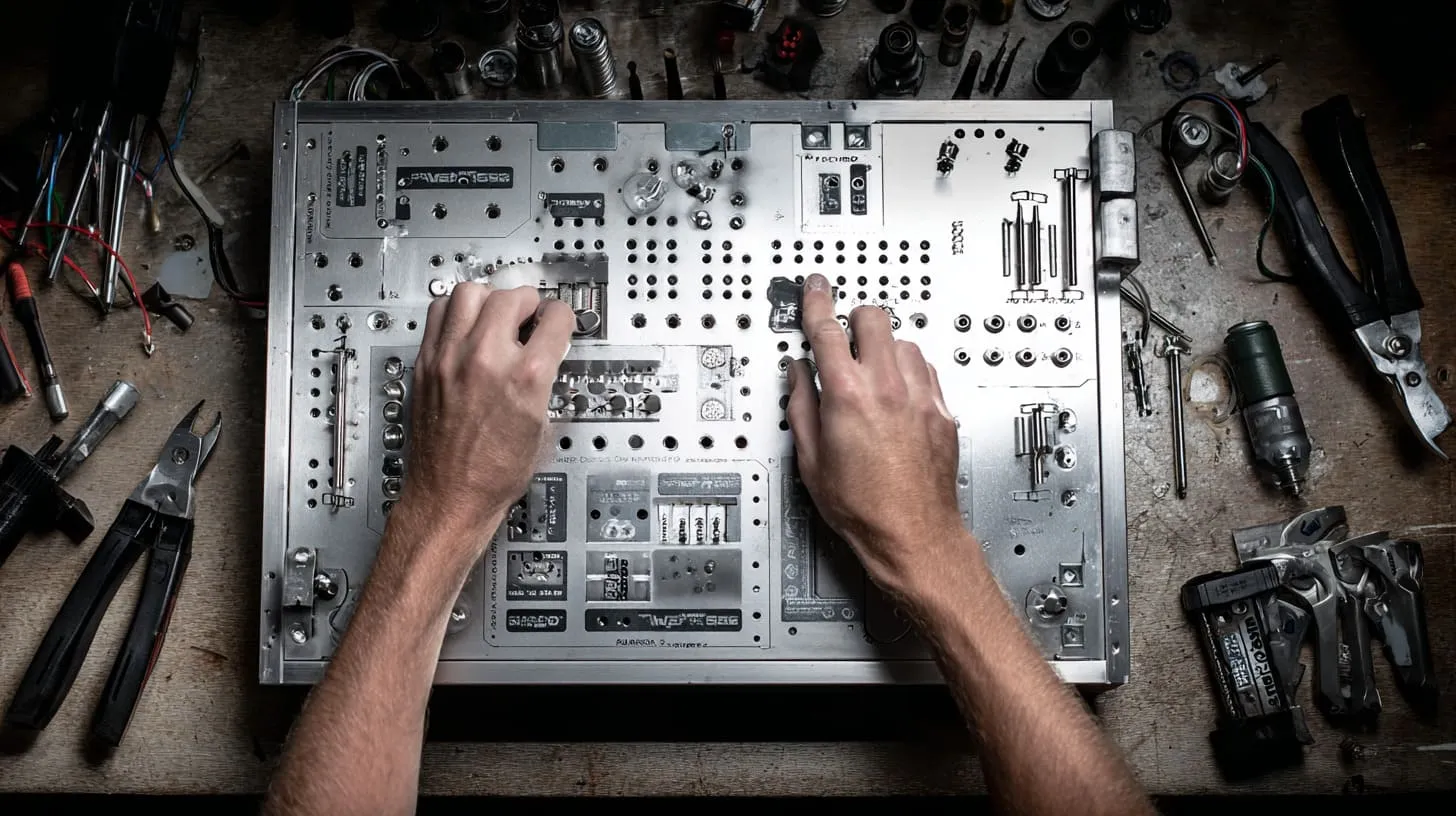
The real goal is not to avoid metal contact at all costs. The goal is to stop depending on uncontrolled contact as the main plan.
That shift changes how I think about enclosure design from the start. Instead of asking, “Will these two parts touch?” I ask, “Where is the intended electrical path, how stable is it, and how repeatable is it in production?”
If a design cannot explain its current path clearly, I assume the product is relying on a coincidence somewhere.
Define controlled grounding paths
A controlled path is far better than a vague one.
I prefer designs that intentionally define where electrical bonding happens. That might mean dedicated grounding points, masked contact pads, bonded fastener zones, conductive gaskets, or planned spring contacts. The point is not to spread contact everywhere. The point is to control it where it matters.
| Design choice | Weak approach | Stronger approach |
|---|---|---|
| Grounding across enclosure | “Parts touch somewhere” | Defined bonding locations |
| Coated seam treatment | Hope screw bites through | Masked or prepared contact area |
| Current path logic | Assumed by layout | Shown in design intent |
That makes troubleshooting easier too. If the intended path is clear, then failure analysis becomes much less chaotic.
Combine mechanical and electrical design thinking
This is where many projects split too early.
Mechanical teams focus on fit, form, and finish. Electrical teams focus on EMC results. Both are correct in their own space. The problem begins when those spaces do not meet early enough.
A seam is both a mechanical feature and an electrical feature. A coating is both a cosmetic choice and an EMI decision. A fastener pattern is both a structural and shielding issue.
| Design topic | Mechanical lens | Electrical lens |
|---|---|---|
| Seam geometry | Flatness and fit | Leakage and continuity |
| Surface finish | Appearance and corrosion | Conductivity risk |
| Screw layout | Retention and assembly | Contact spacing and pressure |
| Door design | Access and usability | Repeatable shielding contact |
I have found that the worst EMI surprises usually grow in the gap between departments, not inside one department alone.
Design for repeatability and manufacturability
Repeatability matters more than elegance.
A clever contact idea that works only under careful manual assembly is weaker than a slightly less elegant design that every factory shift can build the same way. I say this because production always tests the honesty of design.
| Repeatability question | Why I ask it |
|---|---|
| Can this contact survive normal torque variation? | Assembly is never perfectly identical |
| Can the seam work with normal flatness tolerance? | Real parts vary |
| Can the interface survive service opening? | Products live beyond first build |
| Can QC verify the important contact features? | Invisible assumptions are dangerous |
This is where I often slow the project down for one more review. Not because I enjoy delay, but because one extra design argument is cheaper than a late EMC surprise.
And then there is the cost question, which pulls many teams back toward the “simple” raw contact choice.
Cost vs Reliability: Rethinking the “Simplest” Solution
I understand the attraction of direct metal contact from a cost angle.
It looks cheap on paper. No gasket. No plated spring part. No extra conductive component. The BOM stays lean. The assembly looks straightforward. Procurement feels relieved.
But paper cost and project cost are not the same thing.
When the quoted savings come from removing the only feature that controlled shielding stability, I stop calling it savings and start calling it borrowed trouble.
Why metal contact seems cheaper at first
The appeal is easy to explain.
- Fewer parts
- Lower direct material cost
- Less visible assembly complexity
- Faster early decision-making
- Cleaner-looking structure on drawings
| Cost view | Why it looks good |
|---|---|
| BOM cost | No extra EMI hardware |
| Assembly step count | Fewer obvious parts to install |
| Visual simplicity | Clean design story for meetings |
This is why the idea keeps coming back. It is easy to defend at the start.
Hidden costs of failure and redesign
The hidden costs are the part people like least, because they arrive late and hurt more.
A failed EMC test costs time. Rework costs time. Added masking steps cost time. New tooling changes cost money. Field failures cost trust. Delayed shipments damage project rhythm. For B2B buyers, that rhythm matters a lot. One missed launch or delayed batch can undo the value of the early savings.
| Failure cost | What it affects |
|---|---|
| EMC retest | Time and lab budget |
| Drawing revision | Engineering workload |
| Process correction | Factory speed |
| Shipment delay | Customer confidence |
| Field issue | Brand reputation |
I have watched teams save a few dollars on contact strategy and then spend weeks recovering from the side effects. That math never impresses me.
When investing in alternatives makes more sense
Some products can tolerate more risk. Some cannot.
If the product is high value, regulated, service-heavy, outdoor, vibration-prone, or built for long life, then more controlled shielding methods usually make sense much earlier. Even mid-range products can benefit if production volume is high enough that small instability turns into a repeating quality problem.
| Product situation | My usual thinking |
|---|---|
| Low-risk indoor device | Direct contact may be acceptable if tightly controlled |
| Industrial or mobile equipment | I prefer controlled conductive interface |
| Harsh environment enclosure | I avoid bare-contact dependence |
| High-volume production | Repeatable solution becomes more valuable |
| Serviceable product | Spring or gasket solutions often win |
I do not choose shielding details by asking only, “What is the cheapest part today?” I ask, “What costs the least once the product has lived a real life?”
That question is the one that usually brings me to my final view on this topic.
Conclusion
I do not reject metal-to-metal contact because it is useless. I reject the lazy version of it.
That is an important difference.
Direct contact can help EMI shielding. I know that. I use that fact when the design supports it, when the surfaces are truly controlled, when the environment is reasonable, and when the assembly method can repeat the result with confidence. But I have also seen too many projects trust bare contact simply because it sounded correct in theory. Theory matters. So does life. The second part is where weak assumptions usually get exposed.
My view comes from work, not from slogans.
I have watched seams look perfect and behave poorly. I have seen anodized parts fool smart people. I have seen “cheap” solutions become expensive after testing, rework, and shipment delay. I have seen controlled conductive parts save a project not because they looked impressive, but because they removed uncertainty.
That is why I think stability matters more than appearance. I think repeatability matters more than neat theory. I think a controlled shielding path is usually better than a wide contact area that nobody can really explain or verify.
If I sound firm about this, it is because I have learned that EMI problems rarely reward optimism. They reward discipline.
So when I look at an enclosure, I do not ask only whether metal touches metal. I ask whether that contact is intentional, durable, measurable, and still trustworthy after coating, torque change, transport, service, and time. If the answer is weak, I do not force myself to love the simpler option.
I choose the option that gives the product a better chance to survive real work.
If you are working on a custom enclosure project and you want a second set of eyes on seam design, coating choices, grounding paths, or EMI risk points, contact me. I like these conversations because they often save much bigger problems later. You can reach me at info@maidatech.com or visit maidatechenclosure.com.