Skip to content
A drawing can look very clean on the screen.
The lines are straight. The dimensions are clear. The tolerance notes look professional. Then I zoom in and see one note repeated across the whole drawing:
±0.05 mm unless otherwise specified.
At that moment, I usually slow down.
Not because tight tolerance is bad. Tight tolerance is very useful when it protects the product function. But if every dimension is treated as critical, the whole enclosure becomes harder to quote, harder to produce, harder to inspect, and often more expensive than it needs to be.
In aluminum enclosure projects, tolerance is not just a number on the drawing. It is a manufacturing decision. It affects PCB mounting, connector alignment, gasket sealing, sliding covers, screw assembly, surface finishing, and even how the product feels in the customer’s hand.
This is why I do not look at tolerance as a simple factory rule. I look at it as a small decision that can quietly change the whole project.
Why Standard Tolerances Matter in Aluminum Enclosure Design
Standard tolerance gives the factory a realistic production window. It tells us how much variation is acceptable without hurting the product.
For a custom aluminum enclosure, this matters because the enclosure is rarely just a box. It may need to hold a PCB. It may need to match an RJ45 connector. It may need to pass an IP rating. It may need to slide together after anodizing. It may need logo engraving or powder coating. Each of these details can be affected by tolerance.
Here is a simple way I explain it to customers:
| Enclosure Area | Why Tolerance Matters | What Can Go Wrong |
|---|---|---|
| PCB standoffs | Controls board position | PCB bends or screws do not align |
| Connector openings | Controls interface fit | RJ45, USB, or SMA does not sit correctly |
| Gasket groove | Controls sealing pressure | Water leakage or gasket damage |
| Sliding cover | Controls assembly feel | Cover becomes too tight or too loose |
| Outer surface | Controls appearance | Usually less critical than functional areas |
A buyer may think, “I want better quality, so I should ask for tighter tolerance everywhere.”
I understand that thinking. It sounds safe. But in real production, it is not always smart.
The Common Mistake: Treating All Dimensions as Equally Critical
Many drawings do not separate functional dimensions from cosmetic dimensions. This is where problems start.
A PCB mounting hole and an outside cover length do not have the same importance. A gasket groove and a simple decorative edge do not need the same tolerance. A connector cutout and a logo position also have different risk levels.
When I review a drawing, I do not ask, “How tight can we make everything?” I ask, “Which dimensions will cause real trouble if they move?”
That question saves time. It also saves money.
For example, if the outside length of an enclosure is 220 mm, maybe ±0.2 mm or ±0.3 mm is enough. But if an internal standoff must match a PCB hole, we may need tighter control. If a sliding cover must move smoothly after anodizing, we need to think about both machining tolerance and coating thickness.
The better method is simple:
- Use standard tolerance for general dimensions.
- Use tighter tolerance for functional interfaces.
- Confirm finished condition after surface treatment.
- Test the assembly before mass production.
What This Guide Will Help Engineers and Buyers Decide
This guide is written for product engineers, OEM buyers, ODM project owners, and enclosure sourcing teams who want a more practical way to think about aluminum enclosure tolerance.
I will not only explain tolerance definitions. I will explain how I usually judge tolerance in real enclosure projects.
You will see how tolerance changes with:
- CNC machining
- Aluminum extrusion
- Sheet metal bending
- Anodizing
- Powder coating
- Gasket sealing
- PCB mounting
- Connector cutouts
- Assembly stack-up
The goal is not to make every dimension perfect.
The real goal is better: make the right dimensions controlled, and leave the non-critical dimensions realistic.
A tolerance note can look small. But once production starts, that small note can decide cost, lead time, and whether the enclosure assembles smoothly.
What Are Standard Manufacturing Tolerances for Aluminum Enclosures?
The word “standard” sounds simple, but it often creates confusion.
Some customers think standard tolerance means low quality. Some suppliers use “standard tolerance” as a loose excuse. Both sides can misunderstand each other if they do not talk clearly.
For me, standard tolerance means this: a normal and realistic production range for a specific manufacturing process.
A CNC-machined aluminum block, an extruded aluminum profile, and a bent sheet metal enclosure do not share the same natural tolerance. They are made in different ways. They move in different ways. They also fail in different ways.
Before I accept a tolerance note, I always compare the number with the process, the material, and the function of that feature, because a good drawing should match how the part will actually be made.
Basic Meaning of Manufacturing Tolerance
Manufacturing tolerance is the allowed difference between the drawing dimension and the finished part.
If a drawing says a hole is 10.00 mm with ±0.10 mm tolerance, the accepted size may be from 9.90 mm to 10.10 mm. That sounds easy. But in an enclosure, tolerance is not only about one hole. It is about how all parts work together.
A custom aluminum enclosure may include:
- Main housing body
- End plates
- Covers
- Screws
- PCB supports
- Gaskets
- Connector cutouts
- Logo area
- Surface coating
Each part has its own variation. When these variations meet during assembly, the product either fits nicely, or it becomes a headache.
Here is a simple example:
| Drawing Feature | Standard Tolerance May Be Enough? | Why |
|---|---|---|
| Overall enclosure length | Usually yes | Small variation rarely affects function |
| Logo position | Usually yes | Visual alignment matters, but not always mechanical |
| PCB mounting hole position | Maybe no | Board alignment may be affected |
| Gasket groove depth | Often no | Sealing pressure depends on it |
| Sliding rail clearance | Often no | Surface finish can change final fit |
Standard tolerance is not about being careless. It is about putting control where control matters.
Standard Tolerance vs Precision Tolerance
Standard tolerance is suitable for normal size control. It is usually enough for general outside dimensions, simple covers, and cosmetic areas.
Precision tolerance is used when the dimension controls function.
For aluminum enclosures, precision tolerance is usually needed in these areas:
| Feature | Why Precision May Be Needed |
|---|---|
| PCB standoff location | Controls board alignment |
| Connector cutout | Controls interface fit |
| Gasket groove | Controls sealing pressure |
| Sliding slot | Controls movement after finishing |
| Threaded hole | Controls screw assembly |
| Mating surface | Controls final assembly gap |
The mistake is to use precision tolerance as a decoration on the drawing.
A tight tolerance note may look professional. But if it does not protect function, it only adds cost.
I have seen projects where the customer requested tight tolerance on every outer dimension, but the connector cutout clearance was not reviewed. The outer case looked accurate, but the connector did not sit well. That is the wrong place to spend tolerance budget.
Why Aluminum Enclosures Cannot Be Manufactured With Zero Variation
Aluminum is stable, but it is not magic.
Every process creates small changes.
| Source of Variation | Where It Appears |
|---|---|
| Material thickness variation | Sheet metal parts, bent covers |
| Tool wear | CNC holes, pockets, cutouts |
| Machine setup | Hole position, outer profile size |
| Bending springback | Sheet metal angles and flanges |
| Extrusion die behavior | Profile wall thickness and shape |
| Heat from welding | Flatness and corner accuracy |
| Surface finishing | Final size of holes, slots, and mating surfaces |
Even a good factory needs a tolerance window. The goal is not zero variation. The goal is controlled variation.
This is why I often tell customers: “Please do not only send me the tolerance number. Tell me which part of the enclosure cannot fail.”
That conversation is much more useful than arguing about ±0.05 mm or ±0.10 mm in every corner.
Once this basic idea is clear, the next question becomes more practical: which features really need tighter control?
Which Aluminum Enclosure Features Need Tight Tolerances?
Not every dimension deserves the same attention.
I know this sounds simple, but it is one of the most common problems in enclosure drawings. Many drawings are full of dimensions, but they do not tell the factory which dimensions are truly important.
This creates two risks.
First, the supplier may spend too much effort on dimensions that do not matter. Second, the supplier may miss the small feature that can break the whole assembly.
The way I judge this is simple: if a dimension affects PCB fit, connector position, sealing, movement, or assembly feeling, I treat it as a serious dimension; if it only affects general appearance, I check it, but I do not let it control the whole manufacturing strategy.
PCB Mounting Bosses and Standoffs
PCB standoffs look small. But they are often the most important features inside an aluminum enclosure.
If the standoff position is wrong, the PCB may not align with the screw holes. If the standoff height is wrong, the PCB may sit too high or too low. If the board bends after tightening screws, it may create stress on components or connectors.
This is especially important when the PCB has external ports.
For example, if a PCB has a USB-C port on one side and an RJ45 connector on another side, the board position must match the cutouts. The enclosure is not just holding the PCB. It is controlling the user interface.
| PCB Feature | Tolerance Risk | Possible Result |
|---|---|---|
| Standoff position | Hole mismatch | Screws cannot be installed smoothly |
| Standoff height | Board height error | Connector does not align with opening |
| Thread quality | Assembly issue | Screw slips or damages thread |
| Boss diameter | Space conflict | Components may touch the boss |
I usually ask customers for the PCB drawing together with the enclosure drawing. This makes the review much easier.
If I only see the enclosure drawing, I may not know why one hole is important. But when I see the PCB layout, I can understand the real function.
Connector Cutouts and Interface Openings
Connector openings are another high-risk area.
RJ45, USB, HDMI, SMA, power inlets, switches, antennas, displays, and cable glands all need proper clearance. If the opening is too small, the connector may not pass through. If it is too large, the product may look rough. If the position is wrong, the customer may need to force the PCB during assembly.
This is where many enclosure projects fail quietly.
The drawing may look correct. The CNC program may also be correct. But after anodizing or powder coating, the final opening becomes slightly different. Then the connector fit becomes tight.
| Connector Type | Common Tolerance Concern |
|---|---|
| RJ45 | Width and height clearance, board position |
| USB-C | Small opening, sensitive alignment |
| HDMI | Edge clearance and insertion space |
| SMA | Hole diameter and anti-rotation feature |
| Power inlet | Cutout shape and screw hole alignment |
| Display window | Opening size and cosmetic edge quality |
I do not only check the cutout size. I also check the direction of assembly.
Can the connector be inserted after the PCB is installed? Does the cable need finger space? Does the coating reduce the opening? Does the customer expect the connector to sit flush?
These small questions are easy to miss. But they decide whether the enclosure feels well designed.
Gasket Grooves and Sealing Surfaces
Gasket areas are different from normal surfaces.
A gasket needs controlled compression. If the gap is too large, the gasket may not seal. If the gap is too small, the gasket may be over-compressed. Over time, the gasket may lose elasticity or break.
For outdoor enclosures, gasket tolerance is not a cosmetic issue. It is a reliability issue.
| Sealing Area | What Needs Control |
|---|---|
| Gasket groove depth | Compression amount |
| Groove width | Gasket stability |
| Mating surface flatness | Water resistance |
| Screw spacing | Even pressure |
| Surface roughness | Contact quality |
Some buyers only write “IP65” or “IP67” on the drawing. But the rating does not happen by itself. It depends on the gasket, groove, screw pressure, material, and assembly.
If the enclosure needs water resistance, I pay special attention to the sealing path. I want to know where water can collect, where pressure is applied, and where the gasket may move during assembly.
Sliding Covers, End Plates, and Interlocking Parts
Extruded aluminum enclosures often use sliding covers. This is a very common structure for electronics, IoT devices, control modules, and communication products.
The design looks simple. One cover slides into two side rails. End plates close the front and back. But the tolerance is not always simple.
If the clearance is too small, the cover may jam after anodizing. If the clearance is too large, the product may rattle. If the profile has twist, the cover may slide well at one end but feel tight at the other end.
| Sliding Area | Risk |
|---|---|
| Rail width | Cover too tight or loose |
| Cover thickness | Poor sliding feel |
| Anodizing thickness | Reduced clearance |
| Powder coating | Higher jamming risk |
| Profile straightness | Uneven sliding |
For these designs, I prefer to check a finished sample. Raw aluminum can slide well. After surface finishing, the result may change.
This is why I do not like judging sliding fit only from raw parts.
External Dimensions and Cosmetic Surfaces
Outer dimensions still matter. Customers want the enclosure to look neat. They want clean corners, consistent gaps, and stable appearance.
But external dimensions are not always the most critical tolerance area.
If an enclosure is mounted inside another machine, the outer size may be important. If it is a standalone desktop electronics case, the outer size may have more room. If it is a rack-mounted enclosure, width and hole positions become much more serious.
The key is use case.
| External Feature | Usually Critical? | Notes |
|---|---|---|
| Overall length | Sometimes | Critical if it fits another system |
| Outside width | Sometimes | Important for panel or rack fit |
| Logo position | Usually moderate | Visual issue, not usually assembly issue |
| Corner radius | Usually moderate | Appearance and touch feeling |
| Surface flatness | Sometimes | Important for sealing or visible panels |
I try not to over-control cosmetic dimensions unless they affect assembly or customer experience.
A nice-looking enclosure matters. But spending CNC-level tolerance on every outside line is usually not the best way to get quality.
The next part is where tolerance becomes more connected to the actual process. CNC machining is often the first process buyers think about when they want accuracy.
How CNC Machining Tolerances Affect Aluminum Enclosure Design
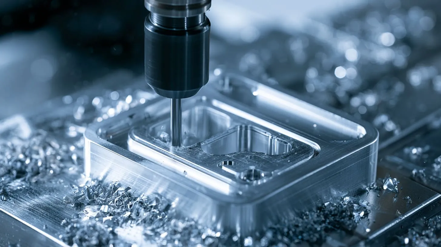
CNC machining gives very good accuracy compared with many other enclosure processes. This is why many customers feel safe when they hear “CNC aluminum enclosure.”
But CNC is not a free pass to ignore design details.
A CNC machine can be accurate, but the part still has material stress, tool limits, clamping limits, wall thickness issues, and finishing changes. A good CNC part starts with a good design.
For CNC enclosure parts, I usually check whether the tight tolerance is fighting the design itself, because sometimes the machine is not the problem; the thin wall, deep pocket, or poor datum choice is the real problem.
Typical CNC Tolerance Expectations
CNC machining is a good choice for:
- Precise holes
- Accurate cutouts
- Milled pockets
- Strong solid-body enclosures
- Heat sink structures
- Complex custom shapes
- Small to medium batch custom projects
For most enclosure cutouts and mounting holes, standard CNC tolerance is usually enough. But some areas may need tighter control, especially when they connect with a PCB, connector, gasket, or another mechanical part.
| CNC Feature | Normal Requirement | When to Tighten |
|---|---|---|
| General outer size | Standard tolerance | If it fits another product |
| Connector cutout | Controlled tolerance | If connector clearance is small |
| PCB hole position | Tighter tolerance | If board has fixed connector location |
| Threaded hole | Controlled thread quality | If repeated assembly is needed |
| Milled groove | Tighter control | If used for gasket or sliding fit |
The important point is not “CNC can be accurate.” The important point is where accuracy is useful.
Thin Walls, Deep Pockets, and Tool Deflection
Thin walls are common in aluminum enclosures because customers want lighter weight and lower material cost. But thin walls can also create machining problems.
During CNC machining, a thin wall may vibrate. It may bend slightly under cutting force. If the tool is long and the pocket is deep, tool deflection may also affect accuracy.
This is why a drawing may look easy, but the machining process may not be stable.
| Design Choice | Manufacturing Risk | Better Direction |
|---|---|---|
| Very thin wall | Vibration or deformation | Increase wall thickness |
| Deep narrow pocket | Tool deflection | Widen pocket or reduce depth |
| Sharp internal corner | Small tool required | Add radius |
| Long unsupported wall | Poor flatness | Add ribs or change structure |
| Tight tolerance on weak area | High scrap risk | Review function first |
Sometimes I suggest a small design change before quoting. The customer may feel I am making the project more complicated. But actually, I am trying to make production more stable.
A 0.5 mm increase in wall thickness can sometimes save much more cost than forcing tight tolerance on a weak structure.
Hole Position, Threaded Holes, and Counterbores
Hole position is one of the most important CNC tolerance topics.
A hole is not just a hole. It may hold a PCB. It may align with an end plate. It may accept a screw. It may fix a connector. It may match another part from another supplier.
If the hole is dimensioned from a random outside edge, inspection may become confusing. If the outside edge has its own tolerance, the hole may be correct from one side but wrong from the real assembly point.
This is why datums matter.
| Hole Type | Important Check |
|---|---|
| PCB mounting hole | Position from PCB datum |
| Threaded hole | Thread depth and material thickness |
| Counterbore | Screw head clearance |
| Countersink | Screw angle and surface finish |
| Connector screw hole | Alignment with connector body |
Threaded holes also need enough material around them. If the wall is too thin, the thread may not be strong enough. If the hole is too close to an edge, the part may crack or deform.
For enclosure design, I do not only check whether the thread can be made. I check whether the thread can survive real assembly.
When CNC Is Better Than Extrusion or Sheet Metal
CNC is better when the design needs precision, strength, and complex geometry.
But CNC is not always the best choice.
If the enclosure is a simple rectangular box, sheet metal or extrusion may be more cost-effective. If the quantity is high and the cross-section is stable, extrusion may be better. If the product needs many bends and large panels, sheet metal may make more sense.
| Process | Better For | Not Ideal For |
|---|---|---|
| CNC machining | High precision, complex shape, strong body | Very low-cost simple boxes |
| Aluminum extrusion | Long profiles, heat dissipation, stable cross-section | Complex changing shapes |
| Sheet metal | Large panels, bent boxes, lower tooling cost | Very tight 3D accuracy |
| Die casting | High-volume shaped housings | Low-volume projects with frequent changes |
Some buyers choose CNC because it sounds premium. I prefer to choose CNC when the design really needs it.
A good supplier should not push one process for every project. The right process depends on tolerance, quantity, structure, surface finish, and budget.
CNC gives us strong control, but many aluminum enclosures are not CNC-only. Extrusion brings its own tolerance logic, and it needs a different mindset.
How Aluminum Extrusion Tolerances Affect Enclosure Design
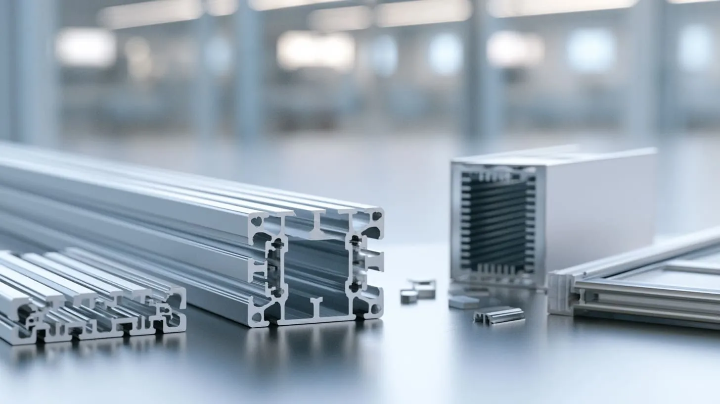
Aluminum extrusion is widely used for electronic enclosures. It is strong, clean, and efficient. It also gives good heat dissipation when the profile includes fins.
But extrusion is not the same as CNC machining.
An extruded profile is pushed through a die. The shape is formed by material flow. This means wall thickness, profile balance, die condition, cooling, cutting, and straightness all affect the final result.
When I review an extruded enclosure, I pay more attention to profile balance and sliding clearance than to one single number on the drawing, because the profile must be manufacturable along the full length, not only accurate at one small point.
Why Extruded Aluminum Profiles Have Natural Variation
An extrusion profile may look simple from the front view. But the factory sees more than the front view.
We see wall thickness. We see hollow areas. We see thin ribs. We see deep slots. We see whether the shape is balanced or difficult to extrude.
The more complex the profile, the harder it is to control.
| Extrusion Factor | Tolerance Impact |
|---|---|
| Profile size | Larger profiles may have more variation |
| Wall thickness | Thin walls are harder to control |
| Shape complexity | Complex sections may distort |
| Die condition | Worn dies affect profile accuracy |
| Cooling | Uneven cooling may cause twist |
| Length | Longer parts may show straightness issues |
This is why I do not expect extrusion to behave like CNC.
A CNC machine cuts material away. Extrusion forms material through a die. These are different worlds.
Wall Thickness and Profile Shape Tolerance
Wall thickness is a big design decision in extrusion.
Thin walls reduce weight and material cost. But if the wall is too thin, the profile may be weak, uneven, or difficult to keep straight. Uneven wall thickness can also make extrusion less stable.
A better extrusion profile often uses balanced wall thickness and smooth transitions.
| Design Choice | Possible Benefit | Possible Risk |
|---|---|---|
| Thin wall | Lower weight and cost | Deformation, weak structure |
| Thick wall | Better strength | Higher material cost |
| Uneven wall | Local strength where needed | Harder extrusion flow |
| Balanced wall | Stable production | May need design adjustment |
| Sharp transition | Saves space | Stress and flow problems |
For heat sink enclosures, fins also need special attention. Very thin fins may look good in a 3D model, but they can be fragile or hard to control in extrusion.
I usually ask: does this wall thickness help the product, or is it only trying to save material? If it saves a little material but creates production risk, it may not be worth it.
Cut Length Tolerance After Extrusion
Extruded profiles are usually produced in long bars and then cut to length.
This cutting step has its own tolerance. The profile may also need CNC machining after cutting, such as connector holes, screw holes, slots, or end plate features.
Length tolerance matters because it affects end plates, cover fit, and final appearance.
| Length-Related Area | Risk |
|---|---|
| Short enclosure | Small variation is easier to control |
| Long enclosure | Straightness and cut accuracy matter more |
| End plate assembly | Length affects front/back fit |
| Sliding cover | Length and rail straightness both matter |
| Cosmetic gap | Uneven cut may show at the end |
For long extruded enclosures, I prefer a realistic tolerance. If the customer needs a very tight final length, we may need secondary machining after cutting.
That adds cost, but it may be necessary for some projects.
Sliding Cover and Rail Clearance
Sliding covers are very common in extruded aluminum enclosures.
They look simple. But they need good clearance planning.
The cover must slide smoothly before and after surface finishing. Anodizing adds a thin layer. Powder coating adds more. If the clearance is too small, the cover may become tight. If the clearance is too large, it may feel loose.
| Condition | Raw Aluminum Fit | Finished Fit |
|---|---|---|
| Tight raw clearance | Feels precise | May jam after coating |
| Loose raw clearance | Slides easily | May rattle after finishing |
| Balanced clearance | Slightly free | Usually best after finishing |
| No coating allowance | Looks fine in drawing | Risk appears after production |
I like to test sliding parts in the final surface finish, not only in raw aluminum. A raw sample can lie to you. It may feel perfect before finishing and fail after anodizing or powder coating.
For ODM projects, I often suggest making one sample with final finishing before confirming the mass production tolerance.
Extrusion is great for long and stable enclosure bodies. But when the design becomes a bent box or a control cabinet, sheet metal tolerance becomes a different story.
How Sheet Metal Tolerances Affect Aluminum Enclosures
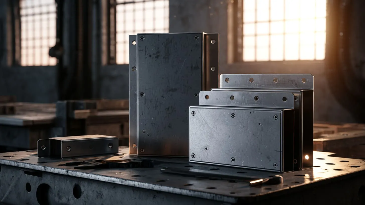
Sheet metal enclosures are practical. They are used for control boxes, rack enclosures, panels, brackets, electrical housings, and many industrial products.
But sheet metal is not a solid block. It is cut, bent, sometimes welded, sometimes ground, and often powder coated. Every step can move the final dimension a little.
For sheet metal aluminum enclosures, I do not judge quality only by one flat drawing dimension; I check the bending sequence, hole location, material choice, and whether the final assembly can tolerate small movement.
Bending Tolerance and Springback
Bending creates variation.
When aluminum sheet is bent, it does not always stay exactly at the angle created by the tooling. It may spring back slightly. The amount depends on material, thickness, bend radius, tooling, and bending direction.
This is why bent parts need realistic tolerance.
| Factor | Effect on Bending |
|---|---|
| Material grade | Affects formability |
| Sheet thickness | Affects bend force and radius |
| Bend radius | Affects cracking risk and size |
| Tooling | Affects angle consistency |
| Grain direction | May affect cracking |
| Part size | Larger parts are harder to control |
For many aluminum sheet metal enclosures, 5052 is often easier to bend than 6061. 6061 is strong, but it is not always friendly for tight bends. If the customer chooses 6061 only because it sounds stronger, I usually ask whether bending is required.
Strength is useful. But formability also matters.
Hole Position After Bending
A hole may be accurate before bending. But after bending, its final position may change.
This is very important for holes near bends. If a hole is too close to a bend line, it may deform. If a cutout crosses a bend area, the shape may change. If the hole must match another part after bending, the tolerance should be reviewed in the formed condition.
| Hole Location | Risk Level |
|---|---|
| Far from bend | Lower risk |
| Near bend line | Higher risk |
| On bent flange | Needs review |
| Large cutout near bend | High risk |
| Hole matched with another part | Critical |
A flat sheet drawing is not the final part. The final part is 3D.
That sounds obvious, but many tolerance problems happen because the flat pattern and formed part are not reviewed together.
If a hole is critical, post-machining after bending may be needed. It costs more, but it may protect assembly.
Flatness, Warping, and Large Panel Control
Large sheet metal panels can warp.
Cutting may release stress. Welding may add heat. Powder coating may also expose the part to heat. If the panel is large and thin, flatness becomes harder to control.
This matters when the enclosure needs:
- Door sealing
- Gasket contact
- Panel mounting
- Display installation
- Tight assembly gaps
- Clean visual appearance
| Panel Type | Common Concern |
|---|---|
| Large front panel | Warping and visible waves |
| Door panel | Gasket sealing and gap control |
| Bottom plate | Mounting stability |
| Thin cover | Flexing and vibration |
| Powder coated panel | Heat-related shape change |
A large panel can meet the general size tolerance but still look bad if it is not flat enough. This is why flatness should be discussed when the surface is large or functional.
Sometimes adding a flange, rib, or thicker material is better than demanding very tight flatness from a weak panel.
Welded Corners and Assembly Tolerance
Welding changes tolerance.
Heat can pull corners. It can create distortion. After welding, grinding and polishing may also change the surface. If the enclosure must look clean and also assemble tightly, welded areas need enough tolerance allowance.
| Welded Feature | Possible Issue |
|---|---|
| Corner weld | Heat distortion |
| Ground surface | Slight geometry change |
| Long seam | Warping |
| Welded bracket | Position shift |
| Sealed box | Flatness and leak risk |
For welded aluminum sheet metal enclosures, the design should allow for production reality.
If the customer needs very tight assembly after welding, we may need fixtures, welding sequence control, and final inspection. In some cases, we may need machining after welding.
That is possible. But it should be planned early.
Sheet metal tolerance is already affected by cutting, bending, and welding. Then surface finishing adds another layer of change. This is where many drawings become too optimistic.
How Surface Finishing Changes Final Tolerances
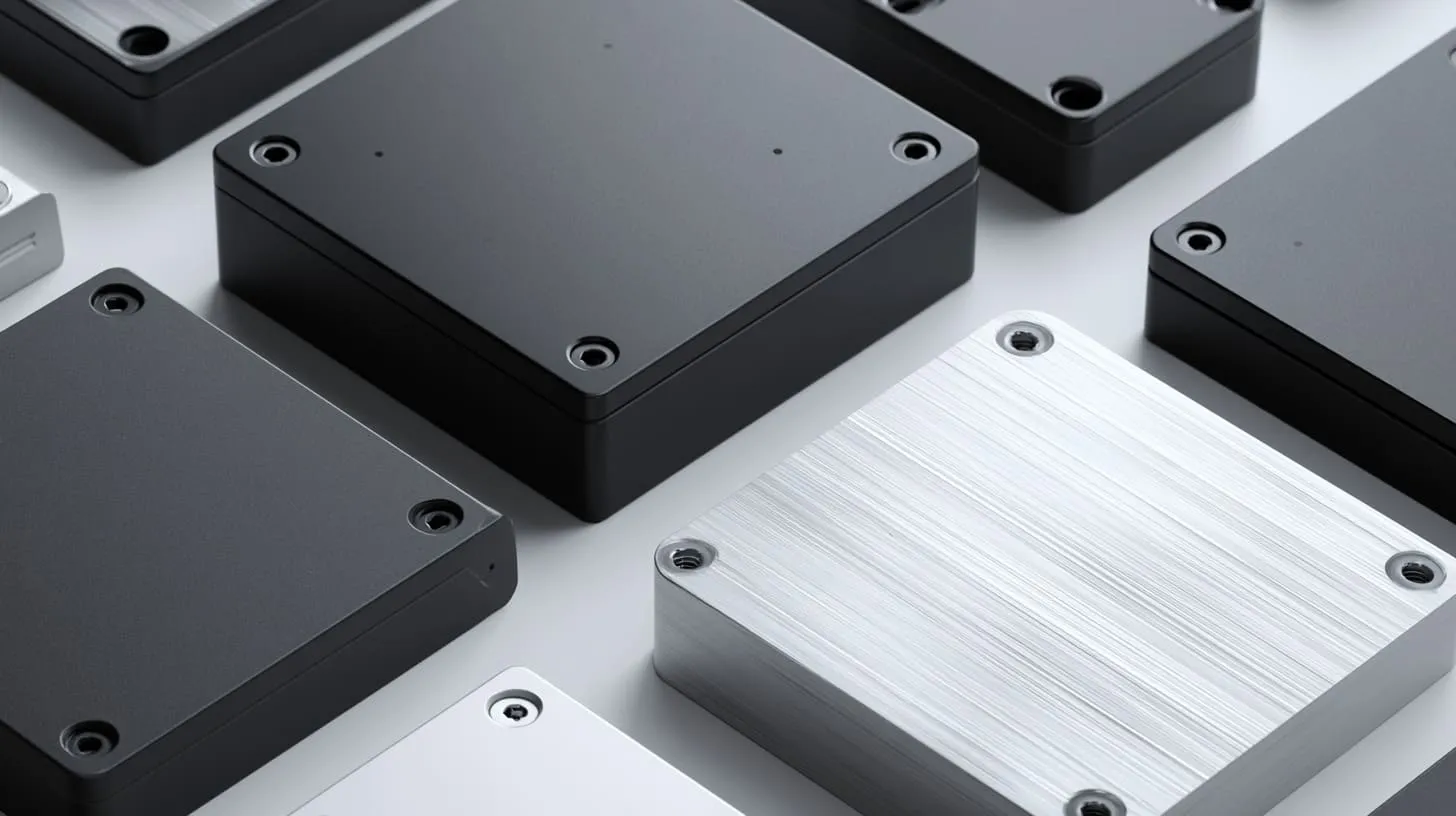
Surface finishing is often treated like the final decoration step.
I do not see it that way.
For aluminum enclosures, anodizing, powder coating, brushing, sandblasting, and masking can all affect the final part. Some changes are small. Some are large enough to cause assembly problems.
When I see tight slots, threaded holes, sliding covers, or gasket areas, I always ask whether the tolerance applies before or after finishing, because a beautiful coating is not helpful if the enclosure no longer fits.
Anodizing Thickness and Dimensional Change
Anodizing creates a protective oxide layer on aluminum. It is widely used for extruded and CNC-machined aluminum enclosures.
The dimensional change is usually smaller than powder coating, but it is not zero.
For many general surfaces, this change is not a problem. But for tight holes, sliding slots, close-fit covers, and threads, it can matter.
| Feature | Anodizing Concern |
|---|---|
| Small holes | Final diameter may reduce |
| Sliding rails | Clearance may become tighter |
| Threaded holes | Thread fit may change |
| Gasket groove | Dimension may shift slightly |
| Cosmetic surface | Color and texture consistency |
This is why the drawing should say whether the dimension is measured before or after anodizing.
If the customer only gives final assembly requirements, I prefer to discuss finished dimensions. If the customer gives machining drawings, we need to decide how to allow for anodizing.
Powder Coating Thickness and Fit Risk
Powder coating usually adds more thickness than anodizing. It is good for protection and appearance, especially for sheet metal enclosures and outdoor products.
But powder coating can create fit problems if the design has no allowance.
Common risk areas include:
- Screw holes
- Connector openings
- Sliding covers
- Grounding points
- Gasket contact surfaces
- Tight assembly gaps
- Labels or logo areas
| Area | Powder Coating Risk | Possible Solution |
|---|---|---|
| Threaded hole | Screw becomes tight | Masking or tapping after coating |
| Sliding rail | Cover jams | Add clearance or mask rail |
| Grounding area | Electrical contact blocked | Mask contact point |
| Connector cutout | Opening becomes smaller | Add coating allowance |
| Gasket surface | Compression changes | Control coating thickness or mask |
Powder coating looks simple in the RFQ. But the real question is: where should coating exist, and where should it not exist?
For electrical enclosures, grounding areas may need masking. For sliding parts, rails may need special control. For connector cutouts, the finished opening must be checked.
Brushing, Sandblasting, and Cosmetic Surface Preparation
Brushing and sandblasting are often used to improve appearance before anodizing or coating.
They can make the enclosure look cleaner. They can reduce small tool marks. They can create a more uniform surface.
But cosmetic finishing is not the same as dimensional control.
| Surface Process | Main Purpose | Tolerance Concern |
|---|---|---|
| Brushing | Linear surface texture | Edge condition may change slightly |
| Sandblasting | Matte surface | Surface texture and appearance control |
| Polishing | Smooth surface | Edge rounding risk |
| Grinding | Remove weld marks | Local geometry may change |
| Deburring | Remove sharp edges | Hole edge and small feature change |
Some buyers ask for perfect surface appearance and tight mechanical accuracy at the same time. That is possible in many cases, but we need to define which surfaces are cosmetic and which surfaces are functional.
A brushed outer cover may only need visual consistency. A gasket surface needs contact control. They should not be treated the same way.
Masking Critical Areas Before Finishing
Masking is one of the simplest ways to avoid many problems.
Critical areas can be protected before anodizing or powder coating. This can help keep threads clean, grounding points conductive, gasket surfaces stable, and sliding areas usable.
| Area to Mask | Reason |
|---|---|
| Threaded holes | Avoid coating buildup |
| Grounding points | Keep metal-to-metal contact |
| Gasket surfaces | Keep sealing control |
| Sliding rails | Prevent jamming |
| Tight connector areas | Maintain final clearance |
Masking should be confirmed before production. It should not be an emergency fix after parts fail.
If masking is needed, the drawing or production note should show the masking area clearly. A short note can prevent long arguments later.
Surface finishing often turns a good raw part into either a better product or a new problem. The next issue is even more hidden: tolerance stack-up.
How Tolerance Stack-Up Causes Assembly Problems
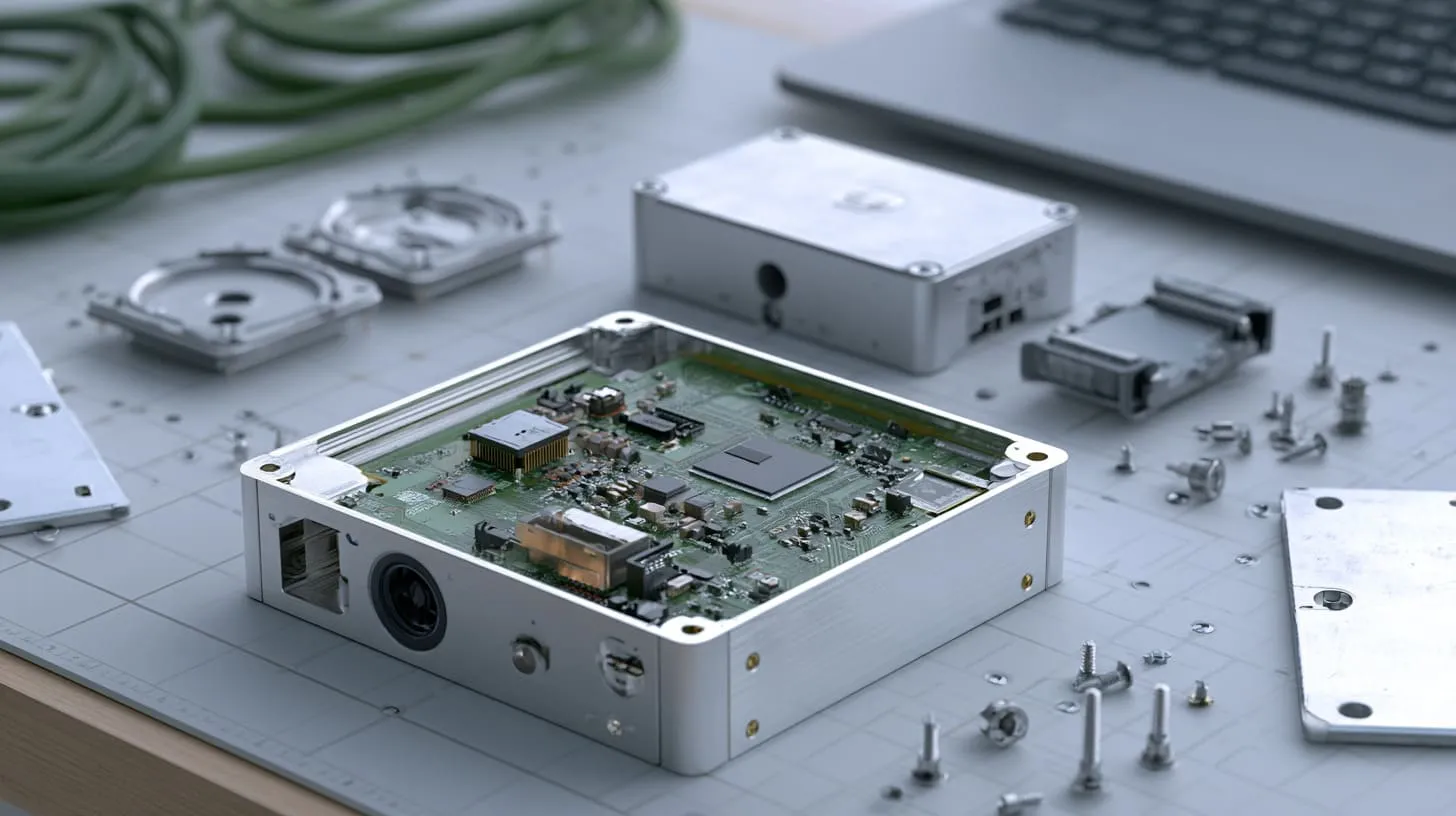
Tolerance stack-up is one of those problems that does not look serious until final assembly.
Each part may pass inspection. The housing may pass. The PCB may pass. The end plate may pass. The gasket may pass. But when all parts come together, something feels wrong.
The screw does not go in smoothly. The connector is slightly off. The gasket is too compressed in one corner. The cover is tight at one end and loose at the other.
That is tolerance stack-up.
The part I watch most closely is not always the tightest tolerance on the drawing; it is the chain of dimensions that meet during assembly, because several small “acceptable” errors can still create one big practical problem.
What Tolerance Stack-Up Means in Enclosure Projects
Tolerance stack-up means that several small variations combine.
For example:
- The PCB hole position has variation.
- The standoff position has variation.
- The connector position on the PCB has variation.
- The enclosure cutout has variation.
- The coating thickness changes the final opening.
Each variation may be acceptable alone. But together, they may create misalignment.
| Part | Small Variation | Final Risk |
|---|---|---|
| PCB | Hole position changes | Board shifts |
| Standoff | Position changes | Screw alignment issue |
| Connector | Location changes | Port does not match cutout |
| Enclosure wall | Machining variation | Opening shifts |
| Coating | Opening gets smaller | Connector clearance problem |
This is why I like reviewing the full assembly, not only one part drawing.
A good enclosure supplier should think like an assembly partner, not only a part maker.
PCB, Connector, and Housing Alignment
PCB alignment is a classic stack-up problem.
A customer may send the enclosure drawing and PCB drawing separately. Each one looks fine. But when we place them together, we may find the connector is too close to the edge, or the opening has no coating allowance, or the board has no room to shift during assembly.
For products like IoT gateways, routers, Raspberry Pi style cases, industrial controllers, and communication devices, this matters a lot.
| Interface | Stack-Up Concern |
|---|---|
| PCB to standoff | Hole alignment |
| PCB connector to housing | Port opening position |
| End plate to housing | Screw and edge fit |
| Antenna connector to wall | Hole position and washer clearance |
| Display to front cover | Window alignment |
Sometimes the solution is not tighter tolerance. The solution may be better clearance.
This is an important point. If the design gives no room for normal variation, the factory must fight the drawing. A little smart clearance can make assembly much more stable.
Gasket Compression and IP Rating Risk
Gasket sealing is also affected by stack-up.
The gasket has thickness tolerance. The groove has machining tolerance. The cover has flatness tolerance. The screw positions affect pressure. The coating may change the contact surface.
If these are not reviewed together, the enclosure may fail water resistance even if each individual part seems acceptable.
| Sealing Factor | What Can Go Wrong |
|---|---|
| Gasket thickness | Too much or too little compression |
| Groove depth | Seal does not sit correctly |
| Cover flatness | Uneven pressure |
| Screw spacing | Local leakage |
| Coating thickness | Gap changes |
For IP-rated enclosures, I do not only ask for the target rating. I want to know the real use condition.
Is it indoor dust? Outdoor rain? Washdown? Coastal air? Temporary immersion? The tolerance strategy changes with the risk.
An IP54 meter box and an IP67 outdoor gateway should not be reviewed with the same mindset.
Screw Assembly and Fastener Clearance
Screw assembly looks simple, but it often reveals tolerance problems.
If screw holes are too tight, assembly becomes slow. If threads are coated, screws may jam. If the holes do not align, workers may force the screw and damage the part.
| Screw Issue | Possible Cause |
|---|---|
| Screw hard to install | Hole too tight or coating buildup |
| Screw angle wrong | Hole position mismatch |
| Thread damage | Weak material or poor tapping |
| Cover gap uneven | Stack-up from multiple parts |
| Assembly slow | Clearance too small |
For mass production, screw assembly speed matters. A design that works once in a prototype may not be good for 1,000 pieces.
That is why I look at repeated assembly, not only first assembly.
After we understand stack-up, the next question becomes very practical: how should the drawing show tolerance clearly?
How to Specify Tolerances on Aluminum Enclosure Drawings
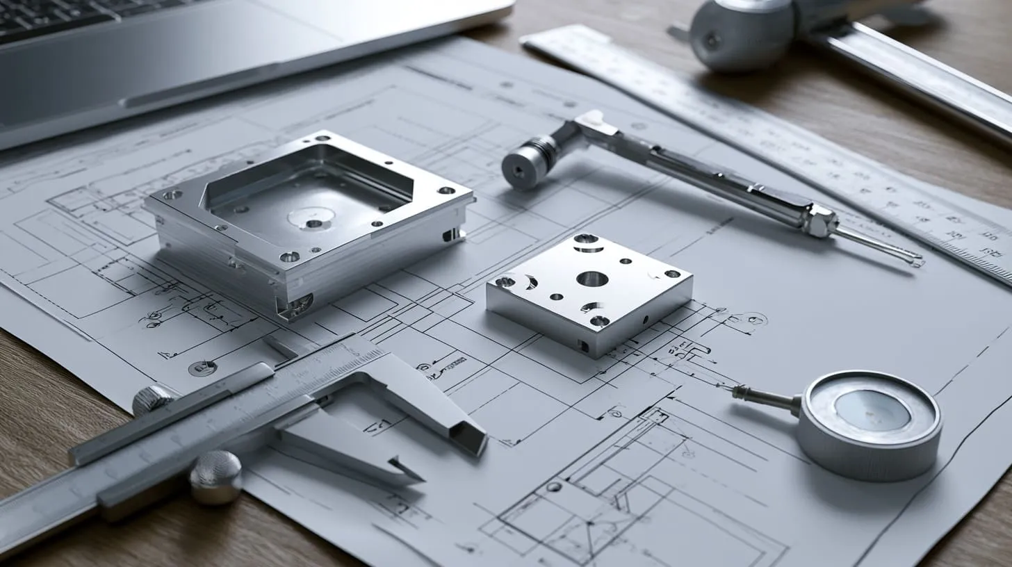
A good drawing does not need to be complicated. But it must be clear.
Many tolerance problems come from unclear drawings, not from bad machines. The supplier reads one meaning. The customer expects another meaning. Then the dispute appears after production.
For custom aluminum enclosures, I like drawings that tell me three things clearly:
- Which dimensions are critical
- Which condition should be inspected
- Which areas need special treatment
A clean drawing helps both sides move faster.
When I prepare feedback for a customer drawing, I try to reduce guessing, because guessing is where quotation mistakes, production delays, and quality arguments usually begin.
Separate Critical and Non-Critical Dimensions
This is the first step.
Not all dimensions should carry the same tolerance. If everything is critical, nothing is really clear.
A better drawing marks key dimensions and allows standard tolerance for the rest.
| Dimension Type | Suggested Treatment |
|---|---|
| PCB mounting holes | Mark as critical |
| Connector cutouts | Mark as critical |
| Gasket groove | Mark as critical |
| Overall outside size | Standard tolerance unless fit-controlled |
| Logo area | Cosmetic control |
| General wall thickness | Process-based tolerance |
This helps the factory focus inspection effort.
It also helps the buyer control cost. The factory does not need to over-machine or over-inspect areas that do not affect performance.
Define Datums for Important Features
Datums are reference points. They tell the factory and inspector where dimensions should start.
If a connector cutout is important, it should be dimensioned from a functional datum. If the PCB position controls the connector location, the hole pattern should be connected to that logic.
Poor datum selection creates confusion.
| Poor Method | Better Method |
|---|---|
| Dimension from random outer edge | Dimension from functional mounting datum |
| Chain many dimensions together | Use common reference points |
| Mix cosmetic and functional references | Separate appearance and assembly logic |
| Leave inspection unclear | Define measurable references |
For example, if an RJ45 opening must match a PCB connector, it may be better to reference the opening from the PCB mounting datum instead of a decorative outer edge.
That small change makes the drawing easier to inspect and easier to produce.
Clarify Raw Part vs Finished Part Dimensions
This is a very common source of trouble.
A drawing may show a 10.00 mm hole. But does that mean before anodizing? After anodizing? Before powder coating? After powder coating?
If the hole is not critical, maybe it does not matter much. But if the hole is for a connector or sliding feature, it matters.
| Drawing Note | Why It Matters |
|---|---|
| Dimensions apply before anodizing | Factory machines raw size and finishes later |
| Dimensions apply after anodizing | Factory must allow for finishing |
| Mask threaded holes | Prevent screw fit problems |
| Mask grounding area | Keep electrical contact |
| Inspect after coating | Protect final assembly |
I prefer to confirm finished-condition requirements for close-fit parts. The customer uses the finished enclosure, not the raw machined part.
Use Notes for Coating, Masking, and Inspection
Short notes can prevent big problems.
A drawing should not only show dimensions. It should also show important process requirements.
Useful notes may include:
- Surface finish type
- Coating color
- Coating thickness range if needed
- Masked areas
- Thread protection
- Inspection condition
- Critical dimensions
- Deburring requirement
- Logo position and method
| Drawing Note | Example Purpose |
|---|---|
| Mask all M3 threaded holes | Avoid coating buildup |
| Keep grounding pad uncoated | Ensure conductivity |
| Inspect connector opening after coating | Protect final fit |
| Deburr all sharp edges | Improve safety and assembly |
| Critical dimensions marked with C | Focus QC work |
These notes are not fancy. They are practical.
In many projects, one clear note saves several rounds of email.
But there is another side to this topic. Some buyers do specify tolerances clearly, but they specify too much.
What Tolerances Should Buyers Avoid Over-Specifying?
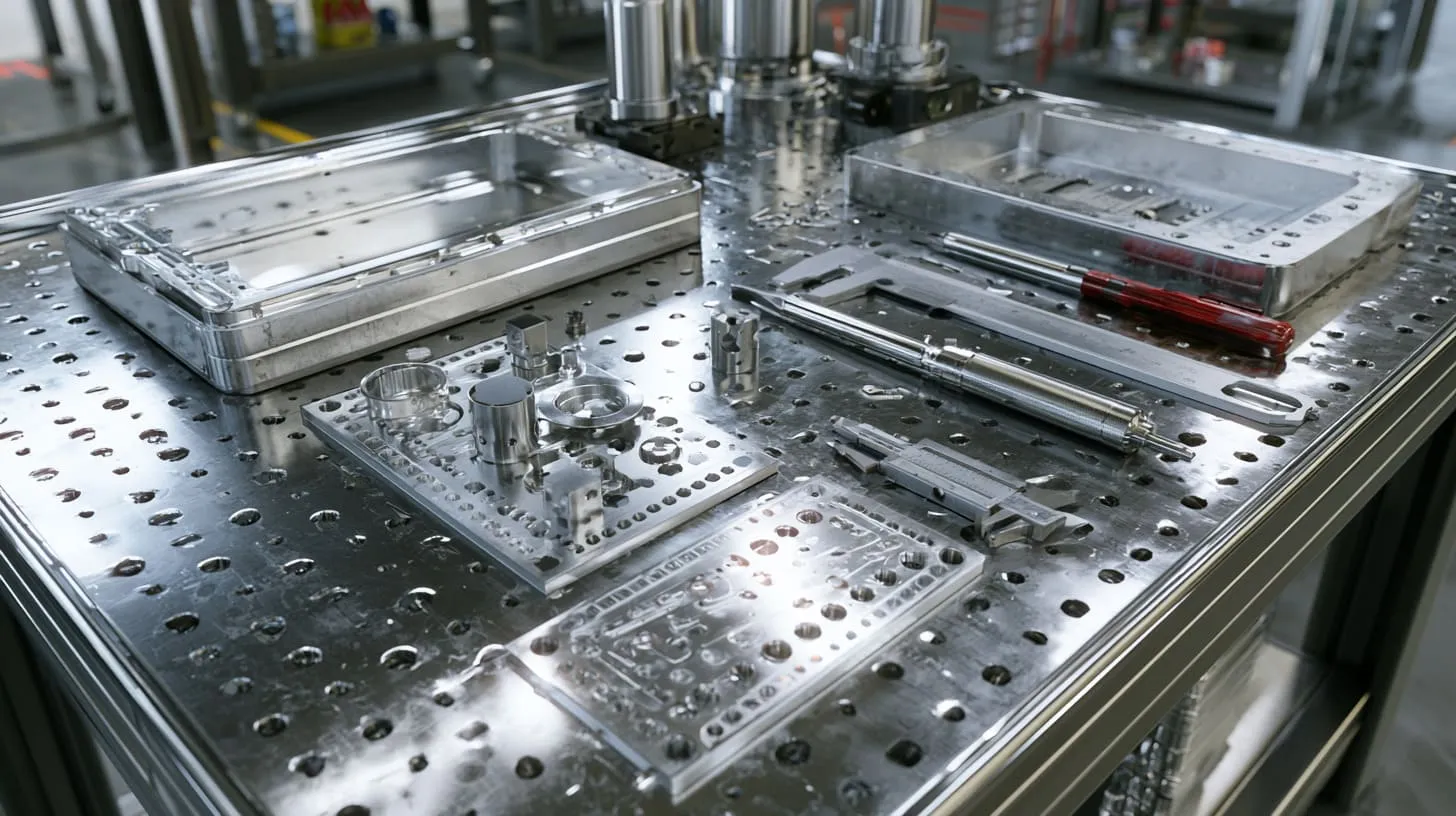
Over-specifying tolerance feels safe.
I understand why buyers do it. They want to avoid mistakes. They want the supplier to take quality seriously. They want parts that fit well.
But very tight tolerance on every dimension can create the opposite result. It can slow quotation, raise cost, increase scrap, and distract attention from the real critical features.
The question I ask is not “Can we make it tighter?” but “Will tighter tolerance improve the product enough to justify the extra cost and risk?”
Avoid Tight Tolerances on Every Dimension
A full drawing with tight tolerance everywhere is hard to produce and hard to inspect.
The factory must spend more time checking dimensions that may not affect function. CNC machining may take longer. Fixtures may become more complex. Scrap risk may increase. The quotation may also become higher.
| Over-Specified Area | Why It May Not Help |
|---|---|
| General outer length | Usually does not affect function |
| Decorative edge | Appearance can be controlled separately |
| Logo area | Visual tolerance may be enough |
| Non-mating surface | No assembly function |
| Large bent panel | Process may not support tight control easily |
This does not mean loose quality. It means smart quality.
A good tolerance plan puts money into the right places.
Avoid Unrealistic Tolerances on Bent Sheet Metal
Sheet metal bending has natural variation. It should not be treated like CNC machining.
If a customer requests very tight tolerance on a bent flange, we need to review the design carefully. Maybe it can be achieved with good tooling and inspection. Maybe it needs post-machining. Maybe the material or process should change.
| Requirement | Possible Action |
|---|---|
| Tight hole position after bending | Post-machining or fixture control |
| Tight flange height | Review bend allowance and tooling |
| Tight angle | Use proper tooling and inspection |
| Tight box assembly | Add slots, clearance, or adjustment |
| Tight flatness | Add ribs or thicker material |
For many projects, the better solution is not forcing sheet metal to behave like CNC. The better solution is designing tolerance around the process.
Avoid Ignoring Coating Thickness
Coating thickness is easy to ignore in the drawing stage.
But the final customer touches and assembles the finished part, not the raw part.
Powder coating can reduce hole size. Anodizing can affect tight sliding areas. Paint can build up around corners. Threads can become tight. Grounding can fail if coating covers the contact area.
| Feature | Coating Risk |
|---|---|
| Screw hole | Assembly difficulty |
| Connector opening | Fit problem |
| Sliding cover | Jamming |
| Grounding point | Poor conductivity |
| Gasket area | Changed compression |
If a dimension is close-fit, coating must be part of the tolerance discussion.
I have seen finished parts fail not because machining was wrong, but because the drawing never said what should happen after coating.
Avoid Using Supplier Default Tolerance Without Review
Supplier default tolerance is useful. It gives a starting point. But it should not replace engineering review.
A supplier may say, “Our standard tolerance is acceptable.” That may be true for many dimensions. But it may not protect your PCB, connector, gasket, or final assembly.
| Situation | Default Tolerance Enough? |
|---|---|
| Simple outer cover | Usually yes |
| PCB standoff position | Needs review |
| IP-rated gasket groove | Needs review |
| Tight sliding rail | Needs review |
| Cosmetic logo placement | Usually yes, with visual standard |
I do not like blind trust in default tolerance. I also do not like blind rejection of it.
The right method is to review the project feature by feature.
This is also how we handle tolerance before production at MaidaTech.
How MaidaTech Reviews Tolerances Before Production
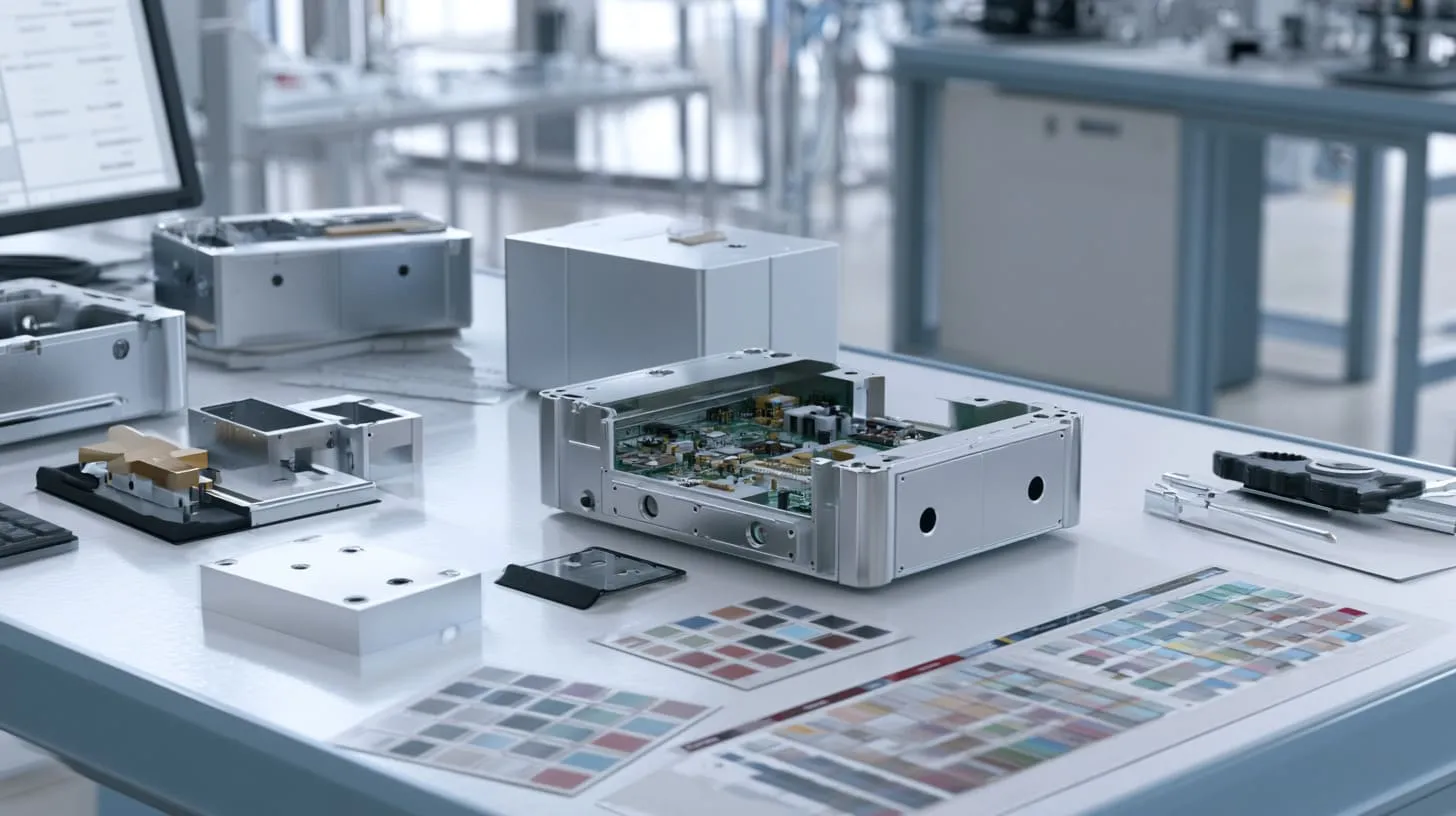
Before we start production, we try to understand what the enclosure must do.
This sounds basic. But it is very important.
A custom enclosure is not only a metal shell. It protects electronics. It carries a brand. It supports assembly. It may need to survive outdoor use, vibration, heat, dust, water, or repeated handling.
At MaidaTech, I prefer to find tolerance risk before quoting or sampling, because fixing a drawing on the screen is much cheaper than fixing 500 finished enclosures on the workbench.
Drawing Review and Manufacturability Check
The first step is drawing review.
We check whether the requested tolerance matches the manufacturing process. CNC, extrusion, sheet metal, and die casting all have different tolerance behavior.
We also check whether the design is easy to manufacture or quietly risky.
| Review Area | What We Check |
|---|---|
| Material | Aluminum grade, thickness, formability |
| Process | CNC, extrusion, sheet metal, die casting |
| Critical holes | PCB and connector alignment |
| Surface finishing | Anodizing, powder coating, masking |
| Assembly | Screws, covers, end plates, gaskets |
| Appearance | Visible surfaces and logo area |
If we see a risk, we prefer to discuss it early.
For example, if a customer requests a very tight sliding cover with powder coating, we may suggest more clearance or masking. If a bent aluminum part uses 6061 with a tight bend radius, we may suggest 5052 or redesign the bend.
This is not about saying no. It is about making the design easier to produce.
Critical Dimension Confirmation With the Customer
After the first review, we confirm critical dimensions.
I like to ask practical questions:
- Which holes match the PCB?
- Which cutouts match connectors?
- Which surfaces are used for sealing?
- Which dimensions are visible to the end user?
- Which areas need coating?
- Which areas must stay uncoated?
- Which dimensions must be checked after finishing?
These questions help both sides.
| Customer Information | Why It Helps |
|---|---|
| PCB drawing | Confirms standoff and connector alignment |
| Connector model | Confirms opening size and clearance |
| Gasket size | Confirms groove design |
| Surface finish requirement | Confirms coating allowance |
| Assembly method | Confirms screw and cover fit |
| Use environment | Confirms sealing and material choice |
Sometimes customers think these questions slow the project down. I understand that feeling. But unclear details slow the project much more later.
A few clear answers at the beginning can prevent many emails after sampling.
Sample Validation Before Mass Production
Sampling is very important for custom enclosure projects.
A sample shows what the drawing cannot fully explain. It shows assembly feel, coating result, sliding fit, screw fit, gasket contact, and appearance.
For ODM projects, sampling is even more important because the product may be new. The customer may still be adjusting the PCB, connector, or internal layout.
| Sample Check | What We Learn |
|---|---|
| PCB assembly | Board alignment and screw fit |
| Connector fit | Opening position and clearance |
| Sliding cover | Real finished fit |
| Surface finish | Color, texture, coating buildup |
| Gasket sealing | Compression and contact |
| Logo process | Engraving or printing appearance |
I prefer to test samples in finished condition. Raw samples are useful, but they do not tell the full story.
If the mass production part will be black anodized, powder coated, or masked, the sample should reflect that as much as possible.
Quality Control During Production
Quality control should focus on real risk.
Of course, general dimensions must be checked. But the most important dimensions are the ones that affect function.
For a custom aluminum enclosure, QC may include:
- Incoming material check
- First article inspection
- CNC dimension inspection
- Hole and thread check
- Surface finish check
- Coating thickness review if needed
- Assembly test
- Final visual inspection
- Packing check
| QC Focus | Purpose |
|---|---|
| Critical dimensions | Protect assembly |
| Thread quality | Avoid screw problems |
| Connector openings | Protect interface fit |
| Gasket area | Protect sealing |
| Surface finish | Protect appearance |
| Packaging | Avoid shipping damage |
A good QC plan should match the product risk.
If the enclosure is for an outdoor communication device, sealing and coating may be very important. If it is for an indoor desktop device, appearance and connector alignment may matter more.
The inspection plan should follow the project, not a fixed checklist copied from another product.
Conclusion
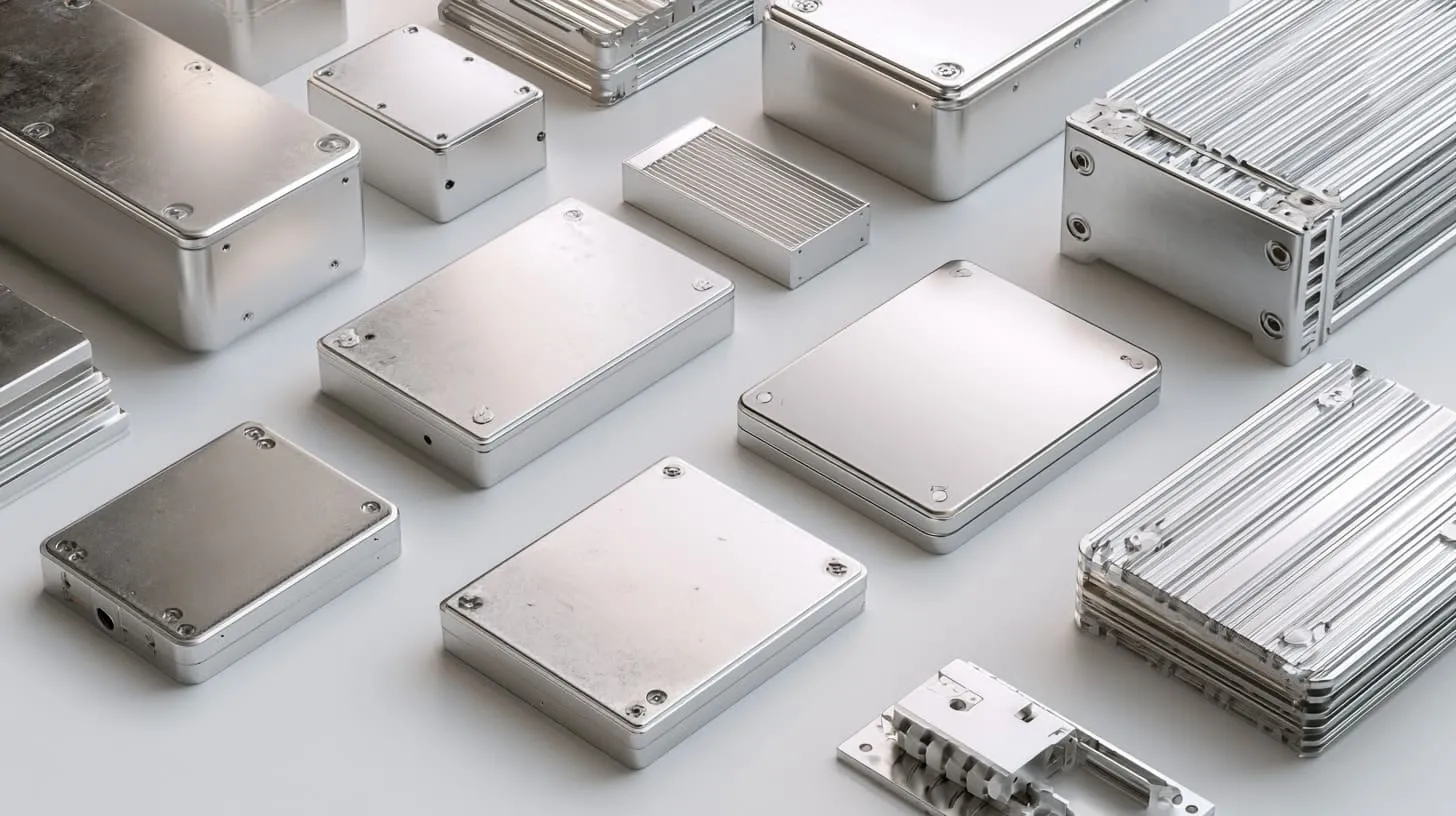
Standard tolerance is not just a factory rule.
I see it as a design decision.
This is why I do not like treating every dimension as equally important. A custom aluminum enclosure has many different jobs. It must hold the PCB, match the connectors, protect the electronics, support the brand, and assemble smoothly. Some dimensions carry real risk. Some dimensions only need normal control.
The smart way is to separate them.
Standard Tolerance Is a Design Decision, Not Just a Factory Rule
I think tolerance should always connect back to function.
If a dimension affects the PCB, connector, gasket, sliding cover, screw assembly, or sealing result, it deserves more attention. If a dimension only controls a non-critical outer surface, standard tolerance is often enough.
This is not lowering quality. This is choosing quality more carefully.
Good tolerance planning balances:
- Product function
- Manufacturing process
- Surface finishing
- Assembly speed
- Inspection cost
- Lead time
- Final customer experience
If every dimension is tight, the project becomes expensive. If no dimension is controlled, the project becomes risky.
The right answer is usually in the middle.
The Best Aluminum Enclosure Drawings Separate Function From Appearance
The best drawings I receive are not always the most complicated drawings.
They are the clearest drawings.
They show which dimensions are critical. They define the right datums. They clarify whether dimensions apply before or after finishing. They note masking areas. They separate cosmetic surfaces from functional interfaces.
That kind of drawing helps the factory quote faster, produce more smoothly, and inspect more accurately.
It also helps the buyer avoid surprises.
Final Advice for OEM and ODM Buyers
If you are designing a custom aluminum enclosure, I suggest you confirm these points before production:
| Question | Why It Matters |
|---|---|
| What process will be used? | CNC, extrusion, and sheet metal have different tolerance behavior |
| Which dimensions are critical? | QC should focus on real risk |
| Does coating affect fit? | Finished dimensions may change |
| Are connector openings checked with real parts? | Prevent interface problems |
| Is the gasket design reviewed? | Protect IP rating |
| Is a sample needed before mass production? | Reduce mass production risk |
I think this way because I have seen too many enclosure problems start from small tolerance assumptions.
A buyer wants high quality. The engineer wants tight control. The factory wants stable production. These goals do not have to fight each other. But they need a clear tolerance plan.
If you are working on a custom aluminum enclosure, you can send us your drawing, PCB layout, connector list, or rough concept. At MaidaTech, we can help review the tolerance risk, manufacturing process, surface finishing allowance, and assembly details before production.
A good enclosure does not come from making every number tight.
It comes from knowing which numbers truly matter.