Skip to content
A clean drawing can make people feel safe.
The hole size is there. The screw position is there. The tolerance looks clear. The finish note also looks simple: powder coating, black.
But in real enclosure production, this small finish note can change many things. It can change the final size of a hole. It can change how a screw goes in. It can make a cover feel too tight. It can also make a gasket seal unevenly.
I have seen this many times in custom aluminum enclosure and sheet metal enclosure projects. Before coating, the part looks correct. After coating, the customer starts testing the assembly, and then the problem appears.
The part did not become “bad” suddenly. The real issue is that the coating thickness was not included in the mechanical tolerance plan.
Powder coating is not only about color and surface protection. It is also a layer of material. Once this layer is added to the enclosure, the final dimensions change.
For product engineers, buyers, and OEM project owners, this small detail can decide whether a project runs smoothly or gets stuck during assembly.
What Is Powder Coating Thickness?
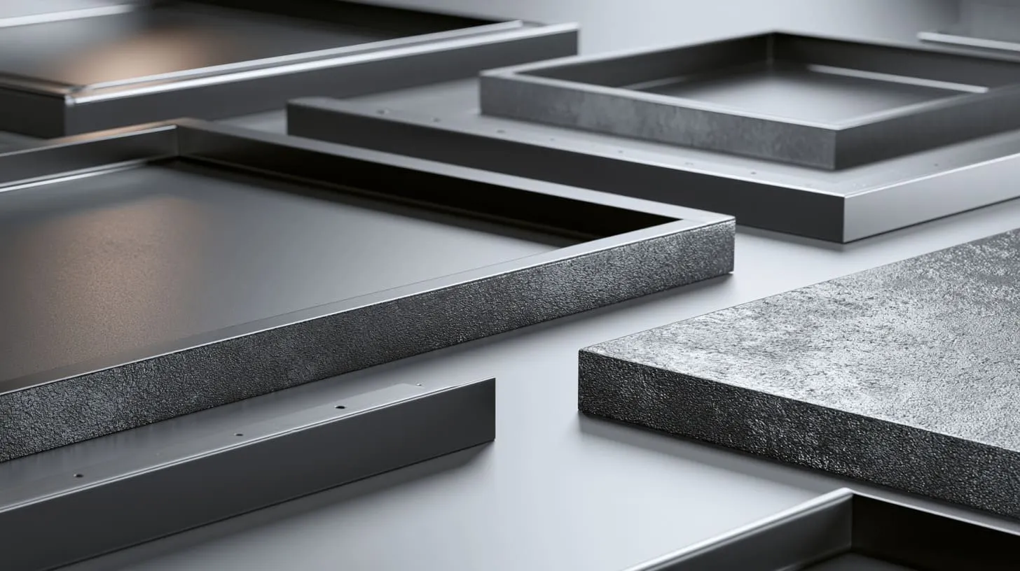
Powder coating thickness means the cured coating layer on the metal surface after spraying and baking.
It sounds simple. But it is not just a number on a coating report. It becomes part of the final product size.
For custom enclosures, I usually treat powder coating thickness as a design factor, not only a surface finish factor, because the final user does not assemble the raw metal part. They assemble the coated part.
Typical Powder Coating Thickness Range
In many enclosure projects, standard powder coating thickness is often around 50–125 microns. Some projects may be thinner. Some may be thicker. It depends on the powder type, color, texture, coating process, and protection requirement.
Here is a simple reference table:
| Coating Thickness | Common Situation | Possible Risk |
|---|---|---|
| 40–60 microns | Thin coating, light protection | Weak edge coverage, lower durability |
| 60–90 microns | Common powder coating range | Usually balanced for appearance and function |
| 90–125 microns | Thicker protection or texture finish | Higher risk for tight holes and fitting areas |
| Above 125 microns | Special requirement or heavy buildup | Assembly problems may increase |
A thicker coating may protect the surface better. It may also give a stronger texture. But it can create trouble when the enclosure has tight holes, sliding covers, connector openings, or gasket grooves.
A thinner coating may reduce assembly risk. But it may not protect sharp edges well enough.
This is the trade-off.
Why Thickness Is Not Always Uniform
Many buyers imagine coating thickness like a perfect skin on the whole enclosure.
In reality, powder coating does not behave like that.
It may be thicker on some outer surfaces. It may be thinner near sharp edges. It may build up around corners. It may enter holes unevenly. It may not cover deep internal areas in the same way as flat surfaces.
| Area of Enclosure | Coating Behavior | Why It Matters |
|---|---|---|
| Flat outer panel | Easier to control | Good for appearance inspection |
| Sharp edge | May have weak coverage | Higher corrosion risk |
| Hole edge | May build up around opening | Connector or screw fit may change |
| Internal corner | May receive uneven coating | Assembly or sealing may be affected |
| Deep recess | Harder to coat evenly | Hidden quality risk |
This is why one coating thickness number cannot explain the whole part.
If a supplier only measures one flat surface and says “thickness is okay,” I still do not relax immediately. The flat surface is the easiest place to pass inspection. The risky areas are often the holes, slots, grooves, and contact points.
Why Enclosure Buyers Should Care
For many OEM enclosure buyers, powder coating is chosen for three simple reasons:
- The color looks good.
- The surface feels protected.
- The brand needs a certain finish.
These reasons are valid. I understand them.
But if the buyer only sees powder coating as appearance, the project may miss the mechanical risk.
A product engineer may design the enclosure based on raw aluminum or raw sheet metal dimensions. The purchasing team may send the RFQ and focus on price, color, lead time, and logo printing. The coating supplier may finish the surface according to normal practice.
Each person does their job.
But nobody checks the final coated assembly.
That is where trouble starts.
A customer may say, “The sample looked perfect.” Then they install the PCB and find the standoff screw is too tight. Or they install the RJ45 connector and find the opening is slightly small. Or they close the lid and feel it scratches the body.
The surface looks good. The function does not.
That is the painful part.
A drawing can look complete, but if it does not define coating effect clearly, it still leaves room for misunderstanding. This is exactly why the next question matters: how does this coating layer change the real tolerance?
How Powder Coating Changes Mechanical Tolerances
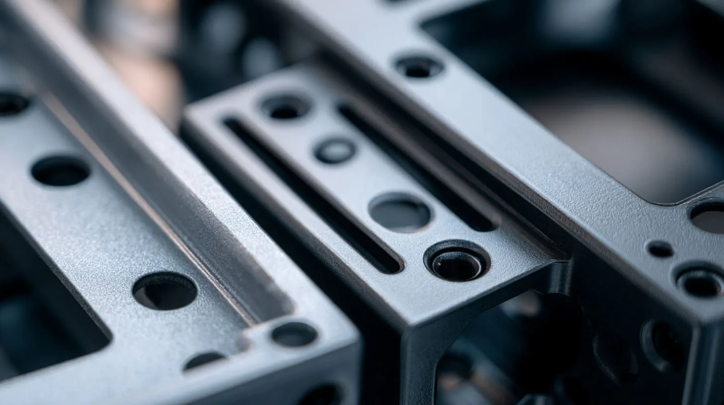
Powder coating changes tolerance because it adds thickness to the surface.
This is easy to say. But in real projects, people often forget to calculate it.
The way I judge this is simple: I do not only ask whether the raw part can be made within tolerance. I ask whether the final coated part can still assemble smoothly with real screws, real connectors, and real internal parts.
Coating Adds Material to Each Surface
Powder coating increases the size of outside surfaces. It also reduces the open space inside holes, grooves, slots, and mating areas.
For example, if a coating layer is 80 microns thick on one side, then a slot coated on both sides may lose around 160 microns of clearance.
That is not a big number for a large cover.
But it can be a big number for a tight connector opening.
| Feature | Coating Effect | Real Result |
|---|---|---|
| Outer wall | Size becomes slightly larger | Usually acceptable |
| Round hole | Inner diameter becomes smaller | Screw or gland may not fit |
| Slot | Slot width becomes smaller | Sliding or insertion may fail |
| Cover edge | Gap becomes smaller | Cover may scrape |
| Gasket groove | Groove depth changes | Sealing pressure may change |
This is why I always look at coated surfaces in pairs.
One surface coated? Small effect.
Two opposite surfaces coated? Bigger effect.
Several parts all coated and assembled together? Now the stack-up becomes real.
Tight Tolerances Become Risky After Coating
A tolerance can be correct before coating and wrong after coating.
This is the part that many people dislike hearing. But it is true.
Let’s say a drawing gives a tight hole tolerance. The CNC machining is accurate. The raw part passes inspection. Then the part goes to powder coating. After coating, the hole becomes smaller. The customer tests the connector. It does not fit well.
Who is wrong?
The machining supplier may say, “We made it according to the drawing.”
The coating supplier may say, “This is normal powder coating thickness.”
The customer may say, “But the finished part cannot assemble.”
Everybody has a reason. But the project is still stuck.
This is why the drawing should define whether critical dimensions are checked before coating or after coating.
| Drawing Condition | What It Means | Risk Level |
|---|---|---|
| Raw part tolerance only | Dimension is checked before coating | High risk for tight assembly |
| Finished part tolerance | Dimension is checked after coating | Better for functional control |
| No clear note | Supplier may guess | Very high misunderstanding risk |
| Masking note included | Some areas remain uncoated | Better for threads/contact areas |
For OEM enclosures, this is not a small paperwork detail. It is a practical production decision.
Why “Small Thickness” Can Still Cause Big Problems
Many customers see 60 or 80 microns and think, “That is too small to matter.”
I understand this feeling.
But mechanical fit does not care about feelings.
A screw thread can feel tight because of a small coating layer. A PCB can sit slightly unevenly because a boss height changes. A connector can fail to sit flush because the opening edge has coating buildup.
Small numbers can create big headaches when the design is already tight.
Here are some common examples:
| Small Coating Change | Possible Problem |
|---|---|
| Coating inside M3 thread | Screw becomes hard to install |
| Coating around RJ45 cutout | Connector clip rubs or blocks |
| Coating on sliding rail | Cover becomes too tight |
| Coating in gasket groove | Gasket compression becomes uneven |
| Coating on grounding surface | Electrical contact becomes unstable |
In one project, a customer sent a compact aluminum enclosure for a control board. The outside looked very clean after black powder coating. But the top cover was hard to close. The reason was not a big mistake. It was only coating buildup around the edge. But for that design, the gap was already too small.
A small layer became a big assembly issue.
This is also why I do not like to discuss coating only at the end of a project. Once the metal is already made, the options become fewer. Before production, a small drawing note can save many problems. After production, the same issue becomes rework, delay, and argument.
Which Enclosure Features Are Most Affected?
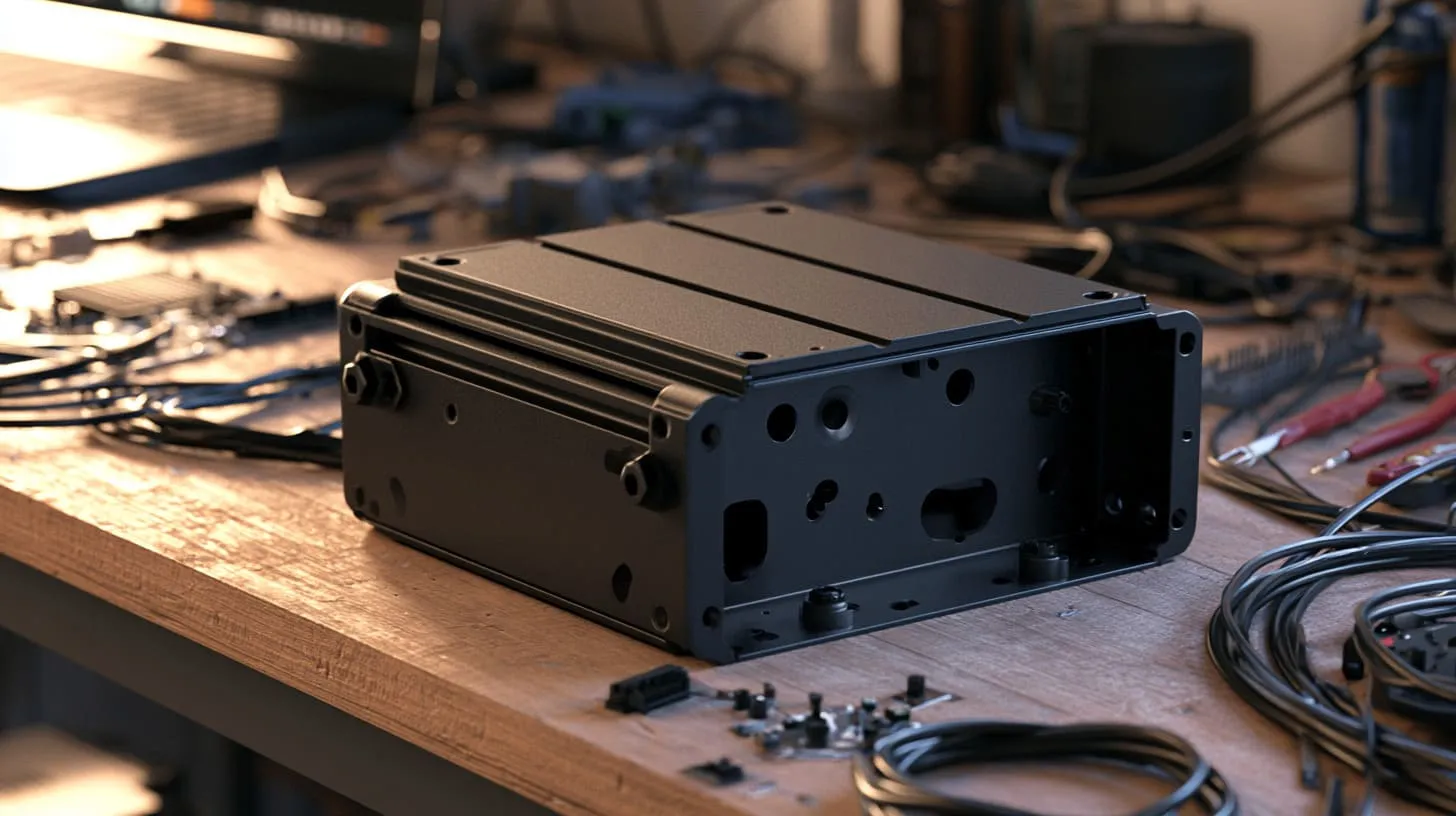
Not every surface has the same risk.
A large outer panel can usually accept powder coating without much problem. But small functional areas are different. These areas decide whether the enclosure can be assembled and used.
When I review a coated enclosure drawing, my eyes go first to the small functional details, not the big cosmetic surface, because the visible panel may impress the buyer, but the tiny hole is often the part that stops production.
Screw Holes and Threaded Holes
Threaded holes are one of the most common problem areas.
If powder coating enters a threaded hole, the screw may become tight. Sometimes the screw can still go in, but the torque feels strange. Sometimes the screw gets stuck. Sometimes the worker forces it, and then the thread is damaged.
This can happen with:
- Tapped holes
- Blind threaded holes
- PEM nuts
- Threaded inserts
- Grounding screws
- Cover screws
- PCB mounting screws
| Thread Area | Possible Issue | Better Control Method |
|---|---|---|
| Tapped hole | Screw cannot enter smoothly | Mask before coating or tap after coating |
| Blind hole | Coating collects inside | Use plug masking |
| PEM nut | Thread blocked | Use proper silicone plug |
| Grounding screw hole | Poor electrical contact | Keep contact area bare |
| Small screw hole | Torque becomes unstable | Test with real screws |
For repeat OEM orders, I usually prefer a clear masking plan. It looks like extra work at the beginning, but it reduces trouble during assembly.
Connector Cutouts and Cable Openings
Connector openings are another high-risk area.
RJ45, USB, HDMI, SMA, antenna holes, cable glands, and switch cutouts all need enough clearance after coating.
A connector drawing may show a required panel cutout size. But that size usually assumes a finished opening. If the enclosure opening is made exactly to that size before coating, the final opening may become too small.
| Connector Type | Risk After Coating | What I Check |
|---|---|---|
| RJ45 | Clip area may rub | Final coated opening size |
| USB | Metal shell may not fit cleanly | Width and corner clearance |
| SMA | Hole may become tight | Thread and washer fit |
| HDMI | Plug opening may be blocked | Edge buildup |
| Cable gland | Gland thread may not pass | Hole diameter after coating |
| Rocker switch | Snap fit may fail | Panel thickness and cutout size |
This is why I always like to see the connector datasheet or at least the real connector model.
A drawing with only “USB hole” is not enough.
Different connector brands may need slightly different openings. If the coating is added and the clearance is already small, the issue becomes even worse.
Cover-to-Body Assembly Clearance
Covers, lids, sliding panels, and side plates can also become too tight after coating.
This is easy to miss because the parts may look fine separately. The body looks good. The cover looks good. But when they are assembled, the problem appears.
Maybe the lid scrapes the side wall.
Maybe the screw holes do not align smoothly.
Maybe the cover closes, but the gap is uneven.
Maybe the sliding plate feels rough.
| Assembly Area | Possible Coating Effect | Result |
|---|---|---|
| Lid edge | Coating buildup | Cover hard to close |
| Sliding rail | Reduced clearance | Scratching or jamming |
| Side panel groove | Narrower slot | Panel cannot slide smoothly |
| Screw boss alignment | Small dimensional change | Screw difficult to start |
| Corner joint | Coating stack-up | Uneven gap |
For custom aluminum extrusion enclosures, this can be very important. Many extruded enclosures use grooves, rails, and end plates. If all of these surfaces are coated, the clearance must be planned.
A smooth sample is not only about CNC accuracy. It is also about coating behavior.
PCB Mounting Areas and Internal Bosses
Inside an electronics enclosure, the PCB mounting area is not a cosmetic area. It is a functional area.
PCB standoffs need stable height. Mounting holes need accurate position. Screws need clean engagement. Grounding contact may need bare metal.
If powder coating changes these areas, the board may not sit well.
| PCB Area | Possible Issue | Why It Matters |
|---|---|---|
| Standoff top | Height changes | PCB may tilt |
| Mounting hole | Screw becomes tight | Assembly slows down |
| Grounding boss | Coating blocks contact | EMC or grounding risk |
| Internal wall | Clearance reduces | Board edge may touch |
| Heat transfer area | Coating blocks contact | Thermal path may weaken |
For some electronics projects, customers ask for full internal coating because they want a clean appearance. I always pause at this point.
Does the PCB need grounding?
Does the heat need to transfer to the enclosure?
Does the board sit close to the wall?
If yes, internal coating needs a deeper discussion.
Gasket Grooves and Sealing Surfaces
For IP-rated enclosures, gasket design is sensitive.
Powder coating can change the groove depth and the sealing surface. If the coating is too thick or uneven, the gasket may not compress in the expected way.
Too little compression may allow water or dust to enter.
Too much compression may deform the gasket or make the cover hard to close.
| Sealing Area | Coating Risk | Possible Result |
|---|---|---|
| Gasket groove | Groove depth changes | Wrong compression |
| Sealing land | Uneven coating | Uneven pressure |
| Corner area | Coating buildup | Local sealing gap |
| Screw area | Coating affects torque | Uneven cover pressure |
| Hinge side | Buildup changes closing | Cover alignment issue |
This matters for outdoor enclosures, industrial control boxes, junction boxes, and waterproof electronic housings.
A beautiful powder coated box is not enough if the gasket does not seal well.
The tricky part is that many of these problems are invisible before assembly. You cannot always see them from a photo. You need to test the part like the customer will use it. That leads to one practical question: should some areas be masked before coating?
How to Decide Whether to Mask Certain Areas
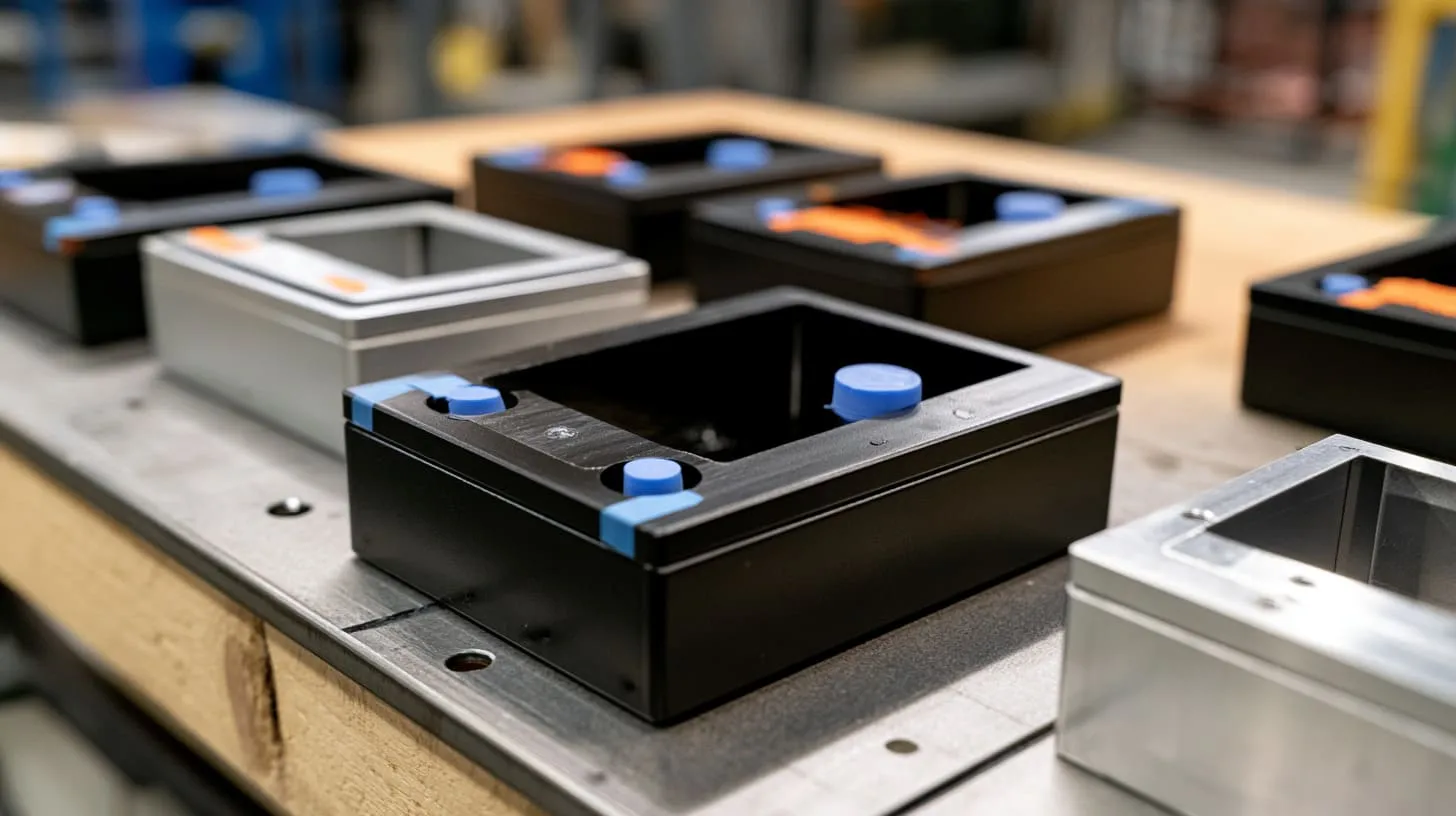
Masking means protecting certain areas from powder coating.
Some buyers think masking is only a small production detail. I see it differently. Masking is often the difference between a good-looking part and a usable part.
My decision is usually based on function first: if coating makes an area harder to assemble, weaker in contact, or unstable in sealing, I would rather discuss masking early than repair parts later.
When Masking Is Necessary
Masking is useful when powder coating should not enter or cover a functional area.
Common masking areas include:
- Threaded holes
- Grounding points
- Precision holes
- Sliding contact surfaces
- Heat transfer areas
- Gasket seating areas
- Connector cutout edges
- Press-fit areas
- Bearing or hinge contact surfaces
| Area | Should It Be Masked? | Reason |
|---|---|---|
| Threaded hole | Often yes | Keep screw engagement clean |
| Grounding surface | Usually yes | Keep metal contact |
| Cosmetic outer panel | Usually no | Coating is needed |
| Internal sliding rail | Often yes | Avoid friction or jamming |
| Gasket groove | Depends | Control sealing dimension |
| Heat transfer pad area | Often yes | Improve thermal contact |
Masking should not be random. It should follow the function of the part.
For example, if a hole is only for drainage, coating inside may not matter much. But if the same size hole is for a press-fit connector, it matters a lot.
Common Masking Methods
Different areas need different masking methods.
The factory may use silicone plugs, high-temperature tape, caps, or custom fixtures. The right choice depends on shape, quantity, tolerance, and repeat order needs.
| Masking Method | Common Use | Advantage | Limitation |
|---|---|---|---|
| Silicone plug | Round holes, threaded holes | Fast and reusable | Needs correct plug size |
| High-temp tape | Flat surfaces, contact areas | Flexible | Labor cost increases |
| Silicone cap | Studs, bosses, small features | Good for small protruding parts | Not suitable for all shapes |
| Custom fixture | Repeat OEM production | Stable and consistent | Higher setup cost |
| Manual cleanup after coating | Low-volume correction | Flexible | Risk of scratches and labor variation |
For prototype projects, simple masking may be enough.
For repeat production, I prefer a stable masking method. It makes inspection easier and reduces worker-to-worker variation.
Masking Cost vs Rework Cost
Masking costs money. Nobody should pretend it is free.
It takes labor. It takes planning. It may slow coating preparation. If the shape is complex, the cost can rise.
But rework also costs money.
And rework often costs more because it happens after the schedule is already tight.
| Choice | Short-Term Cost | Long-Term Risk |
|---|---|---|
| No masking | Lower at first | Higher risk of assembly failure |
| Basic masking | Moderate | Good for common functional areas |
| Detailed masking plan | Higher at first | Better for repeat OEM quality |
| Rework after coating | Unclear at first | Delay, scratches, rejects, argument |
I have seen customers try to save a small masking cost, then spend more time tapping coated holes, cleaning contact areas, or rejecting parts.
The problem is not only money.
The problem is timing.
When the customer is waiting for samples to test their own product, a three-day delay can feel much longer. If their product launch is close, even a small enclosure issue becomes very stressful.
This is why masking should be discussed before coating, not after coating. But masking alone cannot solve every problem. The whole OEM control method also matters.
How to Control Powder Coating Thickness in OEM Projects

OEM projects need more control than general stock parts.
A stock enclosure can accept a wider range in many cases. A custom OEM enclosure may need to match a PCB, connector, gasket, bracket, logo position, and customer assembly process.
For me, the most dangerous RFQ is not the one with many requirements. The most dangerous RFQ is the one with vague requirements but tight expectations.
Define Finished Dimensions Clearly
The drawing should make clear whether important dimensions are measured before coating or after coating.
This sounds basic. But it is often missing.
A simple note can avoid many arguments.
| Drawing Note | Meaning | Better Use |
|---|---|---|
| All dimensions before coating | Raw part control only | Use only when coating does not affect function |
| Critical dimensions after coating | Functional size control | Best for holes, slots, grooves, mating areas |
| Powder coating all surfaces | General finish note | Too vague for functional areas |
| Mask area A/B/C before coating | Clear process control | Better for OEM production |
| Final assembly test required | Function control | Good for first article inspection |
If a customer gives a tight tolerance on a coated feature, I want to know whether they really need that tolerance after coating.
Sometimes they do.
Sometimes it is only a copied tolerance from an old drawing.
These two situations are very different.
Separate Critical and Non-Critical Areas
Not every dimension needs tight control.
This is important because over-controlling every area increases cost and creates more rejection risk.
A large cosmetic outer panel does not need the same tolerance strategy as a connector opening. A logo surface does not need the same control as a grounding boss.
| Area Type | Tolerance Control | Reason |
|---|---|---|
| Connector cutout | Tight after coating | Must fit real connector |
| Threaded hole | Process controlled | Screw must install smoothly |
| PCB standoff | Tight and functional | Board position matters |
| Outer cosmetic face | More flexible | Appearance matters more than exact size |
| Hidden inner wall | Depends on clearance | Check PCB and cable space |
| Gasket groove | Functional control | Sealing depends on compression |
Good tolerance control is not about being strict everywhere.
It is about being strict where failure matters.
This is a very practical way to reduce cost while keeping the important functions safe.
Use Realistic Tolerance Allowances
A coating layer needs space.
If the raw metal design has no allowance, the coating will steal clearance from the assembly.
For example, if a slot needs a final opening of 10.00 mm, and both sides are coated, the raw slot may need to be larger. The exact value depends on target coating thickness and tolerance.
A simple example:
| Item | Example Value |
|---|---|
| Required final slot width | 10.00 mm |
| Coating thickness per side | 0.08 mm |
| Total buildup on two sides | 0.16 mm |
| Possible raw slot width | Around 10.16 mm or more |
| Final decision | Depends on tolerance and coating control |
This example is simple, but the thinking is useful.
Do not only ask, “Can you make this hole?”
Ask, “Can this hole still work after coating?”
That is the real question.
Confirm Coating Thickness Standard Before Production
Before production, the customer and supplier should confirm:
- Powder type
- Target thickness
- Color
- Gloss level
- Texture
- Masking areas
- Inspection points
- Final assembly test
- Sample and mass production process
| Item to Confirm | Why It Matters |
|---|---|
| Target thickness | Controls size and protection |
| Color and gloss | Controls appearance |
| Texture | May increase apparent thickness |
| Masking plan | Protects functional areas |
| Inspection method | Avoids vague acceptance |
| Coating supplier | Keeps process stable |
| Sample approval standard | Prevents mass production surprise |
One hidden issue is supplier change.
A sample may be coated by one applicator. Mass production may be coated by another. If the process control is not clear, the coating thickness may change.
The color may still look acceptable.
But the fit may change.
That is why I prefer to lock the key coating standard before mass production.
Good control does not mean making the project complicated. It means removing unclear areas before they become expensive. Once the coated parts arrive, inspection becomes the next gate.
Powder Coating Thickness and Quality Inspection

Inspection should not stop at surface appearance.
A powder coated enclosure can look beautiful and still fail during assembly. This is not rare. It happens because visual quality and mechanical quality are not the same thing.
When I check coated samples, I do not trust the color first. I trust the assembly test first, because the customer will not sell a color sample. They will sell a working product.
How Coating Thickness Is Measured
Powder coating thickness is often checked with a film thickness gauge.
The gauge can measure the cured coating layer on the metal surface. This helps confirm whether the coating is within the agreed range.
But the inspection point matters.
If the operator only measures a large flat outside surface, the report may look good. But the problem may be inside a hole, around a cutout, or near a corner.
| Inspection Area | Should It Be Checked? | Reason |
|---|---|---|
| Large outer surface | Yes | Main appearance area |
| Near cutouts | Yes | Buildup may affect fit |
| Around screw holes | Yes, if possible | Fastener risk |
| Gasket surface | Yes | Sealing risk |
| Internal mounting area | Yes if functional | PCB and grounding risk |
| Hidden deep recess | Depends | Check if function is affected |
For normal cosmetic parts, a few representative points may be enough.
For precision OEM enclosures, critical areas need more attention.
Why Visual Inspection Is Not Enough
Visual inspection can catch many problems:
- Color mismatch
- Orange peel
- Scratches
- Poor coverage
- Dirt
- Uneven gloss
- Exposed metal
But it cannot fully confirm mechanical fit.
A hole that looks clean may still be too small. A thread that looks coated may not accept a screw smoothly. A gasket groove may look fine but compress incorrectly.
| Visual Result | Hidden Functional Risk |
|---|---|
| Nice black finish | Thread may be blocked |
| Smooth outside surface | Connector opening may be tight |
| Clean edge | Coating may chip during assembly |
| Even gloss | Gasket compression may still fail |
| Good photo | Real PCB may not sit flat |
This is why sample photos are not enough for important projects.
Photos are useful. Videos are better. Real assembly testing is best.
First Article Inspection for Coated Parts
For coated OEM enclosures, first article inspection should include both dimensions and assembly.
I like to check the part in the same way the customer will use it.
That means testing:
- Real screws
- Real PCB
- Real connector
- Real gasket
- Real cover
- Real bracket
- Real cable gland
- Real grounding contact, if needed
| First Article Check | What It Confirms |
|---|---|
| Screw installation | Threads and holes are usable |
| Connector fit | Cutouts are correct after coating |
| Cover closing | Assembly clearance is enough |
| Gasket compression | Sealing design still works |
| PCB mounting | Internal height and position are correct |
| Grounding point | Bare metal contact is stable |
| Surface thickness | Coating process is controlled |
A first article is not only a sample. It is a truth test.
It tells both sides whether the design, coating, tolerance, and assembly method are working together.
If the first article fails, it is better to find out early.
Finding the problem after 1,000 pieces are coated is a very different feeling.
Many coating problems do not come from one big mistake. They come from small ignored details. That is why I want to look at the common mistakes clearly.
Common Mistakes in Powder Coated Enclosure Design
Most powder coating tolerance problems are avoidable.
They usually happen because people make assumptions. The buyer assumes the supplier will handle it. The supplier assumes the drawing is complete. The coating shop assumes normal coating is fine.
This is where I become careful: when everyone thinks a detail is “standard,” I know nobody may actually be controlling it.
Using Raw Metal Tolerances for Finished Parts
This is the most common mistake.
The drawing defines the raw metal size. The supplier makes the raw part correctly. Then coating changes the final dimension. The customer tests the final part and finds a problem.
The argument starts because the inspection standard was not clear.
| Situation | What Happens |
|---|---|
| Raw part passes inspection | Machining looks correct |
| Coating adds thickness | Final size changes |
| Assembly fails | Customer rejects part |
| Drawing is unclear | Responsibility becomes hard to define |
The simple fix is to mark critical dimensions as final coated dimensions when needed.
Not all dimensions need this. But functional ones do.
Ignoring Double-Side Buildup
Many people calculate coating thickness on one side only.
But holes, slots, and grooves often have two opposite coated surfaces. That means the clearance loss can double.
| Feature | One-Side Thinking | Real Thinking |
|---|---|---|
| Slot | Coating adds 0.08 mm | Both sides may reduce 0.16 mm |
| Round hole | Small coating layer | Diameter reduces from all around |
| Groove | Bottom only | Side walls also affect fit |
| Sliding rail | One surface | Two contact surfaces may rub |
This is a small math mistake, but it creates real assembly pain.
For tight features, always think in pairs.
Forgetting Threads and Fasteners
Threads are easy to forget because they are small.
But assembly workers feel this problem immediately.
If screws do not go in smoothly, production slows down. If workers force screws, threads may be damaged. If torque becomes unstable, the final product may not feel reliable.
Common fastener risks include:
- Coated tapped holes
- Coated PEM nuts
- Coated screw seats
- Coated countersunk areas
- Coated grounding screws
| Fastener Issue | Possible Result |
|---|---|
| Coating in thread | Screw difficult to install |
| Coating on screw seat | Screw head not sitting flat |
| Coating on grounding screw area | Poor contact |
| Coating in countersink | Head height changes |
| Coating on PEM nut | Thread blocked |
A screw hole is not just a hole. It is part of the assembly experience.
If the customer’s worker struggles with every screw, the enclosure feels low quality even if the surface looks nice.
Over-Specifying Tight Tolerances Everywhere
Some drawings are too strict in every area.
I understand why this happens. Engineers want control. Buyers want quality. Nobody wants loose parts.
But tight tolerance everywhere does not always mean better quality.
It can mean higher price, longer lead time, more rejects, and more arguments.
| Tolerance Strategy | Result |
|---|---|
| Tight everywhere | Higher cost and rejection risk |
| Loose everywhere | Assembly and quality risk |
| Tight only where needed | Better balance |
| Clear functional control | Easier production and inspection |
The better way is to define what really matters.
If a connector must fit, control that opening. If a gasket must seal, control that groove. If an outer panel only needs to look clean, do not treat it like a precision bearing surface.
Changing Coating Supplier After Sample Approval
This mistake is painful because the sample may be approved already.
The customer likes the sample. The color is right. The fit is good. The surface feels fine.
Then mass production uses another coating shop, another powder batch, another operator, or another process setting.
The result may change.
| Change After Sample | Possible Risk |
|---|---|
| Different coating supplier | Different thickness behavior |
| Different powder brand | Color or texture variation |
| Different operator | Uneven film thickness |
| Different hanging method | Coating marks or buildup changes |
| Different curing condition | Surface quality changes |
For repeat OEM orders, sample approval should include process control.
It should not only say, “The black color looks okay.”
It should also confirm the thickness range, masking plan, inspection method, and critical assembly result.
These mistakes are not hard to understand. But they are easy to ignore when the project is moving fast. So before finalizing a drawing, I like to slow down and ask a few practical questions.
Practical Design Recommendations for Product Engineers
A product engineer does not need to become a powder coating expert.
But they should know where coating can disturb the mechanical design.
The smartest engineers I work with are not the ones who make the most complex drawings. They are the ones who ask the right questions before the part is made.
Before I accept a tight coated enclosure requirement, I always want to understand how the part will be assembled in the real product, because CAD clearance and hand assembly are not always the same world.
Ask These Questions Before Finalizing the Drawing
Before locking the drawing, I suggest asking these questions:
| Question | Why It Matters |
|---|---|
| Which dimensions are critical after coating? | Avoid wrong inspection standard |
| Which holes need masking? | Protect screw and connector fit |
| Does the enclosure need grounding? | Avoid coating blocking contact |
| Does the PCB need heat transfer to the case? | Avoid coating on thermal path |
| Will the gasket still compress correctly? | Protect IP performance |
| Are connector openings large enough after coating? | Avoid assembly failure |
| Will the cover slide or close smoothly? | Avoid scraping and tight fit |
| Is the sample coating process same as mass production? | Avoid production variation |
These questions are simple. But they are powerful.
They force the project team to think about the finished product, not only the drawing.
Mark Critical Areas Clearly on the Drawing
A clear drawing saves time.
If an area must be masked, mark it.
If a dimension must be checked after coating, mark it.
If a grounding area must be bare metal, mark it.
If a thread must be clean, mark it.
Do not leave these points for guessing.
| Drawing Note | Better Than |
|---|---|
| Mask threaded holes before powder coating | “Powder coating all surfaces” |
| Keep grounding area uncoated | “Black coating required” |
| Final coated opening must fit connector drawing | “Cut hole as drawing” |
| Check gasket groove after coating | “Waterproof design” |
| Tap threads after coating if needed | No thread process note |
Vague notes create different interpretations.
Clear notes create shared responsibility.
This is very important when the buyer is in Europe or North America and the supplier is in China. Time zone differences already slow communication. A vague drawing makes this worse.
Test Assembly Before Mass Production
A coated sample should not only sit on the table for photos.
It should be assembled.
I always suggest testing the sample with the real parts:
- Real PCB
- Real screws
- Real gasket
- Real cable glands
- Real connectors
- Real brackets
- Real labels or logo position
- Real installation method
| Test Item | Pass Standard |
|---|---|
| Screw installation | Smooth, no forced torque |
| PCB mounting | Board sits flat |
| Connector fit | No rubbing or blocking |
| Cover assembly | Closes smoothly |
| Gasket compression | Even pressure |
| Grounding test | Contact is stable |
| Surface check | No coating damage after assembly |
This is where many hidden problems become visible.
A design can look good in CAD. A machined part can look good before coating. A powder coated enclosure can look good in photos.
But the real answer comes when everything is assembled together.
That is why I prefer early sample testing instead of arguing after mass production. And this is also why our own process at MaidaTech starts from drawing review, not only quotation.
How MaidaTech Handles Powder Coating Tolerance Risks

At MaidaTech, we make custom aluminum enclosures, plastic enclosures, sheet metal enclosures, and OEM enclosure projects for different customers.
Many customers send us drawings with powder coating notes. Some drawings are very complete. Some are only basic. Some customers know exactly what they need. Some only know the color and outside size.
I do not blame customers for this.
Enclosure projects sit between design, manufacturing, surface finishing, electronics, and final assembly. It is normal for some details to be unclear at the beginning.
My habit is to catch the risky details before they become production problems, because a cheap quotation is not useful if the customer receives parts that cannot assemble.
Drawing Review Before Quotation
Before quoting a custom coated enclosure, we usually review the drawing from a manufacturing and assembly view.
We check areas such as:
- Holes
- Threads
- Connector openings
- Cover fit
- Sliding grooves
- Gasket grooves
- PCB mounting bosses
- Grounding points
- Heat transfer areas
- Surface finish notes
| Area We Check | What We Look For |
|---|---|
| Threaded holes | Need masking or post-tapping? |
| Connector cutouts | Enough clearance after coating? |
| Gasket groove | Will coating affect compression? |
| PCB bosses | Will board still sit flat? |
| Mating surfaces | Will coating make fit too tight? |
| Grounding area | Should it stay bare metal? |
| Heat contact area | Should coating be removed? |
If we see a risk, we try to raise it early.
This is not to make the project more complicated. It is to avoid a simple mistake becoming an expensive delay.
Sample Confirmation Before Bulk Order
For custom OEM projects, sample confirmation is very important.
A sample should confirm:
- Size
- Surface finish
- Coating thickness
- Masking areas
- Logo position
- Assembly fit
- Connector fit
- Screw installation
- Gasket sealing condition
- Packaging method
| Sample Check | Why We Care |
|---|---|
| Appearance | Customer brand image |
| Thickness | Protection and tolerance |
| Assembly | Real product function |
| Masking | Repeatable production control |
| Logo | Brand requirement |
| Packaging | Avoid shipping damage |
Some customers only check photos at the sample stage. I understand this when time is tight. But for tight tolerance enclosures, photos are not enough.
If possible, the customer should assemble the sample with their real internal parts.
That is the best way to approve the design.
Practical Factory Communication
Good enclosure production is not only about machines.
It is also about communication.
The customer understands the product. The factory understands manufacturing behavior. The coating supplier understands surface process. If these three sides do not connect, the project may look fine at the beginning and fail near the end.
This happens often in international sourcing.
A buyer in Finland, Belgium, Canada, Germany, or Hungary may send a drawing to China. The supplier replies at night because of time zone difference. One small unclear note may take two or three days to confirm.
That is why I like to make the questions specific.
Not “Please confirm coating.”
Better:
- Should these M3 holes be masked?
- Is this RJ45 cutout size final after coating?
- Does this internal boss need grounding contact?
- Should this gasket groove be measured after coating?
- Can we keep this thermal contact area uncoated?
Specific questions get specific answers.
And specific answers reduce project risk.
A custom enclosure is not only a metal box. It is part of the customer’s final product. If the coating thickness affects the tolerance, it affects the whole product experience. This is the reason I take this topic seriously.
Conclusion
Powder coating thickness may look like a small surface detail, but in custom enclosure projects, it can directly affect mechanical tolerances.
I think this way because I have seen the same problem repeat in different forms.
A screw hole is slightly tight.
A connector opening is slightly small.
A cover does not close smoothly.
A gasket does not compress evenly.
A PCB does not sit perfectly.
None of these problems looks dramatic at first. But each one can slow a project, delay a shipment, or damage customer confidence.
That is why I do not treat powder coating as only a color choice. I treat it as part of the mechanical design.
For OEM aluminum enclosures and sheet metal enclosures, the most important question is not only:
“Can we powder coat this part?”
The better question is:
“Can this part still assemble correctly after powder coating?”
This is why I suggest checking critical holes, threads, connector cutouts, mating surfaces, gasket grooves, PCB mounting points, grounding areas, and heat transfer areas before production.
I believe a good enclosure supplier should not only quote the drawing. A good supplier should help the customer find hidden risks in the drawing.
At MaidaTech, we support custom aluminum enclosures, plastic enclosures, sheet metal enclosures, and OEM/ODM enclosure projects with logo printing, engraving, surface finishing, and custom packaging.
If you are designing a powder coated enclosure and you are not sure whether the coating thickness will affect your tolerance, you can send us your drawing or STEP file. We can help review the risky areas before production, so your sample has a better chance to work the first time.