Skip to content
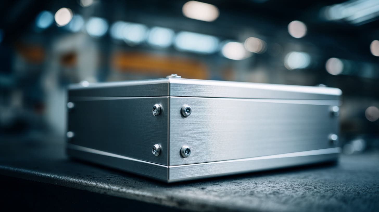
A metal enclosure can look clean, tight, and well made on the bench, yet still leak EMI through a line so small that people barely notice it.
That line is often the seam.
I have seen this problem confuse smart engineers, experienced buyers, and careful factory teams. The reason is simple. A seam can look fine and still fail in electrical terms. The screws are there. The lid sits flat. The surface finish looks premium. Everything feels under control. Then the EMC test report comes back with bad news, and the whole mood changes.
EMI leakage still surprises people because it does not always come from the dramatic things. It is often not the biggest part, the most complex PCB, or the boldest design feature. It is the overlooked detail. A coating that blocks contact. A gap that seems tiny. A screw layout that is good for structure but weak for shielding.
I do not judge an enclosure seam by how neat it looks after assembly. I judge it by whether it keeps a stable conductive path when the product is coated, tightened, moved, shipped, heated, cooled, and used in the real world.
That is where things get expensive fast.
A failed EMC test can push a project back by weeks. A redesign can mean new tooling work, new samples, new internal discussion, and more pressure between buyer and supplier. For OEM and ODM work, the seam is never just a technical detail. It can become a schedule problem, a cost problem, and a trust problem.
In this article, I want to break this topic down in a practical way. I will look at why seams leak, what engineers often miss, how frequency changes the risk, and what I think actually helps in real enclosure work.
The hard part is not understanding that seams matter. The hard part is respecting how many small things can quietly weaken them.
That is exactly why I want to start with the most basic question first.
What Is EMI Leakage at Enclosure Seams?

When I explain EMI leakage to buyers or junior engineers, I try not to make it sound like a physics lecture. In plain language, EMI leakage means unwanted electromagnetic energy is escaping from a product, or outside noise is getting in, because the shielding path is not doing its job.
At an enclosure seam, this usually happens where two metal parts meet but do not form a good electrical connection. On paper, the enclosure is metal, so people assume it should shield well. In real life, the seam can interrupt that shield like a crack in a wall.
A lot of confusion starts because people mix up being physically closed with being electrically continuous. Those are not the same thing.
Understanding EMI leakage in simple terms
EMI leakage usually shows up in two broad ways: radiated and conducted problems.
Radiated leakage is the one many people picture first. Energy escapes through openings, seams, slots, or weak contact areas and moves through the air. Conducted issues travel along cables, traces, or conductive paths. At seams, the radiated part is often the bigger concern, but the story is not always so neat.
A seam can act like a weak joint in the shield. It can also behave like a narrow slot. At certain frequencies, that slot can radiate more than people expect. This is why a seam that feels mechanically acceptable can still behave badly in EMC testing.
Here is a simple way I think about it:
| Condition | What it looks like mechanically | What it may do electrically |
|---|---|---|
| Tight seam with good bare-metal contact | Solid and well assembled | Usually supports shielding well |
| Tight seam with coating in contact area | Still looks good | May block conductivity |
| Small visible gap | Minor cosmetic issue to some people | Can become a leakage path |
| Uneven pressure along seam | Lid seems installed | Shielding may be inconsistent |
I often tell customers this: metal around electronics is not enough by itself. The metal has to stay electrically connected in the right places.
Why seams are critical in enclosure design
A full metal enclosure works as a shield only when current can move along its surface in a continuous way. Once that path is interrupted, the shield becomes weaker. The seam is where this interruption often starts.
One weak seam can reduce the value of an otherwise strong enclosure design. That sounds unfair, but I have seen it happen more than once. Teams focus on wall thickness, alloy choice, and attractive finishing, yet the real EMI problem sits where the lid meets the body.
My own way of checking this is very practical: if the seam depends on hope, appearance, or “it should be fine,” I already assume there is risk.
That is why seam design matters so much in shielding effectiveness. It is the meeting point of:
- Mechanical fit
- Surface finish
- Fastener pressure
- Tolerance control
- Assembly repeatability
- Long-term stability
Typical industries affected
This issue is not limited to one niche corner of electronics. I see it across many kinds of products:
- Industrial control boxes
- IoT devices
- Telecom hardware
- Test instruments
- Automation equipment
- Embedded systems
- Raspberry Pi-based custom projects
- Edge computing devices
For Raspberry Pi or custom SBC enclosure projects, this becomes even more interesting. A lot of these products start as compact, practical builds. The enclosure is treated as protection and branding. Later, as interfaces, clock speeds, wireless functions, and power density increase, the enclosure suddenly becomes part of the EMI story too.
| Industry or product type | Why seam leakage matters |
|---|---|
| Industrial electronics | Compliance risk and noise sensitivity |
| Telecom equipment | High-frequency behavior becomes critical |
| IoT devices | Compact housings leave less room for mistakes |
| Embedded systems | Mixed signal environments raise noise concerns |
| Raspberry Pi-based systems | Rapid custom development can skip EMI details |
That leads to the next problem, and in my experience it is one of the most common ones: the metal parts touch, but not well enough.
A seam does not fail only when there is a big gap. Sometimes it fails because the contact people trusted was never truly reliable.
Poor Metal-to-Metal Contact at the Seam

I have seen many seam problems come from one basic misunderstanding: people think any metal-to-metal contact is good contact.
It is not.
A seam can have contact in some areas and poor contact in others. It can look flat but still sit unevenly. It can be tight at one end and weak at the other. Once I learned to stop treating contact like an on-or-off condition, a lot of enclosure problems started making more sense.
Surface roughness and flatness issues
Surface quality matters more than many people expect. If two mating surfaces are not flat enough, contact becomes patchy. The seam may touch in a few raised spots, but not along the full path.
This can come from:
- Machining marks
- Stamping distortion
- Bending stress
- Warping after coating
- Poor fixture control in production
I have seen lid parts that looked excellent when laid on a table, yet once installed on the base they rocked slightly or pulled unevenly under screw pressure. That kind of flaw is easy to miss in a casual visual check.
Here is how I usually frame it:
| Surface issue | Common cause | EMI risk |
|---|---|---|
| Rough contact area | Tool marks, poor finishing | Reduced real contact area |
| Warped lid | Fabrication stress, handling | Uneven seam pressure |
| Bent flange | Forming error | Local gaps along seam |
| Burrs or edge damage | Incomplete deburring | False contact and unstable fit |
A nice-looking part can still have poor contact geometry. That is why I never trust cosmetics alone.
Insufficient contact pressure
Even when the surfaces are decent, the seam still needs pressure. Without enough pressure, the electrical path becomes weak or inconsistent.
This problem often shows up when:
- Screw count is too low
- Screw spacing is too wide
- Tightening sequence is poor
- Structural stiffness is weak
- Local bending happens near cutouts
From my side, I pay attention to whether the seam is being pressed evenly, not just firmly. Too many teams celebrate a tight center area and ignore the corners or edges.
A seam with uneven pressure is like a handshake with two fingers. It is technically contact, but I would not trust it much.
Oxidation and contamination
Aluminum brings another layer of trouble because aluminum oxide forms naturally. That oxide layer is useful for corrosion resistance, but it is not good for electrical conductivity. Dirt, oil, fingerprints, and shop contamination add even more uncertainty.
This is where things often go wrong in production. The design may look acceptable. The prototype may even pass a basic check. Then assembly handling adds a little oil, storage time adds a little oxidation, and the result becomes less stable.
| Contamination type | Source | Effect on seam |
|---|---|---|
| Oxide layer | Natural aluminum surface reaction | Raises contact resistance |
| Oil or grease | Machining, handling, assembly | Blocks clean contact |
| Dust or particles | Shop environment | Creates uneven local contact |
| Coating overspray | Incomplete masking | Interrupts conductive path |
I have learned to be suspicious of seam performance that depends on perfectly clean handling. Real production is never that kind.
Before I move to coatings, I should say this clearly: some of the worst seam issues come from parts that are made beautifully, then finished in a way that quietly kills conductivity.
That is why surface finish deserves its own section.
Impact of Surface Finishes on EMI Leakage

Surface finish creates some of the most frustrating EMI leakage problems because it improves appearance and corrosion resistance while sometimes hurting electrical contact.
This is the kind of trade-off that traps teams. A buyer wants a premium look. A brand wants color consistency. A product team wants durability. All of that is reasonable. The trouble starts when nobody asks what the finish is doing to the seam.
Anodizing and its insulating effect
Anodizing is popular for aluminum enclosures because it looks clean, professional, and durable. I understand why customers like it. I like it too for many projects. But anodizing builds an oxide layer, and that layer is insulating.
That means two anodized surfaces touching each other may look like metal contact while behaving more like blocked contact.
I do not reject anodizing by default. I only stop trusting it at the seam unless the conductive path is designed very intentionally.
Here is a simple comparison:
| Finish condition | Appearance | Corrosion resistance | Seam conductivity |
|---|---|---|---|
| Bare aluminum | Plain | Lower | Better if clean and tight |
| Full anodized surface | Premium | High | Poor at direct contact zones |
| Masked contact area + anodized exterior | Balanced | Good | Much better for shielding |
The hidden risk is psychological. People see an expensive finish and assume better overall quality. But EMI does not care how premium a part looks.
Powder coating and painting issues
Powder coating and paint create the same kind of danger in a different way. They form a physical barrier. If that barrier sits in the seam contact area, continuity suffers.
This problem is common in sheet metal enclosures. The box looks excellent after coating. The edges are protected. The color matches the brand. Then the seam stops behaving like a reliable electrical joint.
What makes this worse is that the coating may not be equally thick everywhere. So the contact becomes unpredictable. One batch may perform acceptably. Another may not.
I have seen teams spend hours discussing shielding material choice while ignoring a paint layer that already broke the path.
Selective masking strategies
Selective masking is one of the most practical ways to keep appearance and EMI performance in balance. The idea is simple: finish the visible areas, but leave the true contact zones conductive.
This sounds easy until production starts. Masking has to be controlled well. The masked zone has to be in the right place. The exposed metal area has to stay clean. The final assembly has to align with that design intent.
What matters to me most is not whether masking exists on the drawing. It is whether the masking strategy still works after repeated production, handling, and assembly.
A practical masking plan often includes:
- Bare-metal pads near screw locations
- Conductive seam strips along flange contact areas
- Clear instructions on coating boundaries
- Inspection steps after finishing
| Strategy | Benefit | Risk if done badly |
|---|---|---|
| Full cosmetic finish | Strong appearance | High seam conductivity risk |
| Partial masking at seam | Better shielding path | Requires process discipline |
| Masking only at screw points | Helps local grounding | May not solve full seam leakage |
| Post-finish scraping | Quick fix in prototypes | Poor repeatability in production |
The more I work on custom enclosures, the more I believe this: a finish is never only a cosmetic decision.
And once the contact surfaces are defined, the next thing that decides success is geometry. Tiny gaps. Small tolerances. Quiet mistakes.
Gaps and Tolerances in Mechanical Design

A seam does not need a dramatic opening to leak EMI. A very small gap can already become a problem, especially at higher frequencies.
This is one reason seam leakage frustrates so many people. The gap can feel too small to matter in mechanical conversation but still matter a lot in EMC behavior.
Excessive seam gaps
A seam gap can act like a slot antenna. That phrase sounds technical, but the core idea is simple. A long narrow opening can radiate energy. The size does not have to look large to the human eye.
This is why I do not dismiss “small” seam gaps quickly. Small compared with what? A fingernail? A drawing? A low-frequency assumption? That is not enough. The better question is whether the gap is electrically safe for the frequencies involved.
| Gap situation | Mechanical reaction | EMI reaction |
|---|---|---|
| Tiny but continuous gap | Often ignored | Can still leak at high frequency |
| Uneven gap along seam | Seen as acceptable variance | Creates inconsistent shielding |
| Local opening near connector | Viewed as minor | Often worse because of nearby energy sources |
Sometimes engineers get comfort from the word “small.” EMI usually does not.
Poor tolerance control
Tolerance stack-up is one of those factory realities that people underestimate when they only look at one perfect sample. A multi-part enclosure can accumulate small deviations from several dimensions, and those deviations show up right at the seam.
Common sources include:
- Base width variation
- Lid flange bend variation
- Hole position offset
- Coating thickness buildup
- Forming springback
The danger is not only a single out-of-spec part. The real danger is a production range that creates variable seam quality from batch to batch.
I become cautious when a seam works only on the best-built sample. That is not a design success to me. That is a warning.
Misalignment during assembly
Assembly adds another layer. Even a good design can suffer if parts shift during fastening or operators do not have guiding features. Human factors matter here. Fixtures matter too.
Misalignment can come from:
- Oversized holes
- Lack of locating features
- Poor assembly sequence
- Operator force pulling parts into place
- Bent parts being “corrected” during tightening
A few simple design choices can reduce this:
- Alignment pins
- Tabs and slots
- Better flange design
- Controlled hole clearances
- Assembly jigs
| Misalignment source | What happens | Better approach |
|---|---|---|
| Loose part positioning | Seam shifts during tightening | Add locating features |
| Operator-dependent fit | Variation between assemblies | Use fixture support |
| Hole mismatch | Forced screw installation | Improve tolerance layout |
I have learned that “it can be assembled” is not the same as “it will be assembled well every time.”
Now, even with good surfaces and decent tolerances, a seam can still fail if the structure itself does not hold pressure correctly. That brings us to fasteners.
Inadequate Fastening and Mechanical Structure
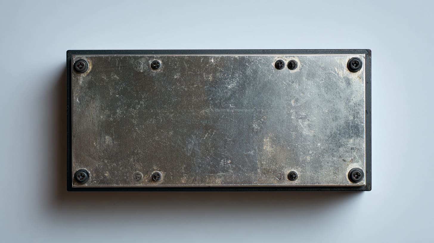
Fasteners do more than hold parts together. At enclosure seams, they also help create and maintain electrical contact.
That is why I get nervous when someone tries to cut screw count too aggressively in the name of cost, speed, or appearance. Sometimes that decision works. Sometimes it quietly weakens the shield.
Fastener spacing and distribution
If fasteners are placed too far apart, the seam can bow or lift between them. The enclosure still looks assembled, but the pressure along the seam is no longer uniform.
This is especially risky on:
- Long enclosure edges
- Thin sheet metal panels
- Large removable covers
- Areas near connectors or cutouts
A seam supported only at a few points is asking the material to behave perfectly between those points. Real materials rarely do that.
| Fastener layout | Mechanical effect | EMI effect |
|---|---|---|
| Dense and even spacing | More uniform pressure | Better seam continuity |
| Wide spacing | Mid-span lift risk | More leakage chances |
| Fasteners only at corners | Easy assembly, weak control | Poor seam performance in long edges |
I do not choose fastener count by appearance first. I choose it by where the seam is most likely to lose pressure.
Weak structural rigidity
Even with enough fasteners, weak structure can still hurt seam quality. Thin covers flex. Long panels bend. Thermal changes pull parts slightly out of shape. Vibration adds another layer over time.
This is not always visible right away. That is what makes it dangerous. A seam may perform well when the product is new and still degrade later.
I have seen enclosure lids that looked fine during early assembly but started showing weak contact after repeated opening, shipping stress, or use in harsher environments.
Incorrect screw torque
Torque matters because both extremes can cause trouble.
- Too low: not enough contact pressure
- Too high: distortion, thread damage, local bending, stripped hardware
That is why I dislike vague assembly instructions like “tighten firmly.” Real production needs more control than that.
| Torque condition | Common result | Long-term risk |
|---|---|---|
| Under-tightened | Weak seam pressure | Early leakage and loosening |
| Over-tightened | Local deformation | Reduced flatness and durability |
| Controlled torque | Stable assembly | Better repeatability |
From my point of view, a seam is only as good as the structure that keeps it closed after the first week, the first shipment, and the first few service cycles.
At this point, some teams ask a fair question: what if metal-to-metal contact alone is not enough? In many cases, that is exactly the right question.
Lack of Conductive Gaskets or Shielding Aids
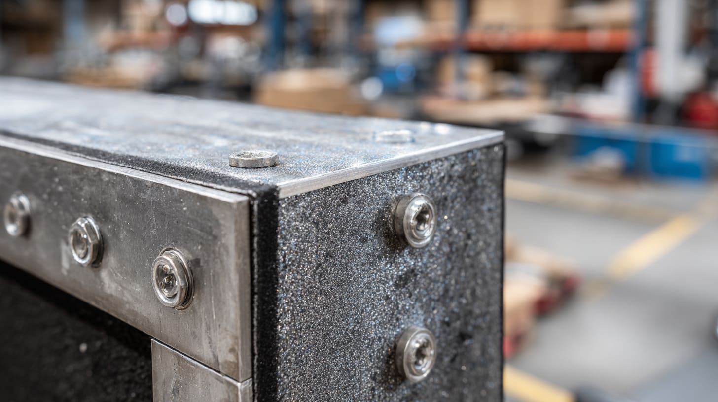
Some seam designs can work with direct metal contact alone. Others really should not rely on that approach.
I think one of the most common mistakes in enclosure work is forcing a simple seam strategy onto a project that clearly needs extra help. Pride sometimes gets in the way here. Teams want the metal parts alone to solve everything. But some designs need conductive gaskets or other shielding aids to be reliable.
When metal contact alone is not enough
Direct metal contact becomes less dependable when:
- Surface finish blocks conductivity
- Tolerance variation is hard to control
- The enclosure is opened for service
- Vibration is expected
- Frequency is high
- Large seam lengths are involved
I tend to move toward gaskets when I see several small risks stacking up, even if each risk looks manageable alone.
That is not overdesign. That is respecting how failures actually happen.
Types of EMI gaskets
There are several common gasket options, and each has its place.
| Gasket type | Strength | Typical use |
|---|---|---|
| Conductive foam | Good compliance, easy fit | Light compression designs |
| Finger stock | Strong spring contact | Repeated access covers |
| Mesh gasket | Good EMI performance | More demanding shielding cases |
| Conductive elastomer | Sealing + EMI in some uses | Harsh environments |
I do not think there is one “best” gasket for all cases. I think the right choice depends on compression range, service life, frequency concerns, corrosion environment, and assembly style.
Installation and design mistakes
A gasket is not magic. It can fail too.
Common problems include:
- Wrong compression level
- Poor groove design
- Gaps at corners
- Uneven mating pressure
- Wrong material for environment
- Damage during repeated opening
What I watch closely is whether the gasket is being treated like a real engineered component or like a soft patch for a weak design.
| Gasket mistake | What often happens |
|---|---|
| Too little compression | Weak contact and poor shielding |
| Too much compression | Material damage and shorter life |
| Bad corner treatment | Local seam leakage |
| Mixed metals without care | Corrosion risk over time |
I have seen many gasket choices made too late, after the mechanical design was already frozen. That usually leads to compromise.
And even when the gasket choice is good, frequency still changes the whole picture. What seems acceptable at one frequency may become a problem at another.
Frequency-Dependent Behavior of Seam Leakage

Frequency changes everything in EMI work. A seam that behaves quietly at lower frequencies can become much more sensitive as frequency rises.
This is where many practical misunderstandings begin. A team sees no obvious issue in a simple bench setup and assumes the seam is safe. Later, high-frequency testing tells a different story.
Why high-frequency EMI is more sensitive
At higher frequencies, wavelengths get shorter. Coupling behavior changes. Small openings start to matter more. Small discontinuities become more active.
That is why the phrase “the gap is tiny” does not comfort me much when the product has fast edges, clocks, wireless functions, or other high-frequency content.
A gap is never judged in isolation. It is judged against the electrical behavior around it.
Slot antenna effect at seams
A narrow seam opening can behave like a slot antenna. The seam becomes a path for radiation. The longer and more continuous that slot is, the more attention it deserves.
This is not just a theory issue. In real enclosure work, long seams around removable lids are often among the first places I question when EMI results look suspicious.
| Seam feature | Higher-frequency concern |
|---|---|
| Long narrow opening | Stronger slot behavior |
| Gap near noisy circuit area | Higher local leakage risk |
| Intermittent contact | Unstable performance across band |
Sometimes a product passes one test setup and struggles in another because the seam is interacting with frequency and layout in a more complex way than expected.
Testing vs real-world performance
Lab testing is necessary, but it is not the whole story. Field conditions add vibration, thermal change, cable movement, grounding differences, and user handling. A seam that barely passes in the lab may not be robust enough in actual use.
I get uneasy when a seam design passes only under ideal sample conditions. To me, that means the design may be compliant today but fragile tomorrow.
That is why I prefer margin, not just survival.
Once frequency enters the picture, long-term conditions matter even more. A seam does not live in a frozen test chamber forever. It lives in humidity, movement, and time.
Environmental and Long-Term Factors

A seam can start strong and still become weak later. That is one of the most important truths in enclosure design.
I think people often judge seams too early. They inspect a fresh build, see decent contact, and move on. But products are not built to impress only on day one. They have to keep working after shipping, storage, use, and environmental exposure.
Corrosion and humidity effects
Humidity can change contact behavior over time. Corrosion products can build up. Mixed materials can create additional trouble. Surface conditions that seemed stable at assembly may become less conductive later.
This matters even more when enclosures are used in industrial, outdoor, or semi-harsh environments.
| Environmental factor | What it can do to the seam |
|---|---|
| Humidity | Promotes corrosion and contact degradation |
| Salt exposure | Speeds up surface damage |
| Polluted air | Adds contamination and instability |
| Poor material pairing | Raises galvanic corrosion risk |
I never like seam designs that depend on a clean indoor life when the product will clearly face something rougher.
Vibration and mechanical wear
Vibration can loosen fasteners, create micro-movement, and wear down contact areas in unpredictable ways. Even a very small shift repeated many times can change the seam’s electrical behavior.
This becomes critical in:
- Transported equipment
- Mobile systems
- Industrial machines
- Equipment with fans or moving parts
Thermal cycling
Heat and cold make materials expand and contract. Different parts may move differently. Pressure can change across the seam. Over time, repeated cycling can reduce contact stability.
This is one of those risks that hides behind perfectly acceptable early samples. The first build may look excellent. The longer story may be less friendly.
| Long-term factor | Early appearance | Later effect |
|---|---|---|
| Corrosion | Invisible at first | Higher resistance |
| Vibration | Assembly still looks fine | Looser contact zones |
| Thermal cycling | No obvious issue on day one | Gradual seam instability |
When I review a seam, I try to imagine how it will behave after months, not just after assembly. That habit has saved people from a few expensive surprises.
And speaking of surprises, some of them are self-inflicted. Engineers make certain seam mistakes again and again, even when the parts look professionally designed.
Common Design Mistakes Engineers Make
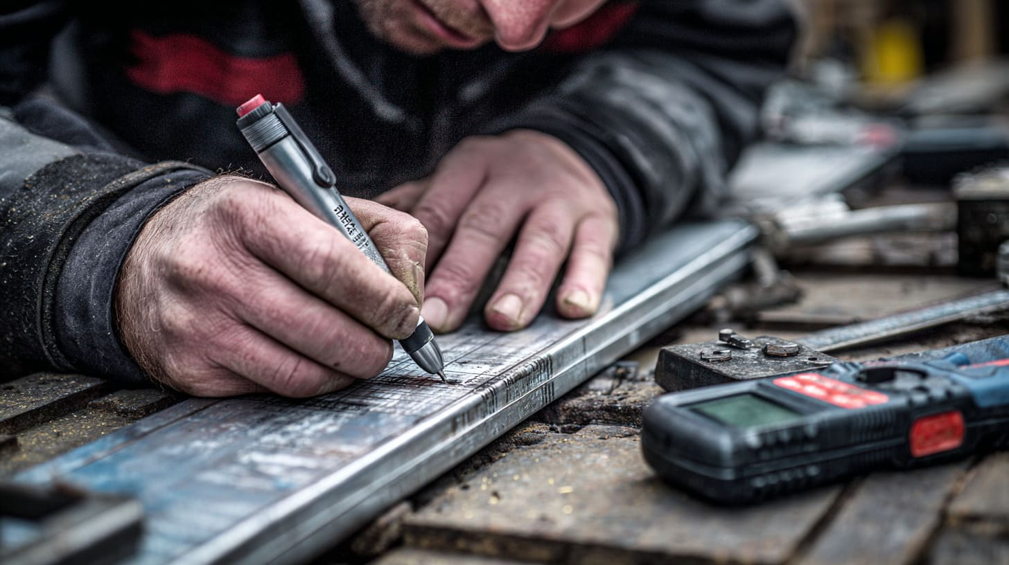
I say this with respect, because I have made some of these mistakes myself. EMI seam issues are not always caused by bad engineering. They are often caused by reasonable assumptions that were never challenged hard enough.
Over-reliance on visual quality
A seam can look tight and still be weak electrically. That may be the most common misunderstanding of all.
I have watched teams admire machining quality, coating consistency, and clean assembly lines while the actual conductive path remained uncertain. Visual quality matters, but it is not proof of EMI performance.
The most dangerous seam is often the one that looks trustworthy.
Ignoring coating impact during design phase
This mistake shows up a lot in projects where cosmetics and branding move faster than EMC thinking. The finish gets approved early. The contact path gets questioned late.
That timing hurts.
Once the design is already coated, branded, and tooled, late fixes become messy. People start scraping surfaces, adding extra hardware, or forcing gasket solutions into spaces that were not designed for them.
I get wary any time finish selection is finalized before someone clearly defines the conductive contact zones.
Lack of EMC-focused design reviews
Many design reviews are strong on dimensions, fit, appearance, and cost. That is normal. But EMI seam behavior deserves its own attention. If no one asks the right questions early, the seam becomes a hidden weakness.
Useful review questions include:
- Where is the intended conductive path at the seam?
- What finish sits in that contact area?
- How is pressure distributed?
- What happens after tolerance stack-up?
- What changes after repeated opening?
- What is the highest-risk frequency range?
| Design mistake | Why it happens | Cost later |
|---|---|---|
| Trusting visual fit | Easy to see, easy to believe | Hidden EMI failure |
| Finishing without masking plan | Cosmetics move first | Rework and redesign |
| No EMI-focused seam review | Responsibility is unclear | Delayed discovery |
Mistakes like these are common, but that does not mean the fix is mysterious. There are practical ways to reduce seam leakage if the team is willing to think early and honestly.
So let me move from failure to solution.
Practical Solutions to Reduce EMI Leakage
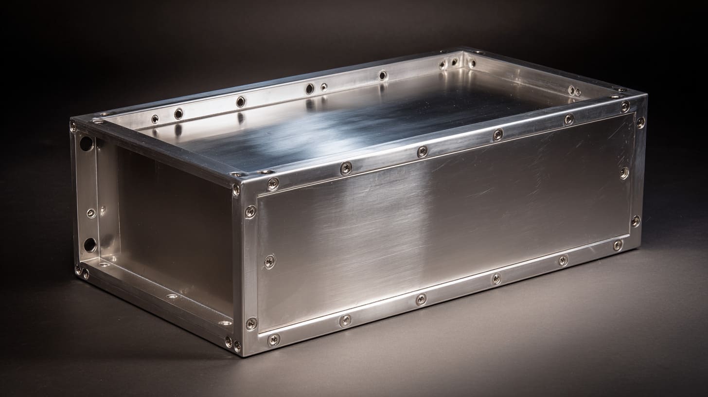
I like practical fixes more than elegant theory. In custom enclosure work, a solution has to survive manufacturing, not just sound smart in a meeting.
The good news is that seam leakage can often be reduced with disciplined design choices. The bad news is that there is rarely one single fix. Most good results come from several smaller decisions working together.
Designing for continuous conductivity
The first goal is simple: create a real conductive path and protect it from being lost.
That often means:
- Leaving bare metal contact zones
- Defining clear seam contact surfaces
- Avoiding unnecessary finish in critical areas
- Adding more than one contact path where possible
I trust seam designs more when the electrical path is obvious on the drawing, not left to assembly luck.
Improving mechanical design
Mechanical design supports electrical performance. Better fastener layout, stronger flanges, more stable alignment, and tighter tolerance control all help.
Here are some practical design moves I like:
| Design improvement | Why it helps |
|---|---|
| More even fastener spacing | Improves seam pressure consistency |
| Alignment tabs or pins | Reduces assembly shift |
| Stiffer lid or flange | Limits flex and lift |
| Better tolerance planning | Improves repeatability across batches |
I do not try to make every enclosure “perfect.” I try to make it predictable. Predictability matters more in real production.
Using shielding enhancements
When direct seam design is not enough, shielding aids can make a big difference. Conductive gaskets, finger stock, and hybrid seam designs often improve robustness.
This is especially useful when:
- The lid must be removable
- The finish must stay cosmetic
- The environment is demanding
- Frequency sensitivity is high
Validation and testing strategies
Testing should happen early enough to help, not so late that it only punishes the schedule.
I prefer this basic sequence:
- Review seam risk during design
- Build prototypes with real finishes
- Check contact strategy physically
- Run pre-compliance testing
- Adjust before mass production
| Validation step | Purpose |
|---|---|
| Prototype with production-like finish | Exposes real seam behavior |
| Pre-compliance test | Finds issues before full certification |
| Mechanical inspection of contact areas | Confirms design intent survived manufacturing |
| Iteration before tooling lock | Saves money later |
The choice I respect most is not the cheapest first design. It is the design that avoids costly surprises later.
And this is where the topic stops being only technical. Because for B2B buyers, OEM clients, and ODM projects, seam leakage affects much more than test data.
It affects trust, cost, and delivery.
How This Impacts B2B Buyers and OEM Projects
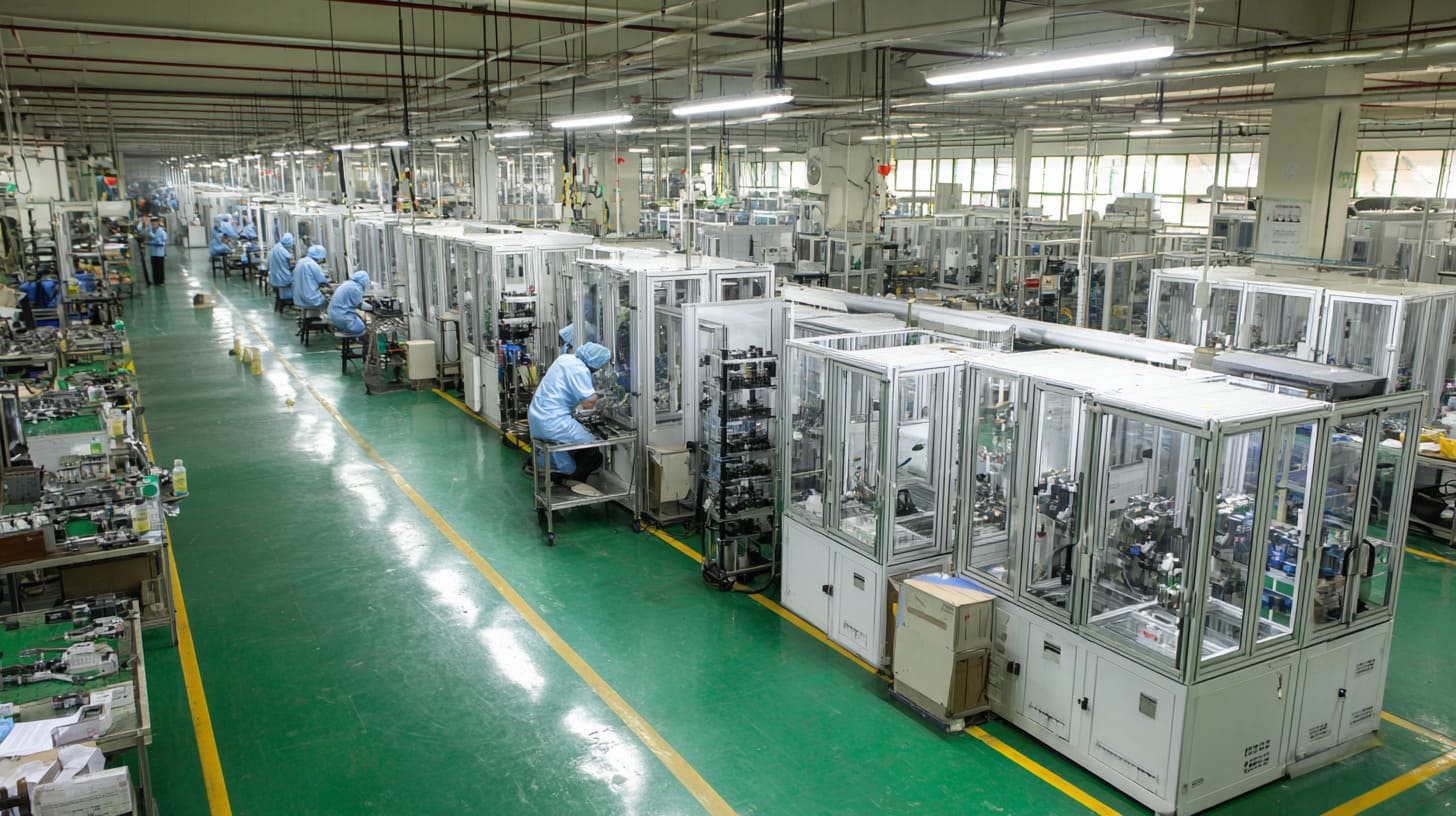
For B2B buyers, EMI leakage at enclosure seams is rarely just an engineering headache. It can turn into a business problem very quickly.
I work with customers who need custom aluminum enclosures for branded products, industrial devices, and new project launches. They are not only buying metal parts. They are buying timing, reliability, and fewer unpleasant surprises.
Cost implications of EMI failures
A seam-related EMI failure can create a chain reaction:
- Extra prototype rounds
- New finish adjustments
- Tool changes
- More assembly instructions
- Delayed certification
- Delayed shipment
- Strained supplier communication
| Failure type | Direct cost | Hidden cost |
|---|---|---|
| EMC test failure | Retest fees, redesign work | Lost project time |
| Finish rework | Extra processing, scrap risk | Delayed delivery |
| Tooling update | Engineering and machining cost | Buyer frustration |
| Late discovery | Emergency fixes | Lower confidence in supplier |
I look at seam risk partly as a cost-control issue. A small design decision early can prevent a much bigger cost later.
Supplier selection considerations
This is why supplier choice matters. A factory that only follows drawings without asking seam-related questions may still build exactly what was ordered and still help create a problem.
I think the best supplier support in this area includes:
- Asking about EMC needs early
- Flagging risky finishes
- Reviewing seam structure honestly
- Suggesting masking or gasket strategies
- Communicating clearly about production limits
A good enclosure supplier does not only quote the part. They help reduce avoidable mistakes.
What to ask your enclosure manufacturer
If I were buying a custom enclosure from a new supplier, I would ask very direct questions.
Questions worth asking
- Which seam contact areas stay conductive after finishing?
- Do you recommend masking for EMI-critical seams?
- How do you control tolerance at the mating surfaces?
- What fastener layout do you suggest for seam pressure?
- Have you worked on EMI-sensitive enclosure projects before?
- Can you support pre-compliance prototype builds?
Here is a simple buyer checklist:
| Question | Why it matters |
|---|---|
| What finish is used at the seam? | Finish may block conductivity |
| How is seam pressure maintained? | Weak pressure means weak contact |
| Are conductive gaskets needed? | Some designs need more than bare metal |
| Can you support design review? | Early advice reduces risk |
| Can you keep delivery stable after changes? | Late EMI fixes often pressure the schedule |
From a buyer’s side, I would rather have one honest conversation early than five tense ones after a failed test.
That brings me to the last point, because this whole topic looks small until it costs real time and money.
Conclusion
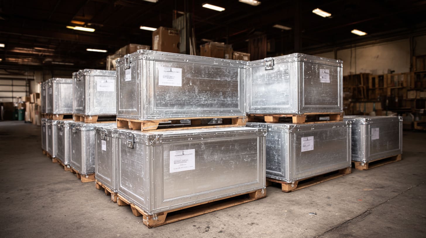
EMI leakage at enclosure seams is rarely caused by one dramatic mistake. Most of the time, it comes from smaller things that seem harmless when viewed alone. A coating here. A gap there. A little less pressure than expected. A seam that looks good but is not truly continuous.
That is why I never treat seam design like a side issue.
A reliable enclosure needs both mechanical thinking and electrical thinking. It needs good contact, sensible finishes, stable structure, controlled tolerances, and a realistic view of what happens after the first assembly. It also needs honesty. Some seam strategies are strong enough on their own. Some are not. Pretending they are the same only makes the project harder later.
If you are a buyer, engineer, or brand owner working on a custom aluminum enclosure, I think it is worth asking seam questions earlier than feels necessary. That early attention can save cost, testing trouble, and delays later.
If you want to discuss a custom enclosure project with EMI concerns, I am happy to look at the design direction with you and help judge the seam risks before they turn into expensive fixes.