Skip to content

On most factory visits, I hear the same quiet question after the tour of robots, drives, and cables: “So… what is actually controlling all of this?” Very often, the answer is one small box on a DIN rail: the PLC.
A PLC (Programmable Logic Controller) is the person in the control room, but in electronic form. It watches sensors, runs logic, and drives outputs. It decides when a motor should start, when a valve should close, and when an alarm should shout at everyone in the room.
For me, the real value of a PLC shows up when something stops in the middle of a shift and everybody turns to the control cabinet, not the machine brochure, to find out what went wrong.
In my work at MaidaTech, I meet different kinds of customers. Davide from Finland wants stable OEM enclosures for his PLC-based systems. John from Hungary wants to use a Pi-style board with PLC-like control ideas. Jackson from Belgium cares about how the enclosure and PLC work together, because he has to sell and service the final product.
In this guide, I want to walk with you step by step:
- What a PLC is in electrical engineering
- How it works inside
- What types exist and when to use which
- How PLCs talk to other devices
- How to pick, protect, and maintain them
- And where custom enclosures really make a difference
Once you see a PLC as a “thinking hub” with real limits and trade-offs, it becomes easier to choose it, program it, and design the right box around it.
Before we dive into wiring, brands, and protocols, we should first agree on what a PLC is in the language of electrical engineering.
What Is a PLC in Electrical Engineering?

When someone asks me “What is a PLC?” I adjust my answer based on how many headaches they already had with control panels and relays.
What does PLC stand for?
PLC stands for Programmable Logic Controller.
- Programmable – you can change the logic with software instead of rewiring.
- Logic – it makes decisions based on rules (conditions, timers, counters).
- Controller – it sends commands to devices like motors, valves, and lights.
Basic definition and core function
In simple terms:
A PLC is an industrial computer that reads inputs, runs logic, and controls outputs in real time.
Typical inputs:
- Push buttons
- Limit switches
- Proximity sensors
- Temperature or pressure sensors
Typical outputs:
- Contactors and relays
- Solenoid valves
- Indicator lights
- Speed control signals for drives
A PLC is built to survive noise, vibration, and heat in places where a normal office PC would die quickly.
PLC vs traditional relay-based systems
When I started working with older factories, I saw panels full of relays. If you wanted to add one simple delay function, you needed a timer relay, extra wires, and space.
With PLCs, you replace many relays with software logic. Instead of rewiring, you update a program.
Here is a simple comparison:
| Aspect | Relay-Based System | PLC-Based System |
|---|---|---|
| Logic change | Rewire physically | Edit software |
| Panel space | Many relays, bulky | Fewer components, more compact |
| Diagnostics | Manual checking, hard to trace | Status bits, error flags, monitoring via HMI |
| Flexibility | Low | High |
| Complexity limit | Becomes messy quickly | Scales better |
Why PLCs replaced relay logic
Relays still exist, but PLCs took over the “brain” role in most modern systems because:
- Changes are faster and cheaper
- Complex logic is easier to manage
- Diagnostics are much clearer
- Integration with networks, HMIs, and SCADA is simpler
From my side, whenever I see a panel still 100% relay-based, I ask how often they need to change the process. If they say “every few months,” a PLC almost always makes more long-term sense.
When this basic picture of “PLCs vs relays” is clear, it becomes easier to understand how a PLC actually works on the inside.
How Does a PLC Work?
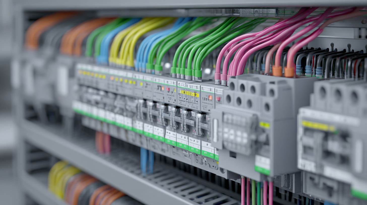
When I sit with a new engineer, I often ask them to trace one signal: from a sensor, through the PLC, to a motor. If they can explain that path clearly, I know they understand the real behavior of the system.
Key components inside a PLC
A PLC is not magic. It is built from a few clear blocks.
| Component | Role in the PLC system |
|---|---|
| Power supply | Feeds the PLC electronics (often 24 VDC or 230 VAC input) |
| CPU | Runs the logic; it is the “brain” |
| Memory | Stores the program, parameters, and data |
| Input modules | Read signals from sensors and switches |
| Output modules | Drive relays, valves, contactors, or analog signals |
| Communication ports | Connect to HMIs, SCADA, drives, or other PLCs |
Power supply
The power supply stabilizes voltage. If it is weak or poorly selected, the smartest PLC will reset at the worst possible moment.
CPU and memory
The CPU executes the user program again and again. Memory holds:
- Logic (the program itself)
- Parameters (setpoints, timers, config)
- Status data (fault codes, counters)
I/O modules
Input and output modules form the “hands and eyes” of the PLC:
- Digital inputs – ON/OFF signals (buttons, switches)
- Analog inputs – values with ranges (4–20 mA, 0–10 V)
- Digital outputs – ON/OFF commands to devices
- Analog outputs – control signals to drives or valves
Basic operation cycle (Scan Cycle: Input → Process → Output)
A PLC works in a loop called the scan cycle:
- Read inputs
- Execute program logic
- Update outputs
- Perform diagnostics / communication
- Repeat
This happens many times per second.
A simple way to see it:
| Step | What happens | Example |
|---|---|---|
| Read | PLC checks sensor states | Button pressed, sensor ON |
| Process | PLC runs logic based on ladder or FBD | If sensor ON, start motor after 5 sec |
| Write | PLC updates outputs | Motor output ON |
| Communicate | PLC shares data with HMI or SCADA | Show status on touch screen |
Simple diagram example (sensor to motor)
A very basic case:
- Sensor detects part in position → Input I0.0 = ON
- PLC logic says: if I0.0 = ON and safety OK, then set Q0.0 = ON
- Q0.0 drives a contactor → motor runs
On real projects, I often judge if a PLC design is healthy by how quickly I can follow this chain from input to logic to output without getting lost in “temporary patches” inside the program.
Once you understand this loop, the question naturally becomes: why go through all this trouble instead of using simple hard-wired controls?
Why Use a PLC in Industrial Applications?

When a buyer tells me, “Can we just make it simpler and skip the PLC?” I do not answer yes or no right away; I first look at how often they change their process and how much downtime costs them.
Advantages of using PLCs
Key advantages:
- Reliability – built for harsh environments
- Flexibility – easy to update logic
- Real-time processing – fast and predictable response
- Compact size – high function in small space
- Life cycle – long support, spare parts, documentation
Here is a compact view:
| Advantage | What it means in real life |
|---|---|
| Reliability | Fewer field failures, fewer emergency visits |
| Flexibility | Quick changes when process or product changes |
| Real-time | Stable cycle time, predictable response to signals |
| Compact size | Smaller cabinet, easier layout |
| Long life cycle | Support for many years, easier standardization |
Use cases in different industries
Manufacturing
- Assembly lines
- Packaging machines
- Conveyor systems
Here, PLCs handle interlocks, safety signals (with proper safety devices), and coordination between many small actions.
Energy
- Pump stations
- Small substations
- Solar or wind system control
PLCs monitor flow, voltage, pressure, and help automate start/stop sequences.
Automotive
- Body assembly
- Painting lines
- Testing stations
These lines change often. Software-based control makes changes manageable.
OEM equipment control
This is where many of my customers live. They design machines or control boxes, then ship them to their own clients.
A typical OEM flow:
- End user shares process idea with OEM
- OEM decides on PLC brand and logic concept
- OEM asks a factory like ours to design and build the enclosure
- System gets branded with OEM logo and delivered as a complete product
From my own experience, the main reason I push PLCs is not “technology coolness” but predictable behavior over years, even when operators, products, or small details in the process keep changing.
After you see why PLCs are worth using, the next question is: which type of PLC should you pick?
Types of PLCs Explained
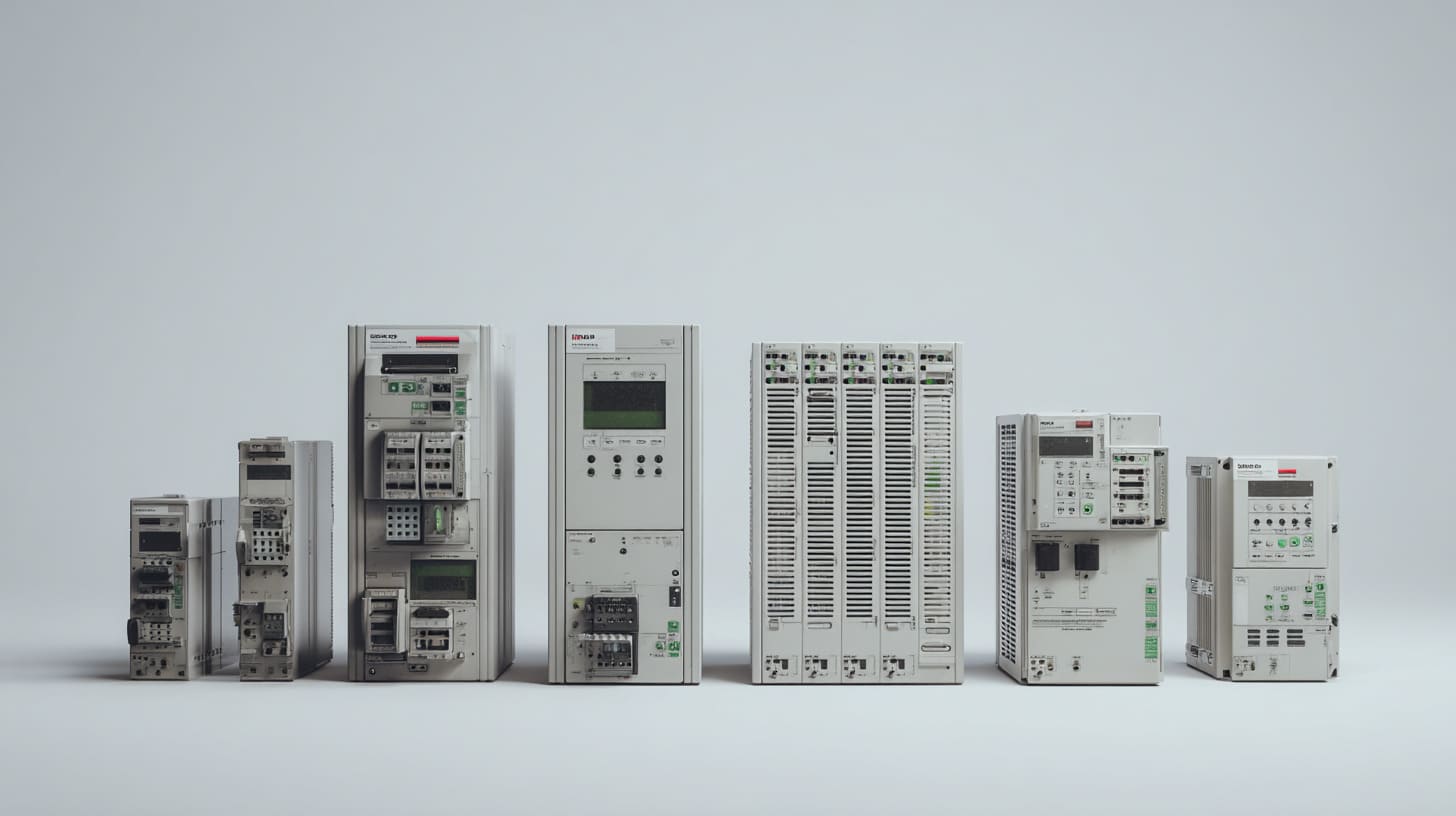
The hardest selection calls are not about “PLC or no PLC,” but about choosing between five models that all look almost right on paper.
Based on size and configuration
We can group PLCs by size and structure.
| Type | Typical I/O size | Structure | Typical use |
|---|---|---|---|
| Nano PLC | Very small | All-in-one | Tiny machines, simple control |
| Micro PLC | Small to medium | All-in-one + small expansion | Small machines, basic automation |
| Modular PLC | Medium to large | CPU + I/O modules | Lines, cells, multi-zone control |
| Rack-mounted | Large | Backplane + modules | Complex plants and systems |
Nano PLC
Good for:
- Simple pump control
- One small machine with a few I/Os
- Low budget but still needs programmability
Micro PLC
Good for:
- Small machines with more steps
- Projects that need a bit of expansion later
Modular PLC
This is the “workhorse” in many factories:
- Flexible I/O mix
- Easy to expand
- Often strong communication options
Rack-mounted PLC
Used in:
- Large plants
- Power generation
- Complex chemical processes
Based on programming and control capability
| Type | Key idea | Typical role |
|---|---|---|
| Compact PLC | All-in-one package, limited expansion | Small to mid-size machines |
| Distributed PLC | Control spread across several stations | Large lines, distributed I/O |
| Safety PLC | Designed for safety functions (SIL/PL) | Safety-critical control (E-stop logic) |
In many projects, I tend to shortlist PLC types based on I/O growth and the skill level of technicians who will maintain them, long before I worry about rare advanced options hidden deep in the datasheet.
Once you have a rough sense of type and size, you can start thinking about the part that many engineers enjoy the most: the programming.
PLC Programming Basics

When I review a project, I often find that the hardware is fine, but the real problems live inside the program—especially when three different people “patched” it over several years.
Common PLC programming languages
The most common languages follow IEC 61131-3.
| Language | Style | When I see it used most |
|---|---|---|
| Ladder Logic (LD) | Looks like relay circuits | Classic machine control, electricians’ favorite |
| Function Block (FBD) | Blocks with signals between | Analog control, process logic |
| Structured Text (ST) | Text, similar to coding | Complex calculations, data handling |
| Sequential Function (SFC) | Steps and transitions | Multi-step sequences, batch processes |
Ladder Logic (LD)
- Visual
- Easy for technicians used to relays
- Great for simple and medium logic
Function Block Diagram (FBD)
- Good for PID loops, scaling, math
- Clear visual flow
Structured Text (ST)
- Powerful for complex math, string handling, protocols
- Needs more coding discipline
Sequential Function Chart (SFC)
- Breaks the process into steps and transitions
- Helps visualize what should happen when
Typical development tools & software
Different brands, different tools:
- Siemens – TIA Portal
- Allen-Bradley – Studio 5000 / RSLogix
- Mitsubishi – GX Works
- Schneider – EcoStruxure Control Expert
Each has its own license model, learning curve, and ecosystem.
Basic example of a ladder diagram
A simple motor start with interlock:
- Start button and safety OK → coil for motor ON
- Stop button breaks the circuit
If you show this in ladder to a technician, they often understand it faster than any text.
During program reviews, I pay the most attention to how the logic is structured rather than which language is used, because messy logic with no comments usually costs more time than any difference between CPUs or brands.
After the logic language is clear, the next practical question from most buyers is: “Which brand should we standardize on?”
Common PLC Brands and Their Ecosystems

Brand choice is not only about specs. It also decides who can support the system, how easy it is to get spare parts, and how your customers feel when they see the name on the door of the panel.
Major global PLC suppliers
Some of the well-known brands:
| Brand | Strong regions / reputation |
|---|---|
| Siemens | Europe, global OEM and plant standard |
| Allen-Bradley | North America, heavy industry |
| Mitsubishi | Asia, packaging, machine builders |
| Schneider Electric | Global, power + automation |
| Omron | Japan, sensors + PLC integration |
| Delta, others | Cost-effective options, strong in Asia |
Each comes with:
- Its own programming software
- Its own module range
- Different license and support policies
Compatibility and ecosystem considerations
When I help a buyer think through brand choice, we look at:
- Existing standards in their plants or region
- Local support and spare part availability
- Software license cost and training effort
- Integration with drives, HMIs, and other devices
A simple table I use often:
| Question | Why it matters |
|---|---|
| Can your local team program this PLC? | Reduces dependency on one external expert |
| Can you buy spare parts locally? | Cuts downtime during faults |
| Does it match your drives / HMIs? | Reduces integration pain |
| Is the license model sustainable? | Avoids surprises in future projects |
My first filter between PLC brands is almost never the fancy brochure; it is whether my customer can get fast support, modules, and licenses in the markets where they actually ship their machines.
Once the brand and platform are clear, it becomes easier to talk about what we actually do with PLCs in real applications.
Typical Applications and Use Cases

Whenever I map a PLC project, I try to picture the person standing next to the machine at 3 p.m. on a busy day, not the perfect demo on day one.
PLCs in automated production lines
Common functions:
- Start/stop sequences
- Interlocks between machines
- Buffer control between conveyors
- Alarm handling and fault recovery
In one line I worked on, a single PLC coordinated five small machines. The logic did not make the line faster, but it made the behavior more predictable during jams.
Integration with sensors, HMIs, and SCADA
PLCs rarely work alone.
- Sensors feed real-world conditions
- HMI (Human Machine Interface) gives operators buttons and screens
- SCADA or MES systems collect data and send commands
A simple structure:
| Layer | Role |
|---|---|
| Sensors / Actuators | Real-world interaction |
| PLC | Central logic and control |
| HMI | Local operation and status |
| SCADA / MES | Supervisory control and data logging |
Use in HVAC, energy systems, and transport
- HVAC: control fans, valves, dampers, temperature loops
- Energy: switchgear control, generator start/stop
- Transport: conveyors in airports, baggage handling, small lift systems
Examples from OEM/ODM equipment applications
For my OEM clients:
- Davide might ask us to build an aluminum enclosure for a compact PLC controlling a test bench.
- John might design a board that behaves like a small PLC and needs a custom case with correct cutouts and airflow.
- Jackson might re-brand a machine that uses a well-known PLC and wants the enclosure and labels to fit his local market.
When I judge a new PLC application, I think about who must live with the system every single day—operator, technician, or service engineer—because they will decide if the design was smart or just clever on paper.
As soon as we connect more devices, one big topic comes up again and again: communication.
PLC Communication and Networking

I have seen beautiful network diagrams fail in the real world simply because nobody asked, “What happens if this one cable breaks?”
Common PLC communication protocols
Some of the most common ones:
| Protocol | Type | Typical use |
|---|---|---|
| Modbus (RTU/TCP) | Open, simple | Linking PLCs, meters, small devices |
| Profibus | Fieldbus | Older Siemens networks, many devices |
| Profinet | Industrial Ethernet | Modern Siemens networks, real-time control |
| Ethernet/IP | Industrial Ethernet | Allen-Bradley ecosystems |
| CANopen | Fieldbus | Motion, distributed I/O |
Each protocol has:
- Physical layer (cable type)
- Speed limits
- Device count and topology rules
PLC and HMI communication
Typical setups:
- HMI directly connected to PLC via Ethernet
- Several HMIs to one PLC
- PLCs providing tags to SCADA and HMIs at the same time
Key checks:
- Tag naming rules
- Update rate (how fast values refresh)
- Security (who can change what)
Integration with IoT and cloud platforms
More and more, clients ask:
- Can we log data to a cloud dashboard?
- Can we access the PLC remotely?
Typical options:
- PLC gateway device
- MQTT, OPC UA, or vendor-specific cloud connectors
- Edge devices near the PLC
When I review a PLC network, my main concern is not how “modern” the protocol is but how the system behaves when one link fails and how easy it is for on-site staff to understand what to check first.
Once communication is on the table, the next question from many engineers is very practical: “So which PLC should we choose for this project?”
How to Choose the Right PLC for Your Project

Many of my most tense email threads are not about “PLC vs no PLC,” but about choosing between two models that are both almost correct—and will both be painful if chosen for the wrong reasons.
Key selection criteria
Some core points:
- Number and type of I/Os
- Communication needs
- Environmental conditions
- Performance and response time
- Budget and long-term scalability
Here is a simple overview:
| Criterion | What to think about |
|---|---|
| I/O count & type | Digital vs analog, current needs, future expansion |
| Communication | Protocols needed now and later |
| Environment | Temperature, dust, moisture (and matching enclosure) |
| Performance | Cycle time, motion control, data handling |
| Budget & scalability | Cost now vs cost of change later |
Matching PLC to your custom enclosure
This is where my daily work comes in directly.
Sizing the case
You need to consider:
- PLC size and modules
- Extra space for future modules
- Wiring space and bending radius of cables
- Space for power supply, breakers, and terminals
Mounting options (DIN rail, panel)
Most PLCs mount on DIN rail. Some go on backplates.
- Make sure rail is long enough for expansion
- Leave finger-safe space for maintenance
- Plan access for screwdrivers and test probes
Ventilation and access for programming
With custom aluminum or plastic enclosures, we consider:
- Heat dissipation (slots, fans, or thicker walls as heat sink paths)
- Space for Ethernet/USB programming ports
- Door layout for HMI and status lights
I often choose a PLC not by the longest feature list but by the combination of acceptable performance and long-term maintainability, especially when I know that the original design engineer may not be the one doing support five years from now.
Once we have chosen the PLC and the enclosure, the next key question is how to keep the system healthy during daily operation.
PLC Maintenance and Troubleshooting

Some of the most expensive “PLC problems” I have seen had nothing to do with the PLC itself but with poor wiring, missing backups, or unclear alarms.
Common PLC faults and how to detect them
Common issues:
- Power supply failure or unstable voltage
- I/O module failure
- Loose terminals or broken field wiring
- Program corruption after unsafe changes
- Communication timeouts
How they show up:
| Symptom | Possible cause |
|---|---|
| PLC in STOP or FAULT | Internal error, program issue |
| Some devices dead, others OK | Single I/O module or fuse problem |
| Random resets | Power supply instability |
| HMI shows “no PLC” | Network or IP conflict |
Importance of diagnostics and HMI alerts
Good design includes:
- Clear alarm texts, not just codes
- Grouping alarms by area or severity
- History logs for faults
Routine maintenance checklist
A simple checklist I like to see:
| Item | Action | Frequency |
|---|---|---|
| Power supply voltage | Measure and log | Yearly or on issue |
| Terminal tightness | Check and re-tighten | Yearly |
| PLC & HMI backups | Export and store safely | After each change |
| Firmware versions | Review and update when needed | Yearly |
| Cabinet cleanliness | Remove dust, check filters | Yearly |
When downtime is painful and every minute counts, I judge a PLC setup by how quickly a tired technician at 2 a.m. can track the fault from an alarm text to the exact terminal, not by how clean the cabinet looked in the sales photo.
Once we have a stable PLC and maintenance plan, the last physical piece to consider is the enclosure and how well it supports all this effort.
Custom Enclosures for PLC Systems

I spend a lot of my day looking at the same basic question in different forms: “Can you make an enclosure that fits this PLC, all the wiring, and our logo without causing heat or access problems?”
Why enclosure quality matters
A PLC without the right enclosure is like a good driver in a car with no doors and no roof.
Key points:
- Protection against dust, moisture, and accidental contact
- Mechanical support and safe wiring layout
- Heat path and airflow
- Service access
IP rating for industrial protection
We often match IP rating to environment:
| Environment | Typical IP target |
|---|---|
| Clean control room | IP20–IP30 |
| Workshop with dust | IP54–IP55 |
| Outdoor or washdown | IP65–IP66 (and beyond) |
Heat dissipation
PLCs and modules generate heat:
- Aluminum enclosures can help act as heat spreaders
- Plastic enclosures may need vents or fans
- Layout matters: hot devices should not be boxed in tight corners
Access for I/O wiring
Small details:
- Enough space above terminals
- Room for ferrules and labels
- Cable entry positions that match real installation paths
Aluminum vs plastic PLC enclosures
I work with both aluminum and plastic. Each has its own sweet spot.
| Aspect | Aluminum enclosure | Plastic enclosure |
|---|---|---|
| Strength | High, rigid | Moderate |
| EMI shielding | Good | Weak, needs extra metal if required |
| Heat dissipation | Better (can act as heat sink) | Limited |
| Custom machining | Very flexible (CNC, punching) | Good but depends on material |
| Weight | Heavier | Lighter |
| Cost | Higher material cost, but robust feel | Often lower, good for lighter duty |
For PLC systems with sensitive signals or tougher environments, I usually lean toward aluminum enclosures with proper mounting, because the combination of rigidity, shielding, and thermal behavior saves trouble later.
OEM branding and private label options
For many of my customers, the PLC and enclosure are part of their brand story:
- Custom logo engraving or printing
- Color matching to brand palette
- Specific cutouts for their standard PLC model
- Custom labels and packaging
On the enclosure side, I tend to keep “nice-looking” features second and focus first on survival, wiring space, and thermal performance; once those are correct, we layer in branding and aesthetics in a way that does not break functionality.
After walking through PLC basics, types, communication, and enclosures, we can now step back and see why all these details matter together.
Conclusion

For me, PLCs are not just “control hardware.” They sit at the point where electrical design, process logic, human behavior, and physical protection meet. If any one of those parts is weak, the whole system feels fragile.
In this guide, I tried to explain:
- What a PLC is and how it differs from old relay logic
- How it reads inputs, runs logic, and drives outputs
- Which types of PLCs exist and how I think about them
- Why brand, ecosystem, and communication matter in real factories
- How to match a PLC to its enclosure and to the people who must live with it
- Why maintenance, backups, and clear diagnostics are not “extras” but core design choices
I talk about PLCs this way because I see the same pattern again and again with my customers from Europe, North America, Japan, and beyond: the successful projects are not the ones with the biggest CPU, but the ones where the logic, enclosure, and daily users are all aligned.
If I have to choose one rule to guide my PLC decisions, it is that control should stay understandable to the people who must fix it under pressure, not only to the person who wrote the first version of the program.
If you are planning a new PLC-based project, or you want to redesign your control enclosure for better wiring, protection, and branding, you are very welcome to share your drawings and ideas with me. I can help you think through PLC size, layout, I/O access, and custom aluminum or plastic enclosures so that your product looks clean on the outside and stays calm on the inside when the factory gets busy.
You can always reach me at info@maidatech.com or through maidatechenclosure.com. Even a simple sketch or photo is enough to start a real conversation about how to make your next PLC panel not just workable, but comfortable to live with for years.