Skip to content
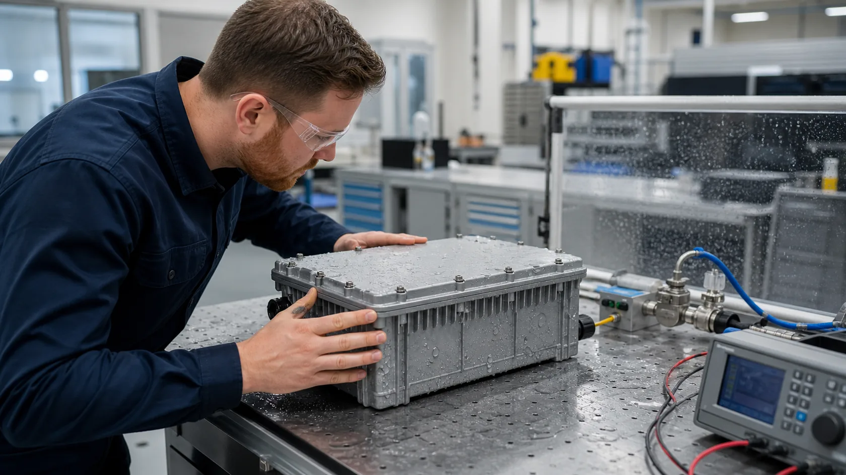
When a buyer asks us for a waterproof enclosure, the conversation often starts with an IP rating. In the factory, I start one step earlier: where can water actually travel into this particular assembly? The cover joint is only one path. Cable entries, service doors, windows, fasteners, vents, and even a poorly drained mounting position can decide whether the electronics stay dry.
That is why a gasket should not be selected from a material name alone. The seal needs the right shape, material, compression, mating surfaces, closure force, exposure, and maintenance plan. IEC 60529 provides the IP-code framework, but it does not turn a bare enclosure wall into a complete installed system.
In this guide, I explain the common seal types we see in industrial enclosures and the checks that make them useful in production.
Begin With the Whole Sealing Path
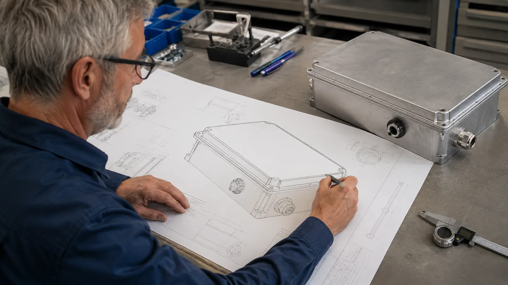
A waterproof result belongs to the complete assembly, not to a roll of gasket material. Before choosing a profile, list every joint and penetration that separates the inside from the environment.
Map the weak points before choosing a gasket
| Sealing location | Typical design question |
|---|---|
| Cover or door perimeter | Is the flange flat and stiff enough to compress the seal evenly? |
| Cable entry | Does the gland match the cable diameter, thread, washer, and tightening instruction? |
| Viewing window or display | Is the bonded or mechanically retained seal suitable for rework and exposure? |
| Vent, connector, or blanking plug | Does the accessory preserve the claimed protection in its installed orientation? |
UL Solutions notes that accessories such as cable and pipe fittings, windows, plugs, latches, and handles can be evaluated to maintain a Type or IP rating on a suitably rated enclosure. That is a good reminder that each opening needs its own design evidence.
My practical rule is simple: do not ask one cover gasket to compensate for three uncontrolled penetrations. A clear path map makes the next material and geometry choices much calmer.
Flat Sheet and Foam Gaskets
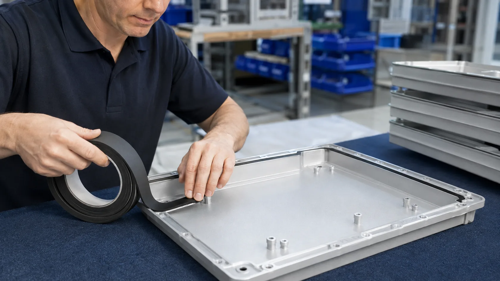
Flat gaskets are common on removable covers, doors, windows, and broad flange joints. They may be supplied as die-cut sheet, adhesive-backed strip, or a formed perimeter. Cellular foam is useful when the mating faces have modest variation and the closure is designed to compress it consistently.
Where foam works well—and where it needs care
Closed-cell foam can help block water without acting like a sponge, but it is still an engineered component. Thickness, density, compression behavior, adhesive, corner treatment, and the expected number of opening cycles all matter. A door that is opened for routine service is a different application from a permanently clamped cover.
UL 50E guidance distinguishes cellular gaskets intended for continuous compression from those evaluated for periodic recompression. For a serviceable enclosure, that distinction is worth asking about early rather than after the drawing is frozen.
I like foam gaskets for broad, low-pressure enclosure joints when the flange, screw spacing, and compression stop are controlled. I become cautious when a soft strip is expected to bridge warped sheet metal, sharp corners, coating buildup, and repeated door slams at the same time.
O-Rings and Molded Solid Gaskets
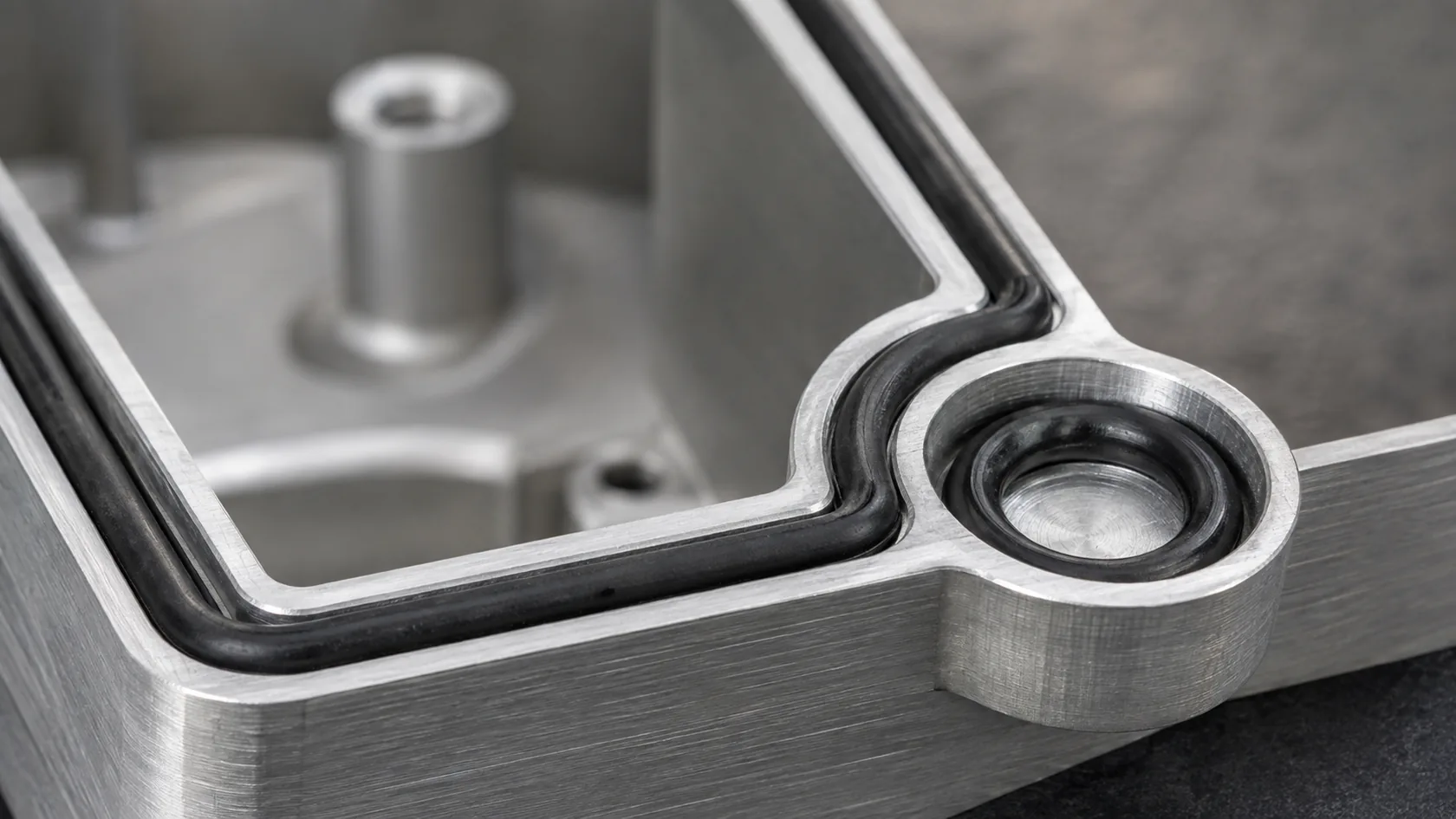
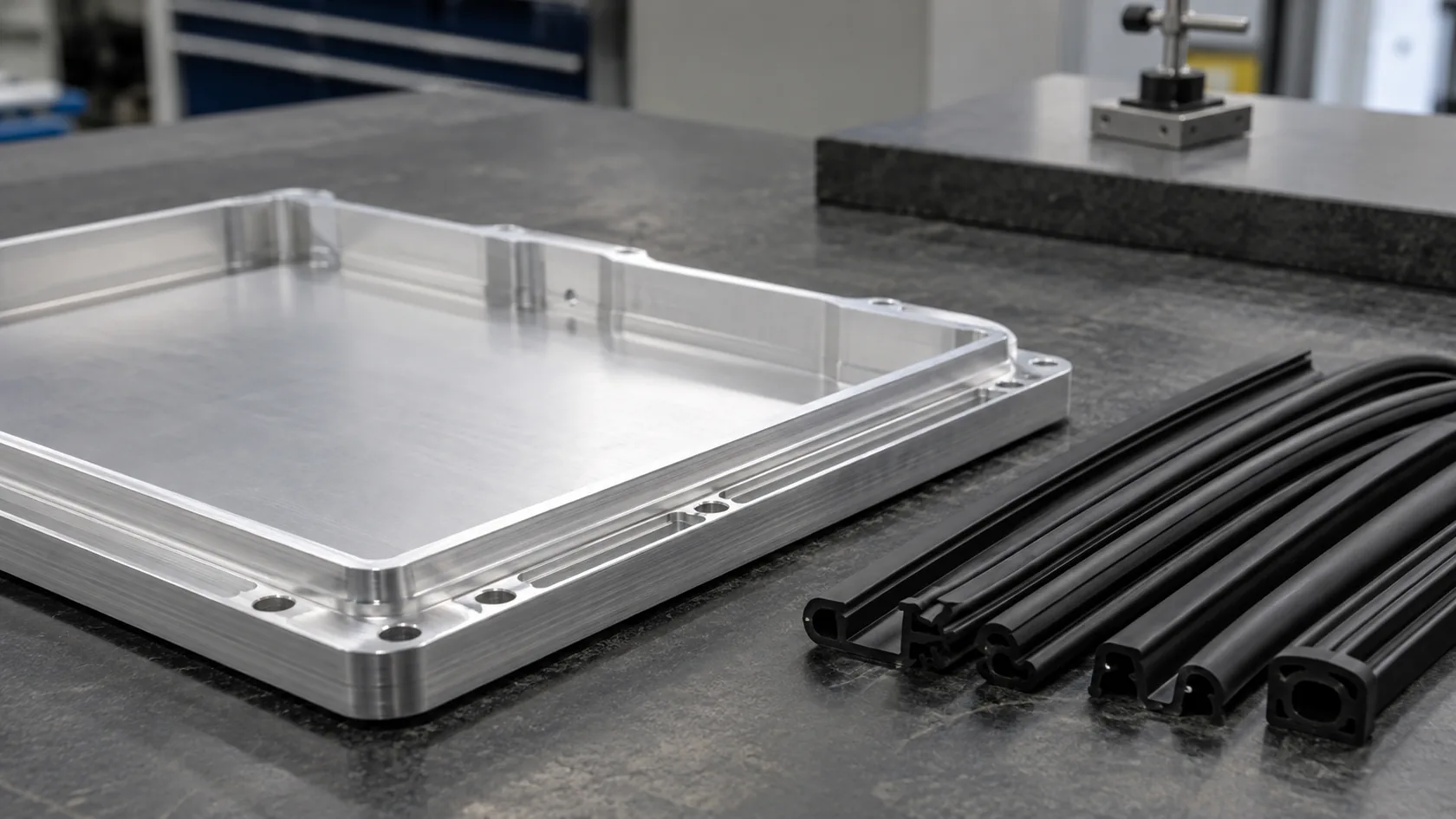
O-rings and molded solid gaskets suit more defined grooves, circular interfaces, machined covers, connectors, and higher-control enclosure joints. A molded perimeter gasket can follow complex corners and local features better than a straight strip, provided the tool, joint, and assembly method are designed together.
The groove is part of the seal
An O-ring is not a magic circle that fixes an uncertain joint. Its cross-section, gland dimensions, surface condition, squeeze, stretch where applicable, and tolerance stack determine whether it establishes a reliable seal line. Parker’s O-Ring Handbook describes compression set as a common failure mode and links reliable sealing to compound selection, gland design, proper squeeze, testing, and trained assembly.
| Seal format | Often useful for | Watch closely |
|---|---|---|
| Standard O-ring | Circular ports, plugs, connectors, defined grooves | Groove dimensions, twist, damage, chemical compatibility |
| Molded perimeter gasket | Covers with corners, bosses, or complex outlines | Tooling cost, joint design, compression uniformity |
| Solid flat gasket | Rigid, well-controlled flanges | Bolt load distribution, surface finish, rework handling |
For small sealed covers, a molded gasket and a well-supported groove can be very repeatable. But if the cover flexes between screws, the best compound on the datasheet cannot keep compression uniform. That leads naturally to material selection.
Choose the Elastomer for the Exposure
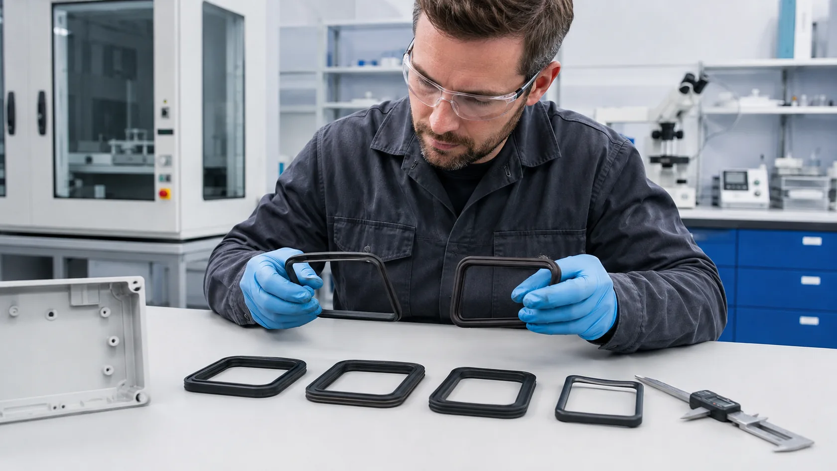
EPDM, silicone, nitrile rubber (NBR), neoprene, fluorosilicone, and other elastomers are selected for different combinations of weather, temperature, fluids, compression recovery, and manufacturing needs. There is no universal “waterproof rubber.”
Use the environment, not the color, as the starting point
| Material familyCommon enclosure reason to consider itQuestion to confirm before release | ||
|---|---|---|
| EPDM | Outdoor water and weather exposure | Temperature range, formulation, and actual chemical contact |
| Silicone | Wide temperature flexibility and soft sealing | Tear resistance, compression behavior, and exposure details |
| NBR | Applications where oil resistance may matter | Outdoor weathering and the actual fluid mix |
| Neoprene blends | General-purpose industrial sealing cases | Compound-specific weather, oil, and compression data |
These are direction-setting examples, not approval shortcuts. The same base polymer can perform differently by compound, hardness, filler system, curing, and test condition. Parker also points out that compound choice depends on pressure, temperature, and the medium being sealed, and that the final choice is often a compromise rather than a single perfect answer.
From my side of a quotation, I ask for the outdoor exposure, wash chemicals, oils or coolants, temperature cycle, service frequency, and target test basis. That short checklist is much more valuable than ordering “black EPDM” without a part specification.
Use Geometry and Closure Force to Protect Compression
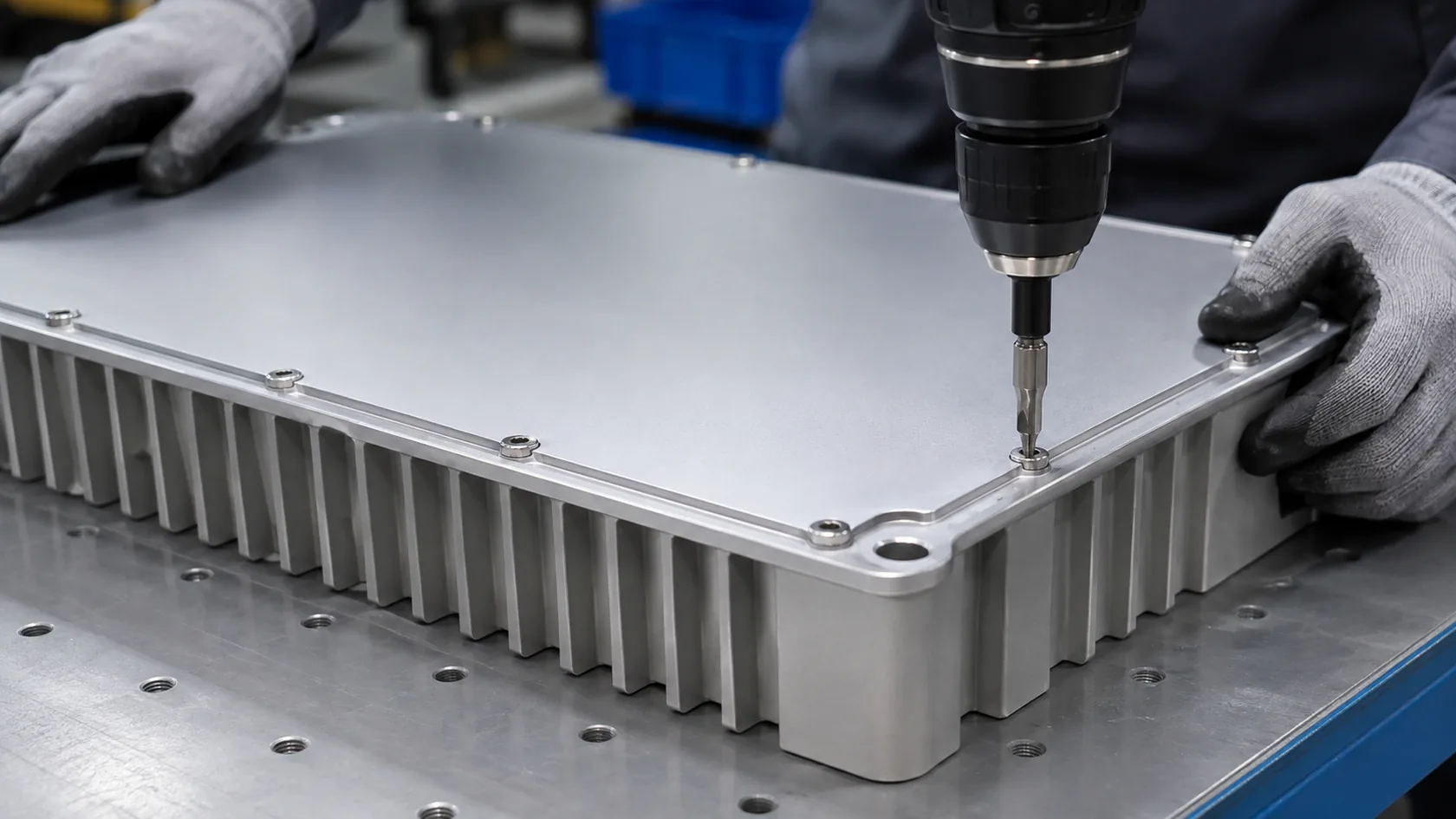
Most gasket failures we investigate are not mysterious material failures. The gasket may be pinched at a corner, stretched at an entry point, unevenly compressed by a flexible lid, or damaged when the cover slides into place. Seal geometry and closure hardware turn a material into a working system.
Design for even contact, not maximum tightening
Useful design checks include:
- Provide a continuous, clean sealing land or groove that matches the chosen profile.
- Keep corners, joints, and interrupted areas intentional; do not hide a gap beneath a latch.
- Use screw or latch spacing that limits cover deflection between closure points.
- Define assembly sequence and torque where fasteners create the clamping load.
- Consider compression stops where an over-tightened cover could crush a cellular gasket.
More tightening is not automatically safer. Excess squeeze can damage a seal or accelerate permanent deformation, while too little or uneven squeeze leaves leakage paths. If we need a very soft foam to hide a large flatness problem, I normally prefer to review the cover stiffness and manufacturing tolerances before committing to a material change.
After the cover joint is sound, the design still needs to account for water reaching the enclosure from unexpected directions.
Seal Cable Entries, Service Joints, and Outdoor Details
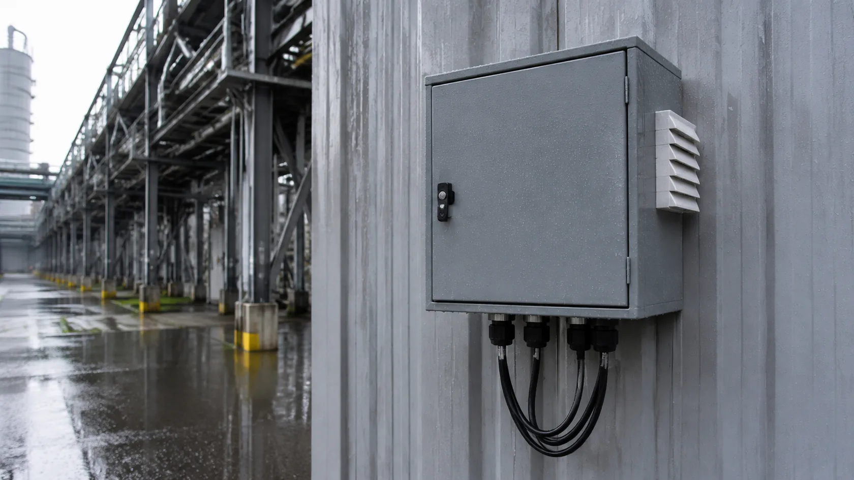
An enclosure body can pass a careful water test and still leak through a cable gland installed on the wrong cable range. The same issue appears with connector panels, removable doors, hinge lines, vents, blanking plugs, and cable routes that carry water toward the entry.
Make installation part of the design record
For an outdoor enclosure, document the approved entry parts, hole size, cable range, washer or thread sealing arrangement, tightening method, cable direction, and mounting orientation. A drip loop may be more useful than a more expensive gasket if it prevents water from tracking continuously toward a connector.
Water sealing also interacts with thermal design. A tighter enclosure can reduce air exchange but temperature swings may still create internal condensation. Drainage strategy, a suitable breather or vent where required, thermal paths, and corrosion protection should be evaluated together. Do not claim that a gasket alone solves condensation.
I have found that a simple installation drawing with the gland range and torque instruction saves far more field rework than a broad waterproof statement. Once the physical details are fixed, test the actual assembly—not a convenient substitute.
Validate the Finished Assembly and Control Production
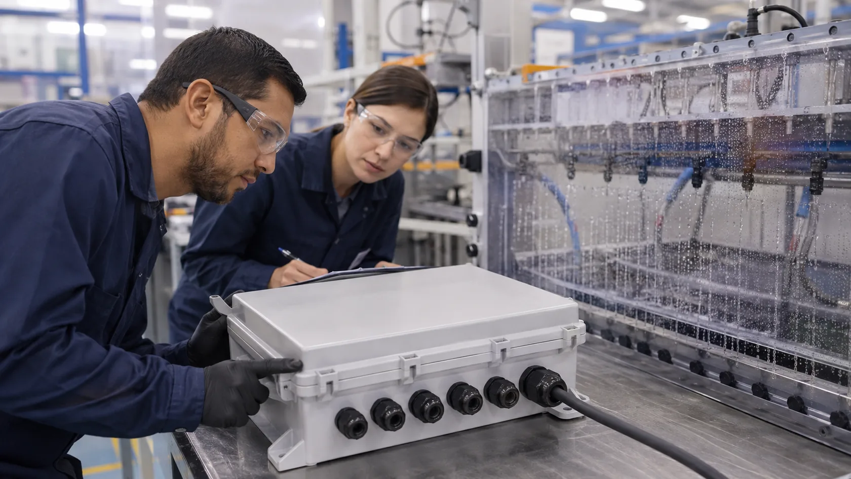
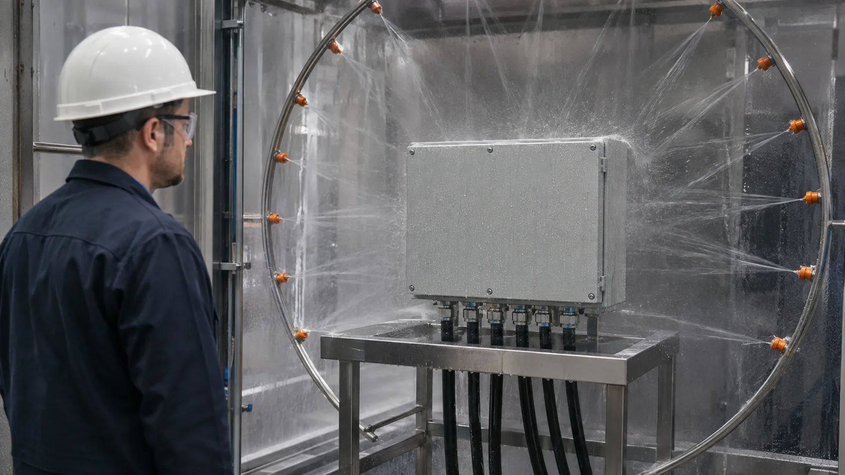
The specified ingress test should use the intended enclosure revision, gasket, finish, closure hardware, cable glands, plugs, connectors, and service position. If a customer will add components later, define the approved component set and installation method instead of silently extending the original result.
Keep the test record connected to production
Request or retain the standard edition, test method, sample configuration, drawing revision, orientation, preconditioning, inspection result, and any deviations. Then carry the critical features into production control: gasket part number, lot traceability where needed, groove inspection, coating limits on the sealing surface, fixture settings, closure process, and change review.
| Control stage | Purpose |
|---|---|
| Design validation | Demonstrate the defined assembly against the named water-exposure method |
| First article | Confirm tooling, finish, gasket, and assembly match the released design |
| Routine control | Check seating, closure, accessories, and visible damage before shipment |
| Change review | Reassess modified gasket, supplier, coating, cutout, or closure method |
A single pass report is valuable, but it is not a lifetime guarantee for every production variation. I prefer a modest, well-documented test plan plus stable assembly controls over an ambitious rating claim with no configuration record.
Conclusion
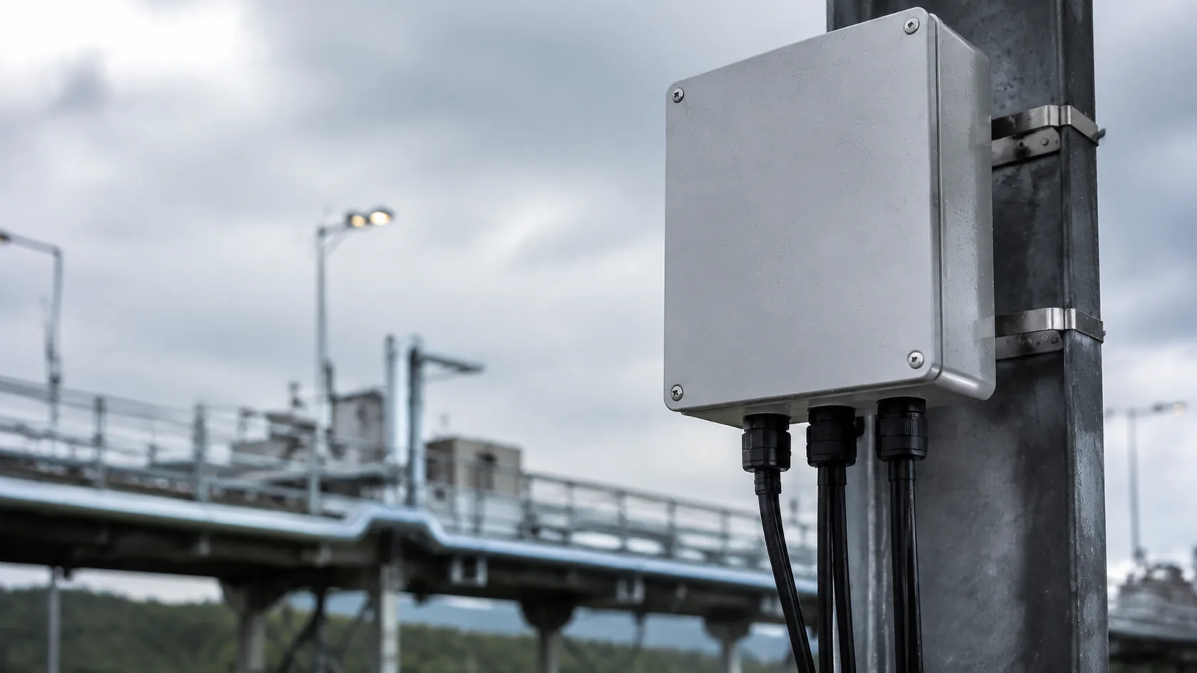
The right waterproof enclosure seal is usually a system choice: the gasket format, elastomer compound, groove or flange, cover stiffness, closure force, entries, orientation, and validation method all need to agree. Foam, molded gaskets, and O-rings can each work very well when used in the conditions they were designed for.
In my experience, the best time to resolve the trade-offs is while the drawing still allows a better groove, a stiffer lid, or a clearer cable-entry plan. Share the intended environment, enclosure drawing, entry layout, service cycle, and required standard, and we can review the sealing path before tooling or production begins.