Skip to content

A metal enclosure can sit on the table looking clean, expensive, and fully under control, and still fail EMC because of a line so small that most people would ignore it.
That line is often the seam.
I have seen teams spend serious time on PCB layout, cable routing, grounding points, and filter parts, only to get hit by a result that points back to the enclosure joint. That moment always changes the mood. The seam looked tight. The screws were there. The surface finish looked nice. Still, the shielding path was weak where it mattered most.
I think this is one of those problems that fools smart people because it hides behind appearance. A seam can look fine and still behave badly in electrical terms. That is why I do not judge a seam by how neat it looks after assembly. I judge it by whether current can pass across it in a stable way when the product is coated, fastened, moved, tested, shipped, and used.
Many engineers naturally stare at the PCB first. I understand that. The board feels like the center of the product. But EMC leakage often comes from the edges, the covers, the joints, and the small physical details that do not look dramatic in a CAD drawing. A small seam gap can quietly become the real problem.
The part that has changed my thinking over the years is simple: EMC performance depends on continuous conductive paths, not visual tightness. That sounds obvious when written in one sentence. In real work, it gets missed all the time.
This topic matters because seam problems do not only hurt test results. They hurt schedules, margins, and trust. A failed EMC test can delay delivery. It can force rework. It can create long email chains across time zones. It can make a buyer wonder whether the factory truly understands the product.
I care about that part too, because I work with buyers and engineers who need answers fast, not excuses.
Why do small seam gaps matter so much in EMC?

A lot of people hear small gap and think small problem. I do not blame them. That is how the eye works. We compare size to what we can see and touch. EMC does not care about that comfort. EMC cares about what the gap does to the electrical path.
The first mistake is treating seam size like a visual quality issue only. The second mistake is assuming that if the gap is hard to notice, it is too small to matter. That idea has caused more trouble than many people want to admit.
One thing I weigh early is whether the seam sits in a place where high-frequency energy is likely to punish even a tiny weakness, because a gap that feels trivial in machining can become very loud in EMC.
The relationship between wavelength and gap size
When I explain this to customers or younger engineers, I try to keep it simple. High-frequency energy is much less forgiving than low-frequency energy. As frequency goes up, wavelength gets shorter. As wavelength gets shorter, smaller physical openings begin to matter more.
So yes, a seam that looks tiny can still create trouble if the frequency is high enough.
That is why products with fast digital signals, switching power circuits, wireless functions, or noisy internal sources can become sensitive to seams very quickly. The enclosure is not only a box. It is part of the electrical system.
Here is a simple way I think about it:
| Factor | What happens | Why it matters |
|---|---|---|
| Lower frequency | Larger wavelength | Small gaps may have less effect |
| Higher frequency | Shorter wavelength | Small gaps become more dangerous |
| Longer seam length | More chance to radiate | Leakage can spread along the joint |
| Poor contact continuity | Higher impedance | Shield currents lose an easy path |
A seam does not need to be huge to matter. It only needs to be electrically inconvenient at the wrong frequency.
Slot antenna effect explained in simple terms
This is where people start to pay attention. A narrow gap can act like a slot antenna. That phrase sounds technical, but the basic idea is not hard: the opening can let energy escape and radiate.
I often explain it like this. If the enclosure is supposed to behave like a shielded shell, then the seam is the weak zipper. If the zipper does not close electrically, the energy finds that line and starts using it.
That is why a seam can radiate more efficiently than people expect. The gap may be narrow, but if it has enough length and poor enough continuity, it becomes useful to the noise trying to get out.
I have seen products where the machining looked precise and the finish looked premium, but the EMC failure still centered around the lid joint. On paper, that confused the team. In reality, the seam had become the slot.
Why “visually small” is not “electrically small”
This is the trap. People see a gap and think in millimeters. EMC often cares more about impedance, contact quality, oxide layers, coatings, pressure, and current path continuity.
A seam can look tightly closed and still perform badly because of:
- anodizing on the contact area
- powder coating on mating surfaces
- light pressure instead of firm pressure
- uneven screw torque
- warped parts
- oxide growth over time
I have handled enclosure samples that looked almost perfect from a cosmetic view, yet the seam was electrically unreliable. That difference matters a lot in real products.
Here is the contrast I keep in mind:
| Visual impression | Electrical reality |
|---|---|
| Seam looks narrow | Contact may still be weak |
| Surface looks premium | Coating may block conduction |
| Screws are present | Pressure may still be uneven |
| Lid sits flat | Current path may still be broken |
A neat seam is not the same thing as a conductive seam. That is one of the most expensive little truths in enclosure work.
That idea usually surprises people at first. Then they start looking at seams in a different way, which is exactly where the next problem begins: how leakage actually happens.
How do seam gaps actually cause EMI leakage?

I think seam leakage becomes much easier to understand once we stop treating the enclosure like a dead piece of metal. It is not dead. At high frequency, current moves on surfaces, fields react to discontinuities, and the enclosure becomes active in the EMC story.
That is why a seam is not only a mechanical joint. It is also part of the return path.
From my side, I get suspicious as soon as a seam forces current to make a clumsy detour, because high-frequency current does not like detours and usually turns that dislike into leakage.
Disrupted current return paths
Shielding works best when current can flow across the enclosure surface without interruption. If the seam is conductive and continuous, surface current moves along the shell more smoothly. If the seam has poor contact, the path gets disrupted.
Then the current has to find another route.
That detour creates trouble. It increases impedance. It disturbs current flow. It makes radiation more likely. A seam that should have been electrically quiet becomes active.
I like to describe it in plain language: the current wanted a straight road, but the seam gave it potholes and broken pavement.
This is why seam quality cannot be treated as decoration or only assembly detail. It directly affects how shield currents behave.
High-frequency currents and surface behavior
At high frequency, current tends to stay near the surface. That is why surface condition matters so much. People sometimes focus on bulk metal thickness and forget that the behavior near the surface is what often decides the result.
If the surface path is interrupted at the seam, the weakness shows up quickly.
That is where skin effect enters the conversation. I do not think every buyer needs a deep physics lecture on it. But they do need the practical point: high-frequency current lives where coatings, contact pressure, and seam continuity matter most.
A few practical observations explain a lot:
- Thick walls do not save a bad seam.
- Nice-looking finish does not guarantee a good electrical path.
- A narrow gap can be worse than expected when surface current hits it at the wrong frequency.
- Repeated contact points work better than one or two isolated pressure spots.
Resonance and amplification at seams
This part is the one that frustrates teams most. Sometimes a product looks mostly fine, then fails badly at a certain frequency band. That sudden jump feels strange until you remember that seams can resonate.
Some seam lengths interact with certain frequencies in a way that boosts leakage. So the problem is not always smooth and predictable. It can spike.
That is why EMC testing can feel unfair to people who are seeing the issue for the first time. The product may pass comfortably in one area and then fall apart in another. The seam did not randomly become worse. The frequency made the weakness easier to excite.
Here is a simple table I use when thinking through this:
| Seam behavior | Likely EMC effect |
|---|---|
| Broken conductive path | More leakage |
| Longer straight seam | Higher radiation risk |
| Weak pressure at intervals | Inconsistent shielding |
| Frequency aligns with seam behavior | Sharp failure peaks |
That unpredictability is exactly why I do not trust visual confidence alone. A seam can stay quiet for part of the scan and then suddenly become the loudest thing in the product.
Once people understand that, the next question gets more practical: why do real products make this worse than expected?
What makes seam gaps worse in real products?

This is where theory meets factory reality, and factory reality is usually less polite.
In CAD, seams often look precise. In production, parts have coatings, tolerances, warpage, handling marks, assembly variation, and time pressure. That is when a decent seam on screen turns into a risky seam on the bench.
The detail I never ignore is how many small imperfections can stack together into one bad EMC result, because seam problems rarely come from one dramatic mistake.
Surface coatings and anodizing
I work with aluminum enclosures often, so I have seen this issue again and again. Anodizing looks good. It improves corrosion resistance. It helps the product feel premium. It also creates an oxide layer that is electrically insulating.
That matters a lot at mating surfaces.
If two anodized faces meet, many people assume metal is touching metal. In real electrical terms, that is often not true. Oxide is touching oxide. The seam may look solid, but the conductive path is poor.
Powder coating is even more obvious. It can block contact almost completely unless the design intentionally removes it from the right areas.
Here is how I usually compare surface conditions:
| Surface condition | EMC contact quality | Common mistake |
|---|---|---|
| Bare conductive metal | Usually better | Assuming corrosion is the only concern |
| Anodized surface | Often poor unless masked | Thinking “it is still aluminum” |
| Powder-coated surface | Very poor at contact zones | Letting coated faces mate directly |
| Selectively masked contact area | Much better | Not controlling the masking well |
This is one of those places where product appearance and EMC needs can fight each other. That tension has to be managed, not ignored.
Poor mechanical tolerance control
A seam can fail without any dramatic visual gap simply because the parts are not truly aligned or flat enough.
I have seen lids that looked acceptable until we checked them more carefully. A slight warp. A slight bend. A tiny angle mismatch. None of it looked shocking. Together, they created inconsistent seam contact.
Tolerance stack-up makes this worse. One small variation in one part may be fine. Several small variations at once can create micro gaps across a long seam.
That is why I look beyond nominal drawing values. I want to know what happens when real parts from a real batch come together.
Some practical risk sources are:
- lid flatness drift
- flange bending
- hole location deviation
- cutout distortion after machining
- weak structural stiffness in larger panels
A seam can be “in tolerance” and still be poor for EMC. That sentence has annoyed many people, but it is true.
Fastener spacing and pressure distribution
I have seen many enclosures where the screw count was chosen mainly for assembly convenience or cost. That is understandable. Fewer screws mean simpler assembly and lower hardware cost. But wide fastener spacing can leave sections of the seam poorly pressed.
Then the seam becomes electrically uneven.
One part of the joint may have good contact. Another part may open slightly under stress or simply sit with lighter pressure. EMC does not average that out kindly.
This is how I think about fastener design:
| Fastener choice | Likely seam result |
|---|---|
| Wide spacing | Weak pressure between screws |
| Close spacing | Better contact consistency |
| Uneven torque | Patchy electrical bonding |
| Better joint geometry plus good spacing | More stable seam performance |
I do not only ask, “Are there enough screws?” I ask, “Where is the pressure weakest, and what happens there when the product gets shaken, heated, or reassembled?”
Wear, vibration, and long-term degradation
A seam that barely passes on day one may fail later in the field.
That is not always because the design was terrible. Sometimes the design had no margin. Vibration loosens contact. Repeated opening and closing wears surfaces. Oxidation increases resistance. Shipping stress changes pressure at the joint.
This is where short-term thinking causes long-term pain.
I have seen products behave acceptably during sample evaluation and then become less stable after handling, transport, or repeated maintenance. That is why I do not trust a seam that only works in fresh, ideal condition.
A seam needs to survive real life, not just a photo.
That reality leads to another uncomfortable question: why do so many designs still underestimate seam problems in the first place?
Why do many designs underestimate seam problems?

I think this happens because seam problems are quiet problems. They do not look heroic. They do not get the same attention as a processor, a power stage, or an antenna layout. But they can still wreck the project.
Design teams often underestimate seams because the joint sits in the border zone between mechanical design, electrical behavior, finishing, and assembly. When a topic belongs to everyone a little, it often gets owned by no one enough.
The part that usually gets missed is not the existence of the seam, but the false confidence around it.
Overconfidence in metal-to-metal contact
I understand why this idea is attractive. Two metal parts come together. The screws tighten them. Done. It sounds clean and practical.
But metal-to-metal contact is not a magic phrase. Real contact depends on surface condition, contact pressure, flatness, roughness, and how much true conductive area is actually touching.
I have seen projects where people said, “It is all metal, so shielding should be fine,” and I already knew we were too relaxed.
The truth is more annoying:
- metal may be coated
- contact may be only at a few peaks
- pressure may be weak between screws
- oxide may block continuity
- repeated assembly may change the contact behavior
A metal seam is not automatically a good seam.
Focus on structure instead of conductivity
Mechanical design often focuses first on strength, assembly ease, appearance, and cost. That is normal. Those are real needs. But when seam decisions are made mainly for structure, electrical continuity can become an afterthought.
Then the team ends up with:
- good rigidity
- nice fit
- easy assembly
- poor shielding continuity
I have seen lids designed with strong mechanical logic but weak EMC logic. The structure held up well. The seam did not conduct well. The enclosure looked convincing and still leaked.
Here is a comparison that comes up often in real work:
| Design priority | Good result | Hidden risk |
|---|---|---|
| Structural stiffness | Strong housing | Seam may still leak |
| Cosmetic finish | Premium appearance | Contact may be insulated |
| Low hardware count | Lower cost | Pressure may be uneven |
| Easy assembly | Faster production | EMC may be unstable |
None of these priorities are wrong. The problem starts when the team assumes they automatically solve EMC too.
Lack of early EMC consideration
This is the part that costs the most money.
Many projects leave real EMC evaluation until late. At that point, the enclosure design is already mature, tooling may be fixed, and the customer schedule may be tight. Then a seam issue appears, and the options are ugly.
You patch it.
You slow the project.
You add cost.
You redesign late.
You argue in meetings.
I always feel that seam issues become cruel when they are discovered late, because the fix may be simple in concept but painful in project timing.
A late seam fix often means:
- extra machining changes
- masking changes
- gasket addition
- extra screws
- assembly update
- retesting
- documentation changes
That is why I prefer to treat seam behavior as an early design topic, not a late test surprise.
Once that mindset changes, the next smart move is obvious: identify the risk early, before the chamber does it for you.

I like finding seam problems before the formal test lab does, because the lab is a very expensive place to learn basic truths.
The good news is that early warning signs often exist. The bad news is that people do not always look for them in the right way. A quick visual check is useful, but it is not enough. A seam can fool the eye very easily.
I do not trust a seam just because it looks straight and tight; I want some proof that the electrical path is real, not imagined.
Visual inspection vs electrical validation
Visual inspection has value. I do it all the time. I look for obvious warping, uneven gaps, poor fit, weak flange support, coating on contact zones, and screw layout problems.
But visual inspection is only step one.
A seam that looks uniform may still have poor electrical continuity. So I also want to validate it electrically when the risk is meaningful. That may mean checking resistance across the joint, looking at contact consistency, or using early EMC tools to see where energy escapes.
This basic comparison helps a lot:
| Check type | What it can tell me | What it cannot guarantee |
|---|---|---|
| Visual check | Gap shape, fit, coating presence | True EMC performance |
| Resistance check | Basic continuity quality | Full radiated behavior |
| Near-field probing | Leakage hotspots | Final compliance margin |
| Pre-compliance chamber test | Early EMC weakness | Exact final certification outcome |
People get into trouble when they stop at the first row.
Simple diagnostic methods
You do not always need a huge formal setup to learn something useful.
Some simple methods can reveal a lot:
- continuity check across the seam
- contact resistance comparison at different seam points
- near-field probing along the joint
- temporary copper tape test to see if sealing the seam changes the result
- extra clamp or temporary screw test to see whether pressure improves performance
I like temporary tests because they answer a practical question fast: Is the seam really the problem?
If adding temporary conductive help makes the emission drop, that is a strong clue. Not the whole answer, but a strong clue.
EMC pre-compliance testing
I think pre-compliance testing is one of the best investments for products that have real EMC risk. It is cheaper than late panic. It is faster than repeated guesswork. It is also emotionally easier on the team.
There is something very different about discovering a seam weakness during a flexible early stage instead of discovering it when delivery promises are already hanging over everyone’s head.
This is how I compare timing:
| Timing of seam discovery | Typical project impact |
|---|---|
| Early prototype stage | Manageable correction |
| Pilot run stage | More cost, more pressure |
| Formal test failure stage | Delay, blame, rushed patches |
| After shipment | Worst-case trust damage |
I would rather learn early that the seam is weak than learn late that the schedule is weak.
Once the risk is visible, the conversation becomes much more useful: what design choices actually reduce the problem?
What design strategies reduce seam gap problems?
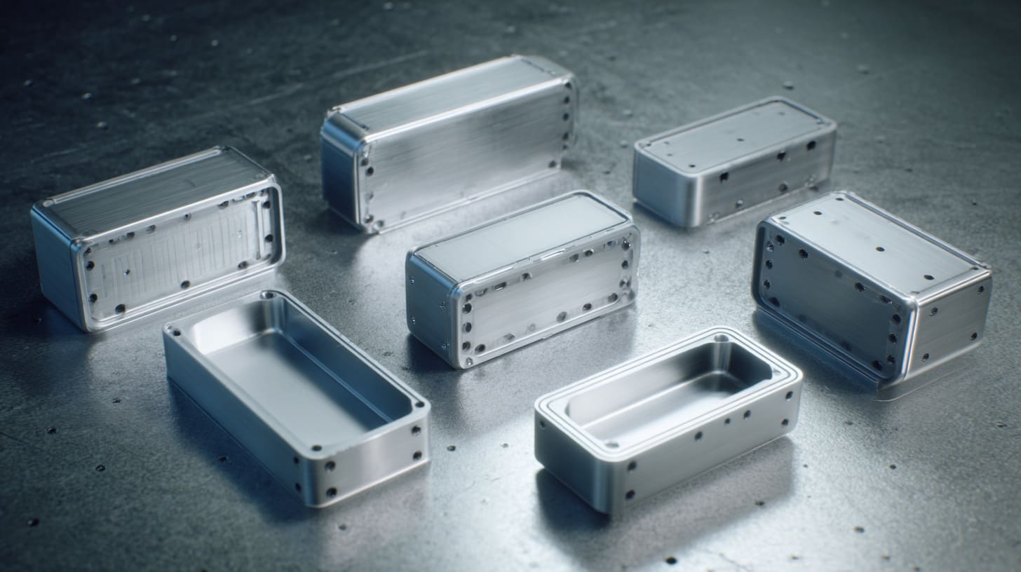
This is where enclosure design gets interesting for me, because good EMC design is rarely about one magic fix. It is usually about several sensible decisions working together.
I do not look for a clever trick first. I look for whether the seam can keep a stable conductive path in normal production, not only in one lucky sample.
Increase contact reliability
The first goal is simple: make the seam contact more reliable.
That can come from conductive gaskets, conductive coatings at contact points, better joint geometry, or more intentional metal contact zones. The exact choice depends on the product, the frequency range, the environment, and the cost target.
Conductive gaskets can help a lot, especially when the design needs repeated opening and closing or when tolerance variation is hard to avoid. But I do not treat gaskets as magic either. A bad joint plus a gasket can still become a bad EMC story if the compression is wrong.
Some common approaches:
| Method | Benefit | Caution |
|---|---|---|
| Conductive gasket | Fills irregularities, improves contact | Needs correct compression |
| Conductive fingerstock | Good for removable covers | Adds cost and space needs |
| Conductive coating | Helps targeted contact areas | Process control matters |
| Bare masked seam zone | Direct metal contact | Corrosion and finish balance matter |
Optimize fastener design
Fasteners do more than hold the product together. They shape seam pressure.
If screw spacing is too large, the seam between screws may relax. If torque is inconsistent, pressure becomes uneven. If the joint geometry is weak, the screws may create islands of contact instead of a continuous path.
I often tell people that the seam behaves between screws, not only at screws.
That is why I look carefully at:
- spacing between fasteners
- torque repeatability
- stiffness of the mating flanges
- position of screws near corners and cutouts
- how often the cover will be removed in service
A cheap hardware decision can become an expensive EMC correction later.
Design for continuous contact paths
I like seam designs that make leakage work harder.
Straight-line gaps are often more vulnerable. Overlapping lips, stepped joints, tongue-and-groove shapes, or labyrinth-style paths can improve the electrical and radiated behavior. These features do not erase all risk, but they make the seam less willing to act like a clean leakage slot.
That matters a lot when the product has aggressive EMC conditions.
Here is a quick comparison:
| Seam style | EMC tendency |
|---|---|
| Simple straight seam | Higher leakage risk |
| Overlap seam | Better path control |
| Labyrinth seam | Harder for fields to leak directly |
| Poorly supported seam with long span | Often unstable |
I do not choose seam geometry only for appearance or ease of machining. I ask what kind of path I am creating for both current and leakage.
Control surface treatment
This topic gets missed all the time, especially when appearance is important.
If the contact area is anodized, powder-coated, or otherwise insulated, the seam may fail even if the geometry is decent. So the surface treatment plan has to match the EMC plan.
That may mean:
- masking contact areas before anodizing
- using selective conductive finish
- protecting bare contact zones from corrosion in a controlled way
- clearly defining contact surfaces in drawings and production notes
The word in the outline mixed languages, but the real meaning is clear: contact areas must stay electrically useful.
I think this is one of the most practical trade-offs in enclosure work. Customers want a premium finish. EMC wants conductivity. Good design finds a smart balance instead of pretending there is no conflict.
Good design is only half the story, though. A smart seam on the drawing can still fail if the factory process is loose.
What manufacturing practices improve EMC performance?
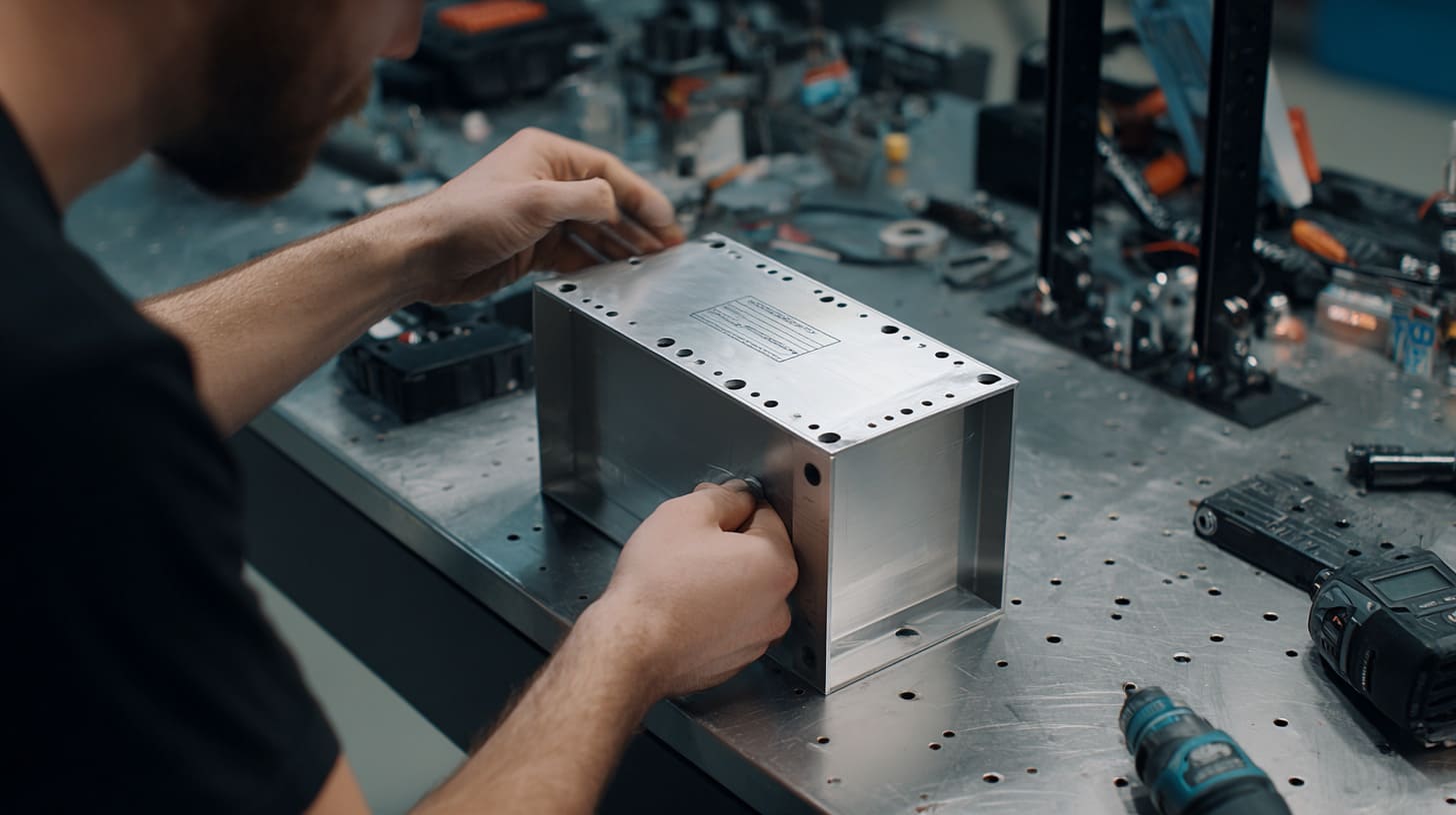
I have learned this lesson the hard way: a sound EMC design can still become a weak product if manufacturing does not protect the seam conditions that the design depends on.
That is why I do not separate design from process in my mind. If the seam needs flatness, clean contact zones, controlled torque, and alignment, then production has to deliver those things again and again.
My real concern is not whether one sample works, but whether the fiftieth and five-hundredth pieces still keep the same seam behavior.
Tight tolerance control
Precision matters here, but not in a vague marketing sense. It matters in specific ways.
If the flange is not flat enough, the seam will not contact evenly.
If the lid bends, pressure will drift.
If the holes are off, the joint may pull into a stressed shape.
That is why I like tolerance reviews that focus on seam function, not only general dimensional pass/fail status.
Important process checks often include:
- flatness of mating surfaces
- parallelism of lid and base contact zones
- hole position accuracy
- flange stiffness after machining or forming
- consistency across batches
I have seen “acceptable” variation become unacceptable once EMC entered the room.
Assembly process consistency
Assembly is where many good intentions go to die.
A proper seam can become unreliable if the tightening order is inconsistent, the torque is uncontrolled, or the operator presses the joint unevenly during assembly. This is not glamorous work, but it matters.
I prefer controlled fastening sequences because they reduce randomness. One enclosure should not pass because one worker happened to tighten the screws in a more EMC-friendly order than another worker.
Here is a practical table:
| Assembly variable | Risk if uncontrolled |
|---|---|
| Torque level | Weak or uneven contact |
| Tightening sequence | Warped or twisted seam |
| Surface cleanliness | Higher contact resistance |
| Rework handling | Scratched finish or damaged contact zones |
A seam needs process discipline more than many people expect.
Quality inspection for electrical contact
QC often focuses on dimensions, scratches, color, and fit. Those matter. But for EMC-sensitive products, they are not enough.
I like QC steps that include seam-related electrical checks when the application justifies it. Not every project needs a heavy inspection burden. But if EMC performance matters, then checking contact resistance or defined seam continuity points can save a lot of pain later.
A seam that passes visual inspection and fails electrically is still a failed seam.
That sentence may sound harsh. It is also very real.
So for EMC-related products, I think QC should ask a few extra questions:
- Are the contact zones properly exposed?
- Is coating creeping into masked areas?
- Is the fastening result consistent?
- Are electrical contact values within expectation?
- Do sample units show similar seam behavior?
This is where manufacturing earns trust. Not by saying the parts look fine, but by proving the seams work the way the design intended.
Still, even with good design and solid manufacturing, there are cases where the seam keeps causing trouble. That is when a harder decision shows up.
When should you redesign instead of patching the seam?
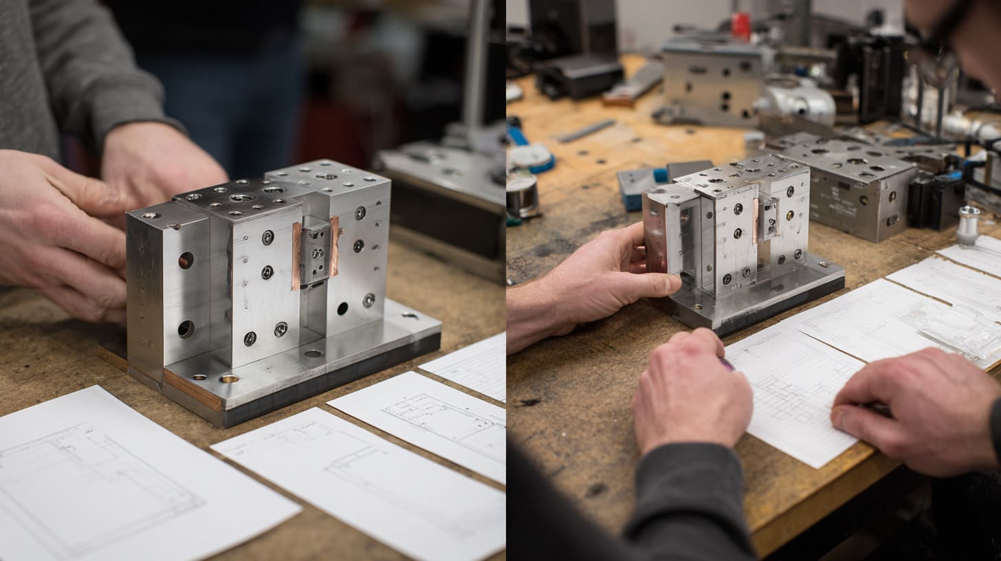
I think every engineer and buyer eventually faces this uncomfortable question: do we keep patching, or do we step back and redesign?
Temporary fixes can be useful. I am not against them. Extra screws, copper tape, conductive gasket additions, and contact surface changes can all help. But sometimes those fixes are signals, not solutions.
I start leaning toward redesign when the seam only behaves after too many special tricks, because a product that needs constant rescue is usually telling the truth about its design.
Signs of fundamental design issues
Some warning signs are easy to miss because each one feels manageable on its own.
But when I see several together, I stop thinking in patch mode.
Typical signs include:
- repeated EMC failures at the same seam area
- big improvement only after temporary tape or clamp fixes
- dependence on very tight assembly conditions to pass
- too many extra screws added after the first design
- finish requirements fighting the contact requirement every time
- unstable performance across samples
A patch is useful when it supports a basically healthy concept. A patch is dangerous when it is hiding a weak concept.
Cost comparison: redesign vs workaround
This is where project emotion and project economics collide.
A redesign costs money. Everyone sees that. What people often see less clearly is that repeated workaround cost also adds up fast.
You pay in:
- extra assembly time
- more hardware
- more inspection steps
- retesting
- documentation updates
- field risk
- buyer frustration
Here is how I usually frame it:
| Option | Short-term feeling | Long-term effect |
|---|---|---|
| Quick workaround | Feels faster | Can grow hidden cost |
| Partial seam patch | Useful in some cases | May reduce margin and stability |
| Proper redesign | Feels painful now | Often cleaner and safer later |
I have been in projects where the team tried to save the design for too long because redesign felt emotionally expensive. Then the workaround path became even more expensive.
Balancing performance, cost, and manufacturability
Not every enclosure needs extreme shielding. I think this point matters because people can overreact too. The right answer depends on the product use case.
A simple industrial controller, a consumer device, and a dense high-speed electronic product may need different seam strategies. Good judgment means matching the seam solution to the real EMC demand, the production volume, the service model, and the finish requirement.
I do not chase the most aggressive seam design by default. I chase the level of control that fits the real job without creating unnecessary cost or factory pain.
That balance usually comes down to three questions:
- How severe is the EMC risk?
- How repeatable is the production method?
- How expensive will failure be later?
If the answers point toward high risk, low repeatability, and high failure cost, redesign becomes easier to justify.
And that brings me to the part I care about most: what all of this says about how I make enclosure decisions in real work.
Conclusion

I take small seam gaps seriously because I have seen how often they pretend to be minor and then become the reason a product fails when the pressure is already high. That is why I do not trust appearance alone. I care about conductivity, pressure, continuity, finish control, and whether the seam will still behave after normal production and normal handling.
I think that way because enclosure work has taught me the same lesson more than once: reliable shielding comes from controlled contact, not assumption. A seam is never just a line between two metal parts. It is part of the current path. It is part of the EMC result. It is part of the delivery risk too.
I also believe this because I work close to the practical side of projects. Buyers do not only want theory. Engineers do not only want elegant explanations. They want answers that survive tooling, assembly, shipping, and deadlines. A seam that barely works in one sample is not good enough for me. I would rather face an uncomfortable design truth early than explain a late failure after the schedule slips.
That is why I keep coming back to the same idea: I do not judge a seam by how neat it looks. I judge it by whether it keeps a stable conductive path when the real world starts pushing on it.
If you are working on an enclosure project and you are not fully sure about your seam design, this is a good time to check it before EMC testing checks it for you. If you want, you can send me your enclosure drawing, seam structure, or surface finish plan, and I can help you review the risk points from a practical manufacturing view.