Skip to content

A screw can make an enclosure feel finished very fast.
I have seen that feeling many times in real projects. A lid is aligned. The corners sit flat. The fasteners are tightened. The shell feels solid in the hand. At that moment, many people relax. They look at the assembly and think, good, the bonding is handled too.
That is where trouble starts.
I once worked on an aluminum enclosure for an industrial control device. The drawing looked clean. The machining was neat. The fit between the top and bottom covers was good. Nothing felt risky at first glance. Then the sample moved into testing. The problem did not come from the PCB. The problem did not come from the dimensions. The problem came from a quiet assumption: the screws were expected to do more than they really could.
The enclosure passed the “looks fine” test. It did not pass the “works well under real conditions” test.
That lesson stayed with me. A screw is very good at clamping parts together. A screw is not always good at giving me a stable electrical bond. Those are two different jobs. People mix them together all the time because the hardware is the same. The result is confusion, late fixes, and sometimes ugly EMC results.
What makes this issue more frustrating is that screw-based bonding can appear to work in the early stage. The meter may show continuity one moment. The assembly may feel tight. The unit may even run well on the bench. Then vibration, coating, oxidation, humidity, or repeated opening changes the contact quality, and the weakness shows up when nobody wants surprises anymore.
I do not judge bonding by how tight the screw feels in my fingers. I judge it by whether the electrical path stays stable after finish, assembly, shipping, and use.
In this article, I will explain when I do not trust screws as the main bonding method in aluminum enclosures, why that choice matters, and what I prefer instead when the project carries real EMC, safety, or long-term reliability pressure.
That sounds like a small detail. It is not. It is one of those details that can quietly decide whether a design behaves like a product or just a nice sample.
What Does “Bonding” Really Mean in Aluminum Enclosures?

Before I decide whether screws are enough, I need to be very clear about one thing: what kind of bonding am I even talking about?
A lot of confusion begins here. Some people use “bonding” when they mean simple assembly contact. Some people mean grounding. Some people mean shielding. Some people mean safety. These are close ideas, but they are not the same.
The first thing I sort out is whether the customer needs the enclosure to merely stay assembled, or whether the enclosure must also carry a dependable electrical path under real working conditions.
Difference Between Mechanical Fastening and Electrical Bonding
Mechanical fastening is simple. The goal is to hold parts together. A screw does this well. It pulls two parts into position. It keeps the lid from moving. It helps the enclosure survive handling, packing, and use.
Electrical bonding is different. The goal is not only contact. The goal is stable, low-resistance continuity between conductive parts. That continuity may be needed for safety grounding, shielding, signal reference, or all three.
I often explain it like this:
| Function | Main Purpose | Typical Question |
|---|---|---|
| Mechanical fastening | Keep parts physically together | Will the enclosure stay tight? |
| Electrical bonding | Keep conductive parts electrically connected | Will the enclosure keep a stable electrical path? |
That difference sounds basic. Still, many project mistakes begin right there. A part can be tightly fastened and still be poorly bonded.
Types of Bonding in Enclosures
When I review an aluminum enclosure, I usually think about bonding in three common ways.
Protective bonding
This is the safety side. If a fault happens, the enclosure should not become a hidden hazard. The conductive parts need a dependable path.
Functional bonding
This is where EMC and signal behavior start to matter. The bonding path helps control noise, leakage, and reference stability.
Equipotential bonding between panels
This matters when multiple metal parts make up one enclosure. If the top cover, base, side panels, and internal subparts do not stay at the same electrical potential, shielding performance can drop.
Here is how I keep those ideas separate:
| Bonding Type | Why It Matters | What Usually Goes Wrong |
|---|---|---|
| Protective bonding | User safety | Assumed path is weak or unstable |
| Functional bonding | EMC and signal control | Contact exists but impedance is poor |
| Equipotential bonding | Whole enclosure acts as one body | Panel seams become weak points |
Why Aluminum Makes Bonding More Complicated
This is the part many buyers and even some engineers underestimate.
Aluminum is useful. I work with it all the time. It is light, workable, and good-looking. But aluminum also creates bonding headaches because the surface is not as simple as people imagine.
Aluminum naturally forms an oxide layer. That layer protects the metal, which is great for corrosion resistance. But it also makes electrical contact less straightforward. Then many projects add anodizing, powder coating, or painting. Those finishes help appearance and durability. At the same time, they make surface conductivity worse.
That is why a screw touching aluminum does not automatically mean I have a dependable bond.
I have seen good-looking anodized enclosures where the whole bonding plan was basically “the screws will bite through.” Sometimes that works a little. Sometimes it works at first. Sometimes it fails in the exact way that wastes the most time: not fully, not clearly, just enough to create unstable behavior.
A Practical Way I Think About Bonding
When I review a design, I do not ask only, “Are these two parts touching?”
I ask:
- Are they touching through bare conductive surfaces?
- Is the contact area big enough?
- Will the contact stay good after finish and assembly?
- Will that path remain stable after vibration, humidity, and maintenance?
- Is the screw doing an electrical job it was never chosen for?
That is the real question.
And once I frame it that way, the limits of screw-only bonding become much easier to see.
That brings me to the next problem, which is not technical at first. It is psychological. Screws are popular because they make people feel like bonding is already solved.
Why Screws Are Commonly Used for Bonding (and Why That’s Misleading)

I understand why screws get used for bonding so often.
They are already in the design. They are cheap. They are visible. They create pressure between parts. On a drawing, they make the enclosure look complete. In the factory, they are easy to assemble. So the idea sounds reasonable: if the parts are clamped together with metal hardware, surely the electrical path is fine too.
That idea is convenient. It is also where a lot of weak designs begin.
What usually makes me nervous is not the screw itself, but the moment someone treats that screw as a free electrical solution just because it is already there.
Convenience in Design and Assembly
From a design view, screws are attractive.
A mechanical engineer already needs them for structure. A purchaser already expects them. A factory already stocks them. Nobody needs to add a special strap, gasket, or extra step if the screws can “do both jobs.”
That saves time on paper.
Here is why teams like that approach:
| Reason Screws Get Chosen | Why It Feels Good Early | What It Hides |
|---|---|---|
| Already part of assembly | No extra hardware needed | Bonding requirement may be vague |
| Easy to model in CAD | Looks neat and complete | Electrical path is assumed, not proven |
| Low part cost | Helps quotation look better | Field risk is pushed later |
| Fast assembly | Good for production speed | Contact quality may vary unit to unit |
I do not blame people for liking simple solutions. I do the same thing when a simple solution is truly enough. The problem is that enclosure bonding often looks simple while behaving in a very messy way.
Assumption of Metal-to-Metal Contact
This is one of the most common wrong assumptions I see.
Someone says, “The screw goes through both panels, so there is metal-to-metal contact.”
Maybe. Maybe not.
If the enclosure is anodized, painted, or powder coated, the screw may only create tiny point contact. That contact may be inconsistent from one fastener to the next. It may depend on torque, coating thickness, burr condition, washer choice, or how the operator assembled it.
I have seen designs where one sample looked fine, but the next three units showed very different continuity values. That kind of variation tells me the design is depending on chance.
A tiny scratch through coating is not the same thing as a designed bonding interface.
Cost and Simplicity Bias
I also see a strong cost bias here.
Extra bonding parts look like “added cost.” Conductive gaskets cost money. Ground straps cost money. Masking coating at contact points costs money. Conductive finish control costs money. Extra test steps cost money.
So some teams try to avoid all that and let screws carry the whole burden.
I get the logic. I really do. Many customers are under price pressure. Many projects are racing toward sample approval. People want fewer parts, fewer drawings, and fewer discussions.
But this is where the cheap choice can become the expensive one.
I have watched teams save a few dollars in hardware and then lose much more in:
- rework
- EMC troubleshooting
- repeat assembly
- extra shipping
- delayed approvals
- customer confidence
That is why I do not judge screw-only bonding by piece price. I judge it by total project risk.
Why This Thinking Is Misleading
The misleading part is simple: screws create a strong visual signal.
A bonded strap looks intentional. A conductive gasket looks intentional. A masked contact zone on the drawing looks intentional. A screw also looks intentional, but it can trick people into believing the electrical design is finished when only the mechanical design is finished.
That difference matters a lot.
I have learned to be suspicious of anything that “probably should work” when the project includes coatings, EMC targets, vibration, or outdoor use. Those are exactly the cases where “probably” becomes expensive.
And once I start asking how the bond behaves under stress, the next issue becomes impossible to ignore: there are many real situations where screws simply do not hold up as a reliable bonding method.
When Screws FAIL to Provide Reliable Bonding

This is where the conversation stops being theoretical for me.
I do not reject screw-based bonding because of a textbook definition. I reject it when the real conditions make the contact unstable, weak, or too hard to trust. I have seen enough enclosure problems to know that failure rarely announces itself in a dramatic way. It creeps in through small details.
The fastest way I evaluate risk is by asking what will attack that screw contact first: finish, motion, frequency, environment, or time.
When Surfaces Are Anodized or Coated
This is one of the biggest reasons I refuse to rely on screws alone.
Anodizing, powder coating, and paint all help the enclosure in one way or another. They improve corrosion resistance. They improve looks. They help the product feel more finished. But they also get in the way of electrical contact.
A screw may scrape through some of that surface layer. Still, I do not like building a bonding plan around a scrape.
Why not? Because the actual conductive area can be tiny and inconsistent.
Here is how I look at it:
| Surface Condition | Mechanical Assembly | Electrical Bonding Risk |
|---|---|---|
| Bare aluminum | Usually easy | Lower risk, but oxide still matters |
| Anodized aluminum | Usually easy | High risk if no prepared contact zone |
| Powder-coated aluminum | Usually easy | Very high risk at seams |
| Painted surfaces | Usually easy | Contact quality is unpredictable |
When I see a coated enclosure and hear, “the screws will take care of bonding,” I slow down immediately. That sentence sounds simple, but it hides too much uncertainty.
Under Vibration or Mechanical Stress
A screw that bonds “well enough” on the workbench may not stay that way in transit or use.
Vibration changes things. So do repeated impacts. So does thermal cycling. Even small movement can reduce contact pressure or create micro-motion at the interface. Once that happens, resistance can rise. The path may become unstable.
This is where many sample-stage assumptions fail.
I have seen devices that behaved normally in the lab but became noisy after transport. Nothing looked broken. The enclosure still felt tight. The fault was not obvious. But the bonding path had changed just enough to create trouble.
That is why I never judge bonding only from a freshly assembled sample sitting still on a clean table.
In High EMC Requirement Applications
This is a dangerous area for wishful thinking.
If the enclosure is part of the shielding strategy, seam bonding matters. Not just physical closure. Not just “contact somewhere.” I need dependable electrical continuity across the right surfaces.
In high EMC projects, weak seam bonding can lead to:
- leakage through gaps
- poor shielding at panel joints
- unstable return paths
- emissions problems
- susceptibility problems
I have seen teams spend days discussing cables, ferrites, and PCB layout while the enclosure seam itself was quietly acting like the real weak point.
That is why I do not let a nice mechanical fit distract me from a poor electrical seam.
When Contact Area Is Too Small
Point contact is one of those small details that causes very large misunderstandings.
A screw head may clamp hard. But the actual conductive path may still be narrow, uneven, and too localized. That can be a poor choice where low-impedance bonding matters.
I often compare it like this:
| Contact Style | What It Looks Like | What I Think About It |
|---|---|---|
| Point contact | Simple and cheap | Easy to overestimate |
| Line contact | Better than point contact | Still depends on surface condition |
| Broad surface contact | More deliberate | Usually much more dependable |
A lot of engineers focus on whether there is some contact. I focus more on whether there is enough stable contact in the right place.
Those are not the same question.
In Corrosive or Humid Environments
Humidity is patient. Corrosion is patient too. They do not need to destroy the joint overnight. They only need to slowly change it.
Outdoor enclosures, marine-adjacent projects, wet industrial settings, and dusty sites with temperature cycling all create extra risk. The bonding path that seemed acceptable in the first month can drift over time.
This matters even more in aluminum because surface condition changes can quietly affect contact quality.
I do not like screw-only bonding in harsh environments because the design gives me too little control over long-term stability. I would rather define the path clearly than hope the fastener keeps doing two jobs well for years.
A Hard Truth I Have Learned
The hardest part about screw-based bonding failure is that it does not always fail in an obvious way.
The enclosure stays assembled. The screws stay present. The product looks professional. The issue hides inside a detail that most people cannot see after assembly.
That is exactly why I treat this topic seriously. Weak bonding is often a hidden failure, and hidden failures create the worst kind of project delay.
And once that hidden weakness exists, the next stage is even more painful, because the risks do not stay technical. They spread into testing, service, safety, and trust.
Hidden Risks of Relying Only on Screws

Some design problems are kind enough to show themselves early.
This one often is not.
That is why screw-only bonding can be so frustrating. A product may look stable. Assembly may feel normal. Continuity may even appear acceptable during a quick check. Then the weakness shows up later, in a place that is harder to diagnose and more expensive to fix.
The risk I worry about most is not total failure. It is partial failure that wastes time because nobody sees it clearly at first.
Intermittent Electrical Contact
This is one of the ugliest kinds of enclosure problems.
A unit works, then acts strangely. A test passes once, then fails later. A reading changes after reassembly. A customer says the issue is “not always there.” Those words usually mean trouble.
Intermittent contact is hard because it creates confusion. Teams start blaming boards, cables, software, or assembly quality. Sometimes the real problem is just an inconsistent bonding path at the enclosure seam.
I have seen this happen more than once. The enclosure looked fine. The screws were tight. Nobody wanted to suspect the screw joint because it looked too ordinary to be the source. But ordinary details cause many real failures.
EMC Test Failures
This is where weak bonding often becomes expensive very fast.
A project reaches EMC testing. The team expects a mostly smooth process. Then emissions or immunity results come back worse than expected. Now the search begins.
The painful part is that screw-only bonding can create a problem that feels bigger than it is. The team may begin redesigning board details, filtering, cable routing, or housing geometry when the seam bonding itself is unstable.
Here is a simple view of what I watch:
| Risk Area | What Weak Screw Bonding Can Cause |
|---|---|
| Enclosure seam | Leakage at panel joints |
| Ground reference | Inconsistent electrical behavior |
| Shielding path | Reduced effectiveness |
| Test repeatability | Different results after reassembly |
This is why I do not like “good enough” bonding language in EMC-sensitive products. EMC does not care whether the assembly looked neat. It cares whether the current path behaves the way the design expects.
Safety Risks
Not every enclosure project is safety-critical in the same way. Still, some are. And when they are, I become much less tolerant of vague bonding methods.
If a conductive enclosure depends on a stable grounding path for protection, I want that path designed on purpose. I do not want it to exist as a side effect of a screw choice.
A weak protective bond is not just an engineering mistake. It can become a user risk.
I have a simple rule in my own work: once the bonding function touches safety, I stop treating screw-only contact as a clever shortcut.
Maintenance and Lifecycle Issues
This point gets ignored too often.
Many enclosures are not sealed forever. People open them for repair, upgrade, inspection, or field service. Every time that happens, the contact condition can change.
A screw that bit through coating the first time may not behave the same way after repeated opening and closing. A washer may shift. A contact edge may wear. A technician may reassemble with different torque. Surface contamination may build up.
That means the bonding quality can drift during the product’s life, even if the original sample looked acceptable.
This is where things often go wrong in field reality: the first assembly gets all the attention, but the tenth assembly decides whether the design was actually robust.
Why These Risks Get Missed
Most of these risks hide because they do not announce themselves as “bonding problems.”
They show up as:
- unstable test results
- random noise behavior
- hard-to-repeat faults
- service complaints
- inconsistent unit performance
- unexplained enclosure sensitivity
That is why I try to catch bonding weakness on the drawing, not after the product starts teaching the lesson the hard way.
And once I see those risks clearly, the next decision becomes easier: there are situations where I should not even debate it. I should simply avoid screws as the only bonding method.
When You SHOULD Avoid Using Screws as the Only Bonding Method

I do not think screws are bad. I use them all the time.
What I reject is the habit of asking them to do every job at once.
There are projects where screw-only bonding might be tolerated if the conditions are mild and the design is simple. Then there are projects where that choice feels careless. In those cases, I would rather be a little more deliberate at the start than a lot more frustrated later.
If the project has high consequences for noise, safety, service, or environment, I stop debating convenience and start designing a dedicated bonding path.
High-Frequency or Sensitive Electronics
This is one of the clearest no-go zones for me.
RF gear, communication devices, control units with sensitive signals, and electronics that depend on good shielding do not reward casual seam bonding. Small impedance problems can matter. Small gaps can matter. Small variations in contact quality can matter.
That is why I do not like relying on scattered screw points as the main bonding strategy when the enclosure itself is part of the EMC solution.
The more sensitive the electronics are, the less I trust improvised contact paths.
Critical Grounding Applications
Some enclosures do not just “benefit” from bonding. They depend on it.
This includes many power-related devices, industrial control products, and systems where fault handling, protective grounding, or compliance requirements carry real weight.
In those projects, I do not want to explain later that the bonding path was mostly created by whatever the screw happened to bite through during assembly.
That is too vague for a critical function.
A simple way I think about it is this:
| Application Type | Can I Relax More? | Can I Trust Screw-Only Bonding? |
|---|---|---|
| Basic low-risk enclosure | Sometimes | Maybe, but still case by case |
| EMC-sensitive device | No | Rarely |
| Safety-critical conductive enclosure | No | I prefer not to |
| Industrial harsh-use product | No | Usually not |
Modular or Frequently Opened Enclosures
This is another category where I become cautious very fast.
Some enclosures are designed to be opened often. Others are opened because reality demands it. Service teams replace parts. Engineers inspect boards. Installers adjust wiring. Customers upgrade modules.
In these cases, the bonding system must survive repeated handling.
I do not like screw-only bonding here because the contact condition depends too much on repeated mechanical behavior. That is not the same as deliberate electrical design.
Outdoor or Harsh Environments
Outdoor air, salt exposure, moisture, dirt, and thermal cycling all make weak bonding choices worse.
A screw-only approach may still look attractive in quotation stage because it keeps the BOM simple. But in a harsh environment, simple on paper can become fragile in service.
I usually become very conservative when I see:
- outdoor mounting
- coastal exposure
- industrial washdown
- strong temperature swings
- dusty environments with moisture
- transport-heavy products
Those conditions do not create forgiving joints. They expose weak ones.
A Practical Rule I Use
I ask myself one plain question:
If this bonding path changes slightly after assembly, shipping, weather, or maintenance, will the product still behave the way I need?
If the answer is no, I do not let screws carry the whole job.
That is the point where better solutions start to make sense. And no, better does not always mean expensive or complicated. It often just means intentional.
Better Alternatives to Screws for Reliable Bonding

This is the part many people expect to be costly or hard.
Sometimes it is not.
A better bonding method does not always mean a dramatic redesign. Many times, it means choosing one or two deliberate features so the electrical path is stable instead of accidental.
When I compare options, I do not chase the most elegant method in theory. I look for the method that will stay dependable after finish, assembly, and real use.
Conductive Gaskets and EMI Shielding Materials
This is one of the strongest options when seam continuity matters.
A conductive gasket can create broad, repeatable contact along an enclosure seam. That is very different from hoping a few screw points will do enough on their own. In EMC-sensitive products, that wider contact can make a big difference.
I like this option when:
- the seam is long
- shielding matters
- panel-to-panel continuity needs to be stable
- repeated opening is expected
- the enclosure must balance sealing and conductivity
Here is a simple comparison:
| Method | Bonding Quality | Repeatability | Best Use Case |
|---|---|---|---|
| Screws only | Variable | Medium to low | Simple low-risk cases |
| Conductive gasket | High | High | EMC seams and repeat access |
| Ground strap | High | High | Dedicated grounding path |
| Prepared contact zone + hardware | Good | Good | Cost-balanced practical design |
Dedicated Grounding Straps or Wires
I like dedicated straps because they remove ambiguity.
Instead of hoping a lid screw provides a reliable path, a strap gives me a defined electrical connection. That matters when the project needs clear grounding logic.
This option is especially useful for:
- doors
- removable covers
- hinged panels
- internal subassemblies
- serviceable modules
A strap may not look as “clean” as pretending the screws do everything. Still, I would rather see an honest design than a pretty assumption.
Surface Preparation Techniques
Sometimes the best improvement is not adding a new component. It is defining the contact area correctly.
That can mean:
- removing anodizing at a bonding point
- masking coating before finishing
- using conductive plating where needed
- specifying bare-metal contact zones on the drawing
I respect this approach because it turns bonding from an accident into a requirement.
One small masked zone can do more good than five hopeful assumptions.
Use of Star Washers or Serrated Hardware
This is a helpful tool, but I treat it as support, not magic.
Star washers and serrated hardware can improve penetration through surface layers and help create better contact. That is useful. Still, I do not like pretending they solve every problem by themselves.
I use them when they fit the design. I just do not worship them.
Why? Because they still depend on local contact, assembly control, and long-term stability. They can improve a joint. They do not automatically transform a weak bonding concept into a strong one.
Welding or Riveting for Permanent Bonding
For some designs, permanence is the whole point.
If the assembly is not meant to be reopened and the project needs strong, low-resistance continuity, permanent joining methods can make sense. They reduce movement and remove some of the uncertainty that screw-only joints carry.
This choice is not right for every enclosure. It can reduce flexibility in service and manufacturing. Still, for the right product, it is a serious option.
How I Choose Among These Options
I do not choose by habit. I choose by the job.
I normally weigh five things first:
| Decision Factor | What I Ask |
|---|---|
| EMC need | Does the seam itself matter electrically? |
| Service need | Will people open this enclosure later? |
| Surface finish | Are coatings blocking conductivity? |
| Environment | Will moisture, vibration, or corrosion attack the joint? |
| Cost risk | Is a cheaper joint likely to become a costly failure? |
The best bonding choice is not always the fanciest one. It is the one that matches the real risk of the project.
And that choice works much better when it appears early in the design, not after testing starts complaining.
How to Design Bonding Correctly from the Start

A lot of bonding trouble does not come from bad intentions. It comes from late thinking.
The mechanical drawing gets most of the attention. The finish gets decided. The hardware gets chosen. The enclosure looks almost done. Then somebody asks about grounding or EMC seams, and now the design has to be fixed from the side.
I do not like working that way. Bonding is one of those details that becomes much easier when I deal with it early.
The most useful decision I make is this one: I stop treating bonding as a side effect of assembly and start treating it as its own design function.
Define Bonding Requirements Early
Before I discuss screws, washers, or gaskets, I want the requirement to be clear.
I ask things like:
- Is the bonding mainly for safety?
- Is the enclosure part of EMC shielding?
- Will the product work in vibration?
- Will the product be opened often?
- Is the environment dry, humid, outdoor, or corrosive?
Those answers change the whole design path.
If the requirement is fuzzy, the bonding solution will usually be fuzzy too.
Separate Mechanical and Electrical Design Thinking
This sounds obvious, but I see teams merge these two ideas too easily.
They say, “The lid is secured, so the bonding should be fine.”
No. Maybe. But not automatically.
A good enclosure design usually asks two separate questions:
- How do I keep the parts together?
- How do I keep the electrical path stable?
Sometimes one feature helps both. Sometimes it does not. I like the design much more when those two jobs are considered separately first and only combined where it makes sense.
Specify Contact Areas Clearly in Drawings
This is one of the most practical improvements any team can make.
If I need conductivity at a certain point, I do not want that to live only in somebody’s memory or a chat message. I want it on the drawing.
That may include:
- masked no-coating zones
- marked grounding points
- notes about contact surfaces
- special hardware callouts
- strap locations
- seam treatment requirements
I have found that drawings solve many future arguments before they start.
Validate with Testing
I do not trust a bonding concept just because it sounds logical in a meeting.
I want verification.
That can include:
- continuity checks
- resistance checks across seams
- assembly repeatability checks
- pre-compliance EMC checks
- reassembly checks after service simulation
This is where real judgment matters. A design can look correct and still behave poorly after finishing or repeated assembly. So I like testing that reflects real life, not just one clean sample built carefully by the best technician on the best day.
What Good Early Bonding Design Looks Like
For me, good bonding design has a few simple signs:
| Good Practice | Why I Value It |
|---|---|
| Requirement defined early | Fewer late surprises |
| Contact zones shown on drawing | Less assembly guesswork |
| Bonding path separated from assumption | Better reliability |
| Validation included | More confidence before shipment |
This part is not glamorous. It does not make the enclosure look more exciting in a product photo. Still, it makes the design more honest. And honest design usually saves time.
That is why, before I approve an enclosure, I like to run through a few very practical questions. They are not complicated. They just reveal weak thinking fast.
Practical Design Checklist for Engineers and Buyers
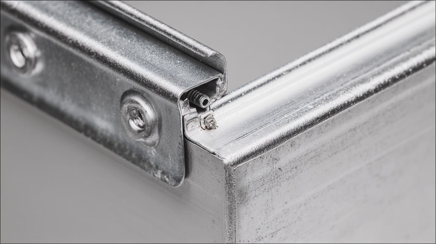
By the time I reach quotation review or design approval, I do not want bonding to remain a vague hope.
I want a few direct answers.
This does not need a long meeting. It does not need fancy language either. A short checklist often tells me whether the design has been thought through or just carried forward on assumption.
One clue I take seriously is this: if nobody can explain the intended bonding path in one clear sentence, the design is probably relying on luck.
Questions to Ask Before Approving a Design
When I review an enclosure, these are the types of questions I ask first:
- Where is the main bonding path?
- Is that path deliberate or accidental?
- Are coatings blocking conductivity?
- Is the contact area wide enough for the application?
- Will the path stay stable after vibration or service?
- If one joint gets worse over time, is there any redundancy?
I do not ask these questions to make the project slower. I ask them because vague bonding plans often become very slow later.
Red Flags in Supplier Designs
Some warning signs show up again and again.
If I hear any of the following, I become more careful:
| Red Flag | Why It Worries Me |
|---|---|
| “The screws will handle grounding.” | No detail, no proof |
| No note about surface finish impact | Conductivity risk is being ignored |
| No defined contact zone | Assembly may depend on chance |
| No seam continuity check | EMC risk is being postponed |
| No mention of service life | Reassembly may break the concept |
I have learned that weak bonding language often sounds casual. That is exactly why it slips through.
Simple Improvements That Make a Big Difference
The good news is that many bonding problems do not need giant redesigns.
Small changes often help a lot:
- add one dedicated grounding point
- define a bare contact zone
- use the right hardware at the right interface
- add a strap on removable parts
- note bonding requirements clearly on the drawing
- verify seam continuity before approval
I like these improvements because they are practical. They do not depend on optimism. They make the design clearer for engineering, purchasing, production, and testing.
A Buyer’s Mindset That Helps
If I were buying an enclosure from a factory, I would not ask only, “Can you make this?”
I would also ask, “How are you ensuring bonding after finishing and assembly?”
That question changes the quality of the conversation right away. It forces the supplier to talk about method, not just confidence.
And that matters, because good enclosure work is not only about cutting and drilling aluminum well. It is also about thinking clearly about the details that can quietly ruin performance.
That brings me to the final point, and it is the reason I feel strongly about this topic at all.
Conclusion
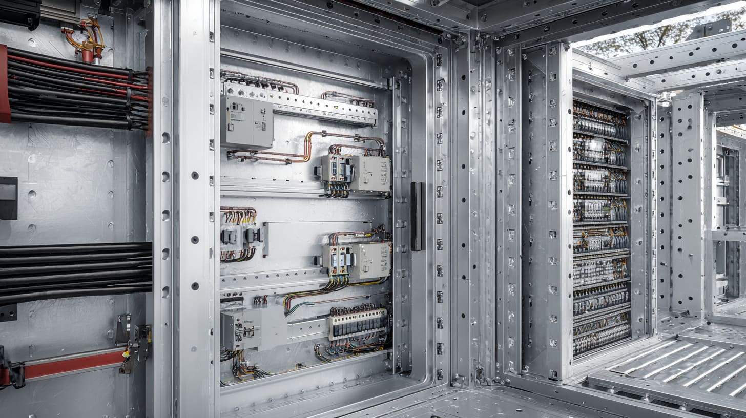
I do not avoid screw-only bonding because I like adding parts or making designs more complicated.
I avoid it because I have seen what happens when people expect a fastener to solve an electrical problem it was never carefully chosen to solve. The enclosure still looks finished. The screws still feel tight. The product still appears professional. But under coating, vibration, EMC pressure, humidity, or repeated service, that confidence can collapse very quickly.
That is why my view is simple: a screw is a mechanical helper first. It may support bonding in the right design. It should not automatically become the whole bonding strategy.
My opinion comes from how these projects behave in real work. I have watched weak bonding hide inside beautiful samples. I have watched teams lose time because the contact looked good but behaved badly. I have watched “small” assumptions turn into EMC problems, unstable grounding, and unnecessary redesign.
So I do not judge bonding by appearance. I judge it by stability.
I do not ask whether the metal parts touch once. I ask whether they will keep touching electrically in a reliable way after finishing, assembly, transport, use, and maintenance. That is a much harder question. It is also the right one.
If bonding matters for safety, EMC, or long-term reliability, I believe it deserves its own design logic. It deserves defined contact areas, proper hardware choices, and validation that matches real use. Anything less is often just borrowed confidence.
If you are reviewing an aluminum enclosure now and the bonding plan still sounds like “the screws should be enough,” I would stop there and check again before tooling or testing moves forward.
If you want, you can send me your enclosure drawing, assembly structure, or surface finish details. I can help you review whether the current bonding method is really safe to trust, or whether the design needs a better path before the problem becomes expensive.