Skip to content
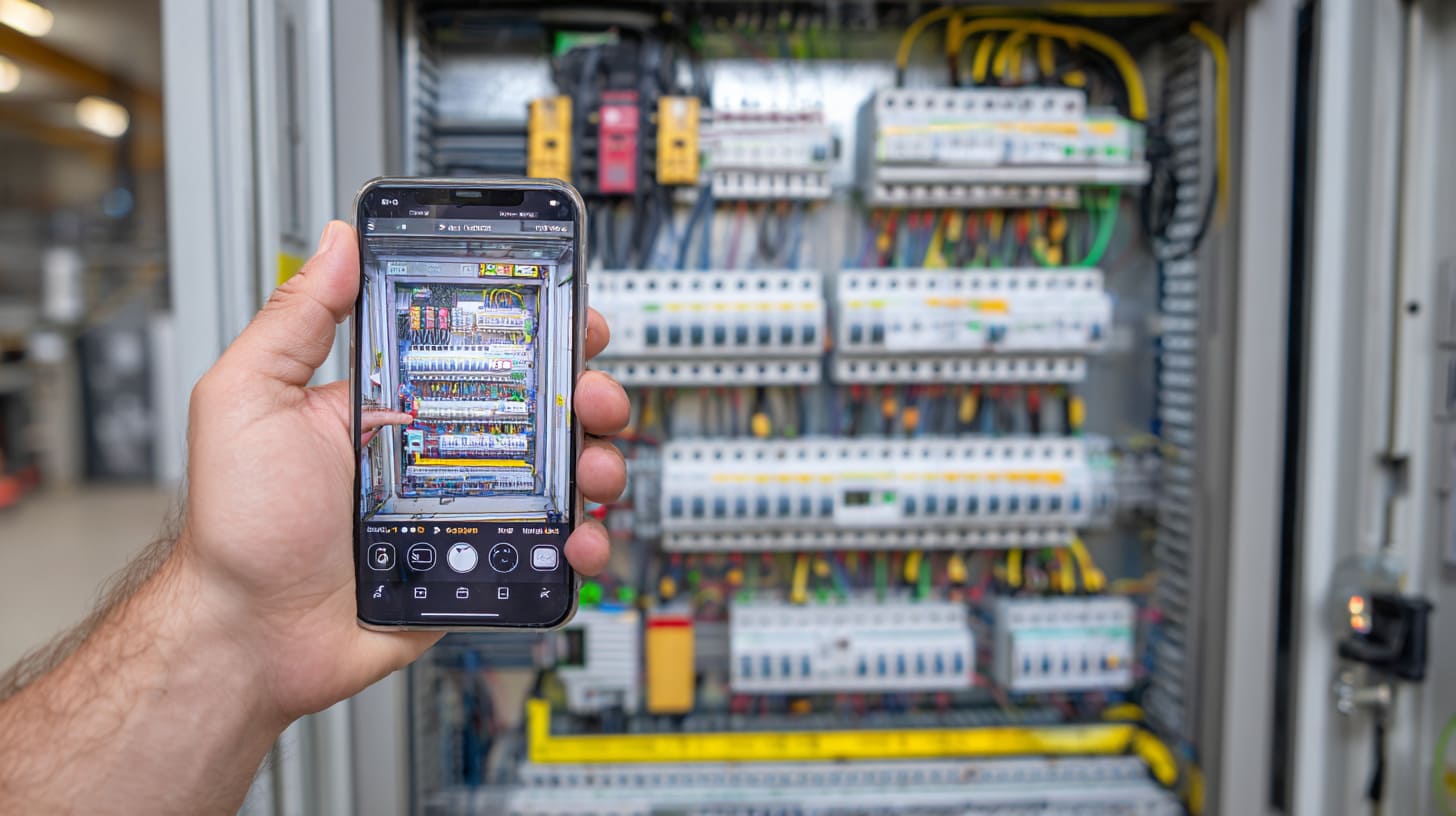
My phone pinged while I was checking a batch of enclosure samples on the shop floor. It was a short message from Davide in Finland. No greeting. Just one photo.
A control cabinet door was open. Inside, there was a PLC, a power supply, some terminals, and a wiring layout that looked… almost right. Almost.
He wrote: “Vincent, the PLC resets sometimes. We changed the sensors. Still happens. What should I check?”
That message is more common than people think. A PLC is not “just a controller.” It is the brain of the system. When it glitches, the whole machine feels unreliable. The scary part is this: the root cause is often not the PLC brand. It is the electrical design around it. Power noise. Heat. Grounding. Layout. Enclosure choice.
So in this guide, I’m going to break PLC down in a simple way. I’ll explain what a PLC is in electrical engineering, how the PLC working principle actually works, what scan time means, and how PLC vs relay control compares in real life. I’ll also share the things I watch for when my customers ask me to build custom enclosures around PLC systems.
If you are an engineer, an OEM buyer, or a project owner, this will save you time. And maybe save you one painful email thread later.
What Is PLC in Electrical Engineering?
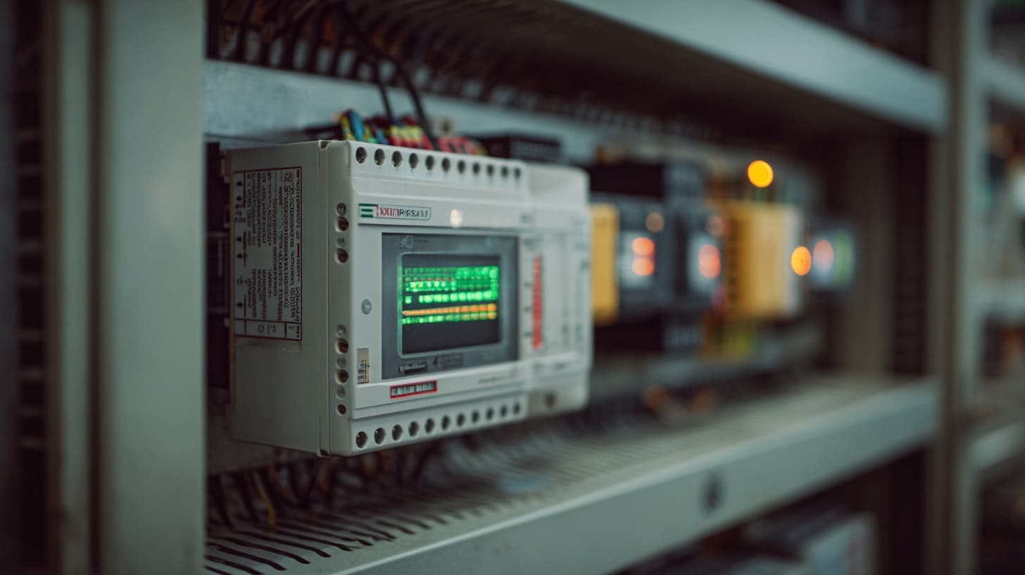
When people ask me “What is a PLC?” I usually answer with a question back:
“Do you want the textbook answer, or the answer that helps you stop downtime?”
Because both matter.
Schema-Friendly Definition
PLC (Programmable Logic Controller) is a rugged industrial computer used in electrical engineering to monitor inputs, execute programmed logic, and control outputs in real-time automation systems.
That definition is clean. But it does not show the feeling of it.
A PLC is like a calm supervisor on a factory line. It does not sleep. It listens to signals. It decides what to do. Then it sends commands out to the real world.
What Does PLC Mean in Electrical Systems?
In practical electrical systems, a PLC is built for three jobs:
- Read signals from sensors and switches
- Think using a program (logic rules)
- Act by turning outputs on and off, or sending analog signals
And it is built for ugly conditions. Heat. Vibration. Dust. Electrical noise. A normal office PC would cry in that cabinet.
Here’s a quick “human” view that I often share with buyers:
| Item | PLC | Office PC |
|---|---|---|
| Job | Real-time control | General computing |
| Environment | Harsh industrial | Clean office |
| Timing | Deterministic | Not guaranteed |
| Failure cost | Stops production | Annoying restart |
PLC in Electrical Engineering vs Traditional Relay Control
I still respect relay control panels. They taught the whole industry how logic works.
But relay control has a physical truth you cannot escape: every logic change is a wiring change.
That means:
- More wiring time
- More places to make mistakes
- More difficulty when you need to upgrade
With PLCs, the logic lives in software. Wiring is still important, but logic is easier to change and test.
Another small thing people ignore: PLCs make troubleshooting faster. A relay panel can feel like a jungle of wires. A PLC system often gives you status lights, diagnostics, and error codes.
That doesn’t mean PLCs are always “better.” It means PLCs are often the best tool when the system has complexity, changes, or scale.
And that leads us to the next topic, because most confusion starts with one phrase:
“How does the PLC actually work?”
PLC Working Principle Explained
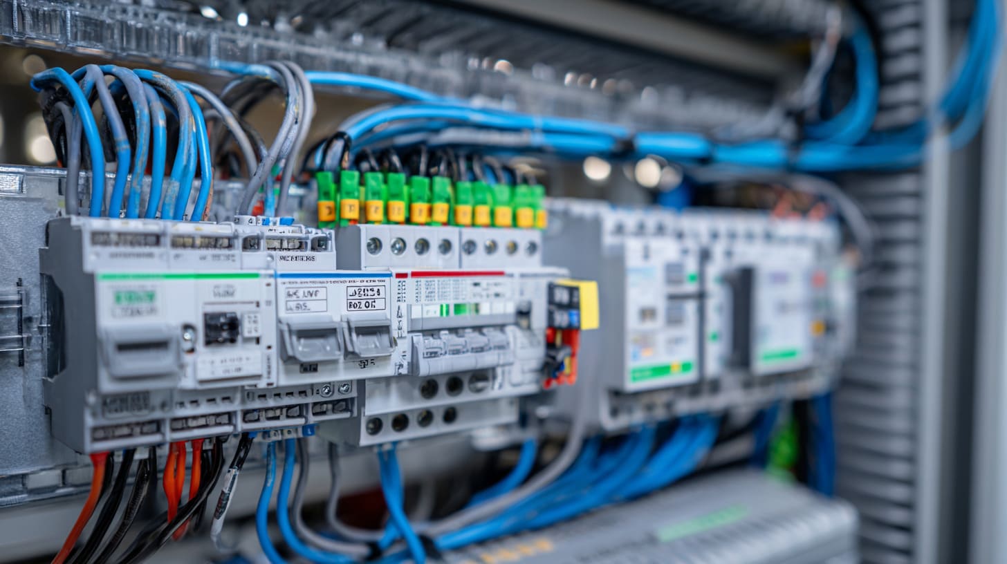
If you ever watched a machine “hesitate” for half a second, you already felt the PLC working principle, even if you didn’t know the name.
A PLC is basically running the same loop again and again, like a drummer keeping time.
Schema-Friendly Working Principle
The PLC working principle is based on a continuous scan cycle: the PLC reads input signals, processes logic in the CPU, updates outputs, and repeats this cycle in milliseconds.
That loop is the heartbeat.
PLC Scan Cycle Process
Most PLCs run in a repeating scan cycle:
- Input Scan
- Program Execution
- Output Update
- Internal Diagnostics
This order matters.
It means the PLC does not “see” changes in real time like a human eye. It sees changes at scan boundaries. That is why scan time matters in fast systems.
Signal Flow in a PLC System
I like to explain the signal flow like a simple chain:
- Sensors send signals to input modules
- CPU executes programmed logic
- Output modules control motors, valves, and actuators
But here’s the critical thinking part.
A PLC does not control the real world directly. It controls through hardware layers. And those layers can cause trouble.
For example:
- A weak power supply can cause input noise
- Poor grounding can create false triggers
- Long cable runs can pick up interference
- Bad panel layout can inject noise into analog signals
So when a customer tells me, “Our PLC is unstable,” I don’t start by blaming the PLC. I start by asking: What is the electrical environment around it?
What Is PLC Scan Time?
PLC scan time is the total time required for the controller to complete one full input-process-output cycle. It is typically measured in milliseconds.
Typical ranges people mention:
- Small PLCs: 1–10 ms
- Larger PLCs: 10–50 ms or more depending on program complexity
- Faster scan time improves response in high-speed automation systems
But here’s the real-life version I tell Davide:
If your machine is slow, scan time may not matter.
If your machine is fast, scan time can be the difference between “smooth” and “weird.”
A simple example of why scan time matters
Let’s say a sensor changes state for only 3 ms.
If your PLC scan time is 20 ms, it might never catch that signal.
So you get missed counts. Missed triggers. Random errors.
This is why high-speed systems use:
- High-speed counters
- Interrupt inputs
- Specialized modules
- Or different control architectures
A PLC is strong, but you still need to match it to reality.
And now we should talk about the PLC body itself, because the “brain” is not one part. It is a full system.
Main Components of a PLC System
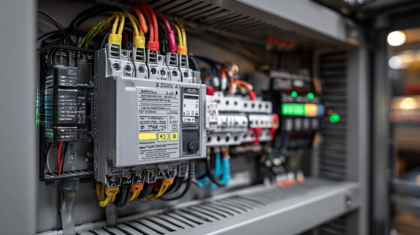
A PLC system looks clean in a catalog. But in a cabinet, it becomes a living ecosystem. Power. Modules. Wiring. Heat. Ground. Communication.
I’ve seen cabinets that look “professional” from far away, but inside, the power and signal lines are tied together like noodles. Then people wonder why the PLC acts strange.
So let’s break the parts down.
Power Supply
The power supply is often the quiet troublemaker.
- Converts AC/DC input to internal operating voltage
- Industrial-grade protection
In real projects, problems usually come from:
- Loose terminals
- Wrong voltage range
- Voltage dips when motors start
- Bad separation between noisy loads and control power
I once saw a PLC “random reset” issue that was solved by moving the power supply wiring away from a VFD cable. That was it. No PLC replacement. Just layout.
CPU (Central Processing Unit)
- Executes logic
- Manages memory and communication
- Determines overall system speed
The CPU is where scan cycle timing lives. The bigger the program and data, the more time it needs.
Here’s a small buyer-side table I use:
| CPU Spec | What it affects in real life |
|---|---|
| Program memory | How complex your logic can be |
| Data memory | How much you can log, buffer, store |
| Processing speed | Scan time, response time |
| Communication capacity | How many devices you can talk to |
Input Modules
- Digital inputs (ON/OFF)
- Analog inputs (0–10V, 4–20mA)
Digital inputs are like “yes/no.”
Analog inputs are like “how much.”
Critical thinking point: analog signals are sensitive.
They hate noise. They hate messy wiring. They hate poor grounding.
Output Modules
- Relay outputs
- Transistor outputs
- Triac outputs
Each output type has a personality:
| Output type | Best for | Watch out for |
|---|---|---|
| Relay | Mixed loads, simple control | Slower switching, mechanical wear |
| Transistor | Fast DC switching | Only DC loads, heat handling |
| Triac | AC loads | Leakage current, heat |
Communication Interfaces
- Ethernet/IP
- Modbus
- Profibus
- CAN
Communication is where systems become “smart.” And also where they become “fragile” if you do it without planning.
If you mix protocols, adapters, and long cable runs without structure, you get intermittent faults. Those are the worst faults. Because they waste weeks.
PLC Enclosure Considerations
Now this is my home field. Enclosures decide whether your PLC lives comfortably or lives under stress.
Key points I look at:
- EMI shielding
- Thermal management
- IP or NEMA rating selection
- Proper grounding
Here’s a simple table I often share with OEM buyers:
| Enclosure factor | What can happen if it’s wrong |
|---|---|
| Heat trapped inside | PLC resets, I/O drift, shorter lifespan |
| Poor EMI shielding | false inputs, communication drops |
| Wrong IP/NEMA rating | dust or moisture damage |
| Bad grounding | noise, unstable signals, safety risk |
This is also why I always ask for installation environment before quoting enclosure work. Indoor? Outdoor? Near VFDs? Near welding? Those details change the design.
Now, PLCs come in different shapes and scales. And choosing the wrong type can hurt cost and reliability.
Types of PLCs Used in Electrical Systems
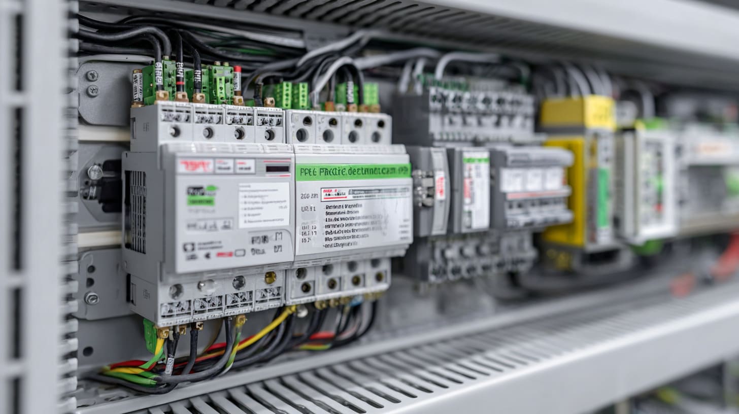
When John from Hungary first started his project, he wanted a “small PLC.” He thought small means cheap, and cheap means safe for a new project.
That logic is normal. It is also incomplete.
Because “small” can also mean limited expansion, limited communication, and painful redesign later.
Compact PLC
- Fixed I/O
- Small machinery
Best for:
- Simple machines
- Small automation tasks
- Tight cabinet space
Risk:
- You may outgrow it fast
Modular PLC
- Expandable I/O
- Medium automation systems
This is the “balanced” choice for many projects. You add modules as needed.
Rack-Mounted PLC
- High I/O capacity
- Large industrial plants
This is for bigger systems where you want more power, more communication, and a clean architecture.
Safety PLC
- Redundant processors
- SIL compliance
Safety PLCs exist because “normal PLC logic” is not enough for safety standards.
Critical thinking point:
Safety is not only about the PLC type. It is also about system design, wiring, and how you handle failure modes.
I’ve seen people buy a safety PLC, then mount it in a cabinet with poor airflow and messy wiring. That is like buying a helmet but riding with eyes closed.
Now, the question everyone asks in meetings:
“Is PLC better than relay control?”
Let’s talk about that like adults. Not like sales brochures.
PLC vs Relay Control: Which Is Better?
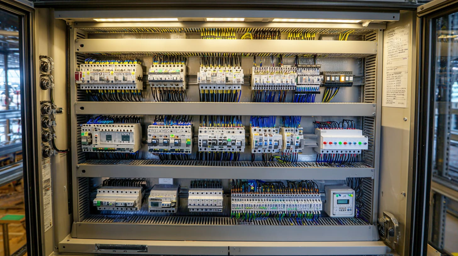
In many factories, relay control still runs quietly for decades. No software. No laptop. Just wires, contacts, and logic you can see.
So why did PLCs take over?
Because modern systems change. And relay systems hate change.
PLC vs Relay Control Comparison
| Feature | PLC | Relay Control |
|---|---|---|
| Flexibility | Reprogrammable | Hardwired |
| Wiring Complexity | Low | High |
| Maintenance | Easier diagnostics | Manual tracing |
| Scalability | Easy expansion | Limited |
| Initial Cost | Higher | Lower |
| Long-Term Cost | Lower | Higher |
That table looks clean. But reality is messy.
Are PLCs Better Than Relays?
In most industrial applications, PLCs are better than relays because they:
- Reduce wiring complexity
- Allow easy logic modification
- Improve troubleshooting speed
- Increase long-term reliability
However, simple systems with minimal logic may still use relay control for cost reasons.
Here’s my honest opinion from projects I’ve seen:
- If the logic is simple and will never change, relays can be fine.
- If the logic may change, PLC wins.
- If you need data, alarms, remote monitoring, PLC wins.
- If your team hates programming, relay can feel safer.
And that last point is important.
A PLC is only “better” when the people and process support it. Otherwise, you end up with a machine that nobody knows how to maintain.
Now let’s widen the lens, because PLC is not the only control technology in the room.
PLC vs DCS vs Microcontroller
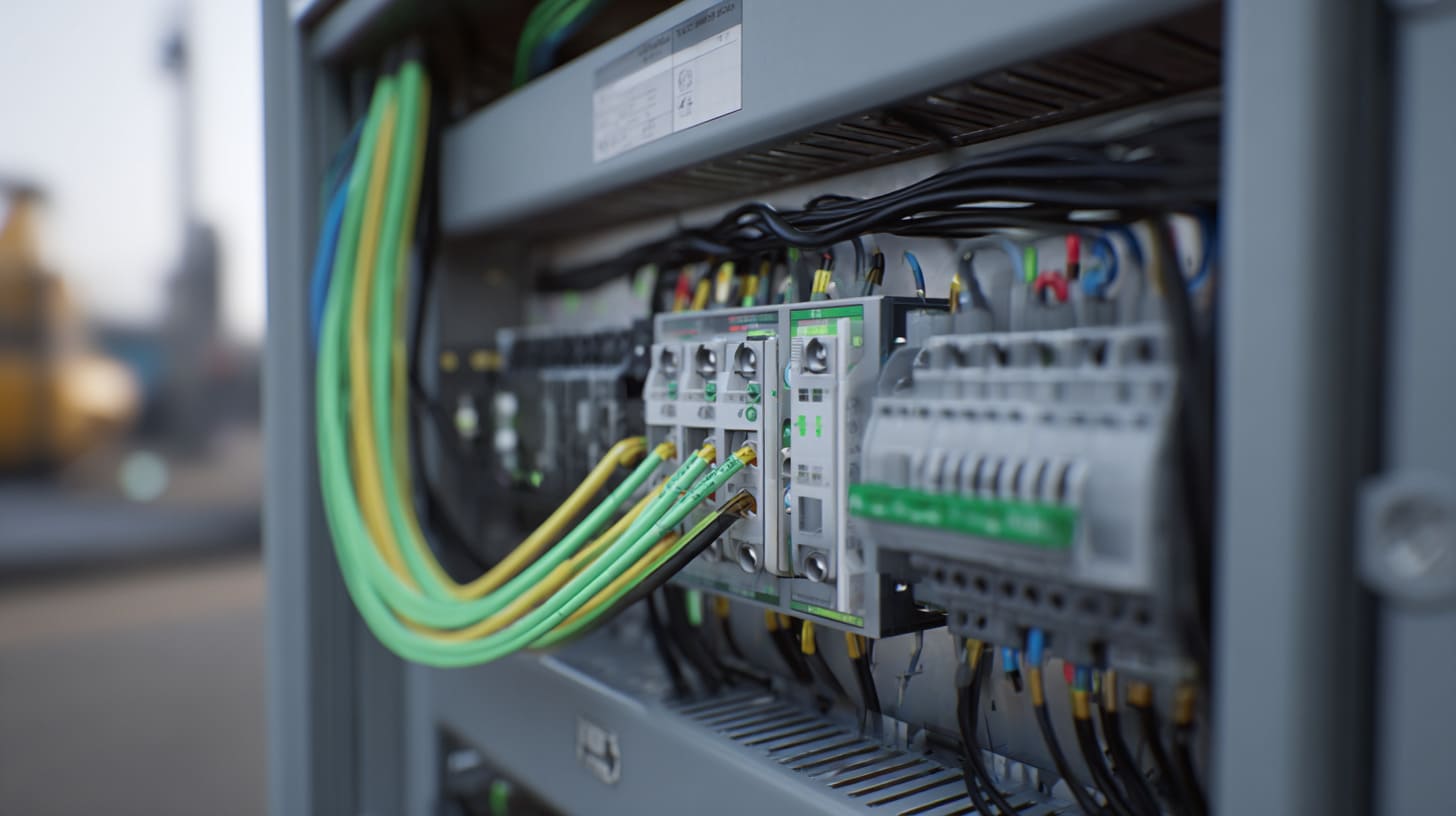
Sometimes buyers ask me: “Vincent, should we use PLC or microcontroller? Or should we go DCS like big plants?”
That question is healthy. It means you are thinking about scale and cost, not just copying old decisions.
PLC vs DCS
- PLC: Ideal for machine-level control
- DCS: Best for large-scale process control
DCS is built for process plants. Think chemical lines, refinery logic, big distributed systems.
PLC is built for machines and automation lines where you want tight control and fast response.
PLC vs Microcontroller
- PLC: Industrial-grade, standardized, robust
- Microcontroller: Embedded, product-level control
Microcontrollers are great when you want a custom embedded product. Small boards. Low cost per unit. Tight integration.
But microcontrollers need more design work. More firmware work. More testing. More time.
When to Choose PLC
- Industrial machinery
- Manufacturing lines
- Electrical panel automation
Here’s a quick decision table:
| Control type | Best fit | Common risk |
|---|---|---|
| PLC | Industrial machines | poor wiring / noise issues |
| DCS | Large process plants | high complexity and cost |
| Microcontroller | Embedded products | long dev cycle, support burden |
I always tell buyers: don’t choose based on pride. Choose based on what you can build, maintain, and scale.
Now, where do PLCs actually show up? Not just in textbooks, but in places where money and safety are on the line.
Where Are PLCs Used?
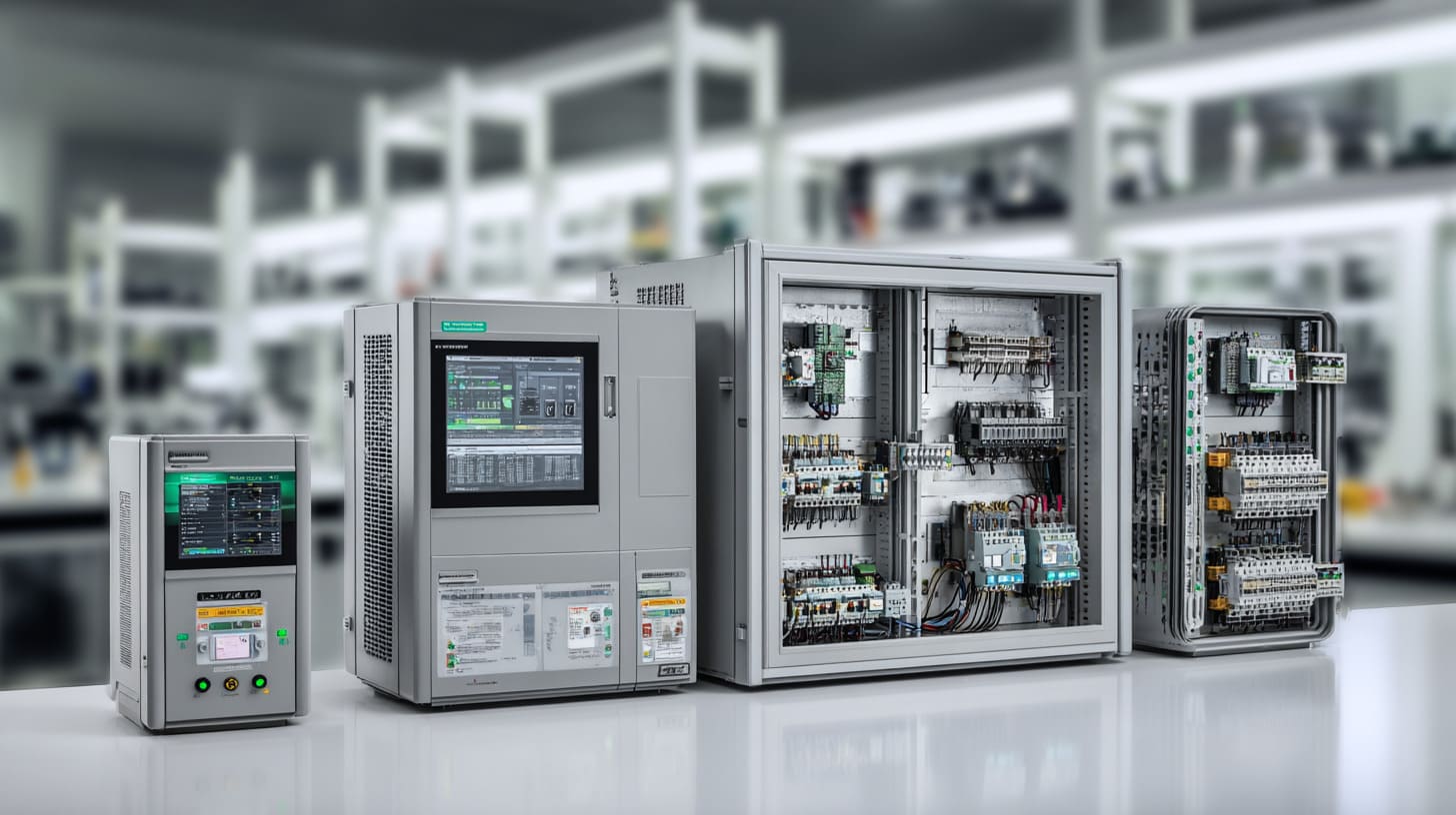
If you walk around a real factory, you’ll see PLCs hiding in plain sight. They are not glamorous. They are quiet. But they are everywhere.
Manufacturing Automation
- Conveyor systems
- Robotic lines
This is classic PLC territory. Fast decisions. Many sensors. Many outputs.
Electrical Power Systems
- Substation control
- Generator synchronization
Here, reliability is everything. You can’t “just reboot” a power system and laugh.
HVAC and Building Systems
- Temperature control
- Energy monitoring
This area is growing fast because energy cost is not a small problem anymore. Building automation is getting smarter.
Water Treatment Plants
- Pump automation
- Level control
This is where I see some of the harshest environments. Moisture. Corrosion risk. Long cable runs. Outdoor panels.
And that leads to the next question that buyers always ask me:
“How long will this PLC last?”
How Long Do PLCs Last?
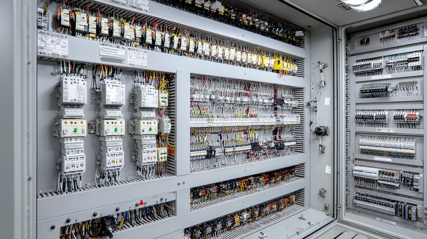
If you’re an OEM buyer, lifespan is not a “nice to know.” It’s a cost model.
A PLC replacement is not just a part cost. It is downtime, labor, and customer trust.
Schema-Friendly Answer
A properly installed PLC typically lasts 10 to 20 years depending on environmental conditions, load cycles, and maintenance practices.
That range surprises new buyers. They expect “electronics = short life.” But industrial PLCs are built to survive.
Factors Affecting PLC Lifespan
- Heat exposure
- Electrical noise
- Power quality
- Ventilation and enclosure design
In my experience, heat is the biggest quiet killer. Heat does not break things fast. It breaks them slowly. Then one day, you get a reset. Or a weird analog drift. Or a module failure.
Extending PLC Life
- Use proper grounding
- Select correct enclosure rating
- Maintain stable power supply
- Perform periodic inspection
Here’s a small “lifespan protection checklist” I use in enclosure design reviews:
| Risk | What I do about it |
|---|---|
| High cabinet temp | add vents, fan, heat spacing |
| VFD noise | separate wiring, shield, grounding |
| Moisture/dust | match NEMA/IP rating |
| Loose terminals | correct torque and inspection routine |
And here’s the story part:
I’ve seen a cheap cabinet design cut PLC life by half. Same PLC. Same brand. Different enclosure environment. It’s like putting a healthy person in a room with no air. They won’t die today, but they won’t stay strong.
Now, when you pick a PLC, you also need to match it to your project needs. That choice decides your cost and your future headaches.
How to Choose the Right PLC for Your Electrical Project?
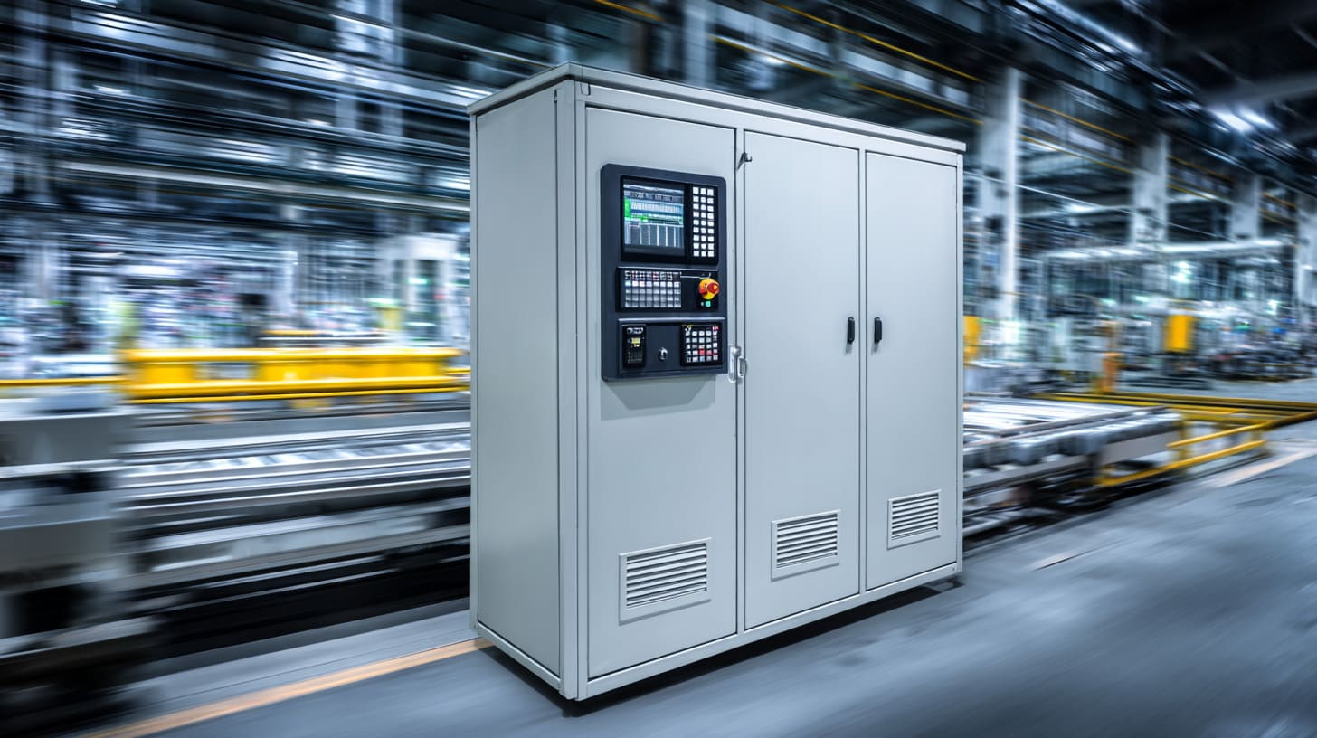
When Davide asks me for advice, I never start with brand names. I start with questions.
Because “best PLC” is not a fixed thing. It depends on what you need now, and what you might need later.
Determine I/O Count
- Digital inputs/outputs
- Analog signals
- Future expansion buffer
I always suggest adding a buffer. If you think you need 32 inputs, consider 40. Growth happens.
Evaluate Communication Needs
- SCADA integration
- Remote monitoring
If you plan remote monitoring, protocol matters. Communication modules cost money, but changing architecture later costs more.
Environmental Conditions
- Temperature
- Dust
- Moisture
Critical thinking point:
Sometimes the real environment is worse than people admit. A cabinet “indoors” might still face oil mist, vibration, and temperature swings.
Processing Requirements
- Scan time requirements
- Data logging capability
If you have fast moving parts, scan time matters. If you need traceability, memory and logging matter.
Compliance Requirements
- UL
- CE
- IEC standards
Compliance is not paperwork. It affects component selection, wiring rules, and enclosure design. If you ignore it early, you pay later.
Here’s a practical selection table:
| Requirement | What to check |
|---|---|
| Many sensors | I/O capacity and expansion |
| Fast triggers | scan time, high-speed inputs |
| Remote monitoring | Ethernet and protocol support |
| Harsh environment | temperature rating, enclosure rating |
| Safety needs | safety PLC, SIL requirements |
Now let’s talk about the part people love to skip until something fails: installation practices.
PLC Installation Best Practices

I’ve seen expensive PLC systems fail because someone treated wiring like “just connect it.”
But wiring is not decoration. Wiring is performance.
Proper Grounding
- Reduce electrical noise
- Prevent signal interference
Bad grounding is like bad sleep. You can still function, but you are always tired and unstable.
A simple habit I recommend:
- One grounding strategy
- Clear grounding points
- No “random ground here, random ground there”
Heat Management
- Ensure airflow
- Avoid overheating inside enclosure
If a cabinet feels warm when you touch it, I get nervous. Because inside, it is hotter.
Basic heat habits:
- Leave space around modules
- Avoid packing components too tight
- Add airflow or heat sinks when needed
Cable Segregation
- Separate power and signal lines
- Prevent cross-interference
This is where many “random faults” are born.
I like a simple rule:
- Power cables on one side
- Signal and communication cables on the other side
- Cross them only at 90 degrees when needed
Here’s a quick “panel wiring hygiene” table:
| Wiring mistake | Result you will see |
|---|---|
| Power + signal tied together | false inputs, noise, unstable analog |
| VFD cable near I/O | random resets, comm drops |
| Poor terminal torque | intermittent faults |
| No separation zones | troubleshooting nightmare |
And now, the questions I hear the most on calls, in emails, and during late-night project chats.
FAQ: PLC in Electrical Engineering
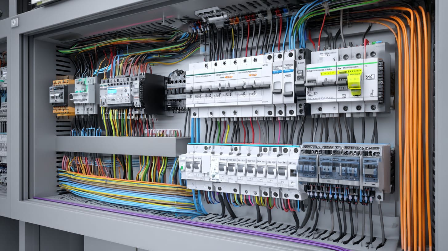
What Is PLC Scan Time?
PLC scan time is the duration required to read inputs, execute logic, and update outputs once. Faster scan times allow more responsive automation systems.
If your machine moves fast, scan time becomes a design spec, not trivia.
How Long Do PLCs Last?
Most industrial PLCs operate reliably for 10–20 years when installed in proper electrical enclosures and maintained correctly.
In my opinion, most early failures are not “PLC problems.” They are environment problems.
Are PLCs Better Than Relays?
Yes, for most modern automation systems. PLCs offer flexibility, easier troubleshooting, scalability, and reduced wiring compared to relay-based control panels.
But if you only need one simple logic function and it will never change, relay control can still be a valid choice.
What Is the PLC Working Principle Explained Simply?
A PLC reads input signals, processes programmed instructions, and controls output devices in a continuous loop called the scan cycle.
It’s like breathing. Inhale inputs. Think. Exhale outputs. Repeat.
And if you remember nothing else from this article, remember this: the PLC is the brain, but the cabinet is the body. If the body is weak, the brain will suffer.
Conclusion

A PLC in electrical engineering is not just a “controller.” It is the decision engine behind modern automation. It reads signals, runs logic, and drives outputs in a tight scan cycle. That is the PLC working principle in plain words.
But the PLC itself is only part of the story. The power supply, wiring layout, grounding, heat handling, and enclosure design often decide whether the system feels stable or “random.”
If you are choosing between PLC vs relay control, I’d keep it simple:
- Use relays when logic is minimal and fixed
- Use PLCs when logic grows, changes, or needs diagnostics and scalability
If you’re working on a PLC cabinet or an OEM control box and you want fewer surprises, I’m happy to help you review the enclosure and integration details. You can share your drawing, environment, and I/O list, and I’ll tell you what I would change before you build the first batch.
If you want to talk, you can reach me through my website or email. The fastest way is usually to send one clear photo of the cabinet layout and your main concern. I’ve seen enough “almost right” panels to know where problems like to hide.