Skip to content
A device can look excellent on the screen and still fail in the real world for one very small reason.
I have seen that happen more than once.
A customer sent me an aluminum enclosure drawing for an industrial control product. The cutouts were clean. The logo position was fixed. The surface finish looked good. The inner layout made sense. Everyone felt relaxed. Then the sample went into EMC testing, and the result was ugly. The product did not fail because the board was bad. It did not fail because the shell was weak. It failed because the grounding path was not handled well, and the bonding between metal parts was not stable enough.
That kind of problem is frustrating because it hides so well.
From far away, grounding and bonding sound like simple electrical terms. Many designers think they can deal with them later. Many buyers assume the factory will “just know” what to do. Many engineers mix safety grounding, chassis grounding, and signal grounding into one blurry idea. Then the project reaches testing, assembly, or field use, and the confusion becomes expensive.
I do not treat grounding and bonding as side details anymore. I treat them as part of product structure, part of compliance, and part of risk control.
To me, this is where many enclosure projects quietly go wrong: the drawing shows shape, size, and cutouts clearly, but it says almost nothing about how electricity will move, where fault current will go, or how metal parts will stay at the same potential.
In this article, I want to explain grounding and bonding in plain language. I want to connect theory with real enclosure work. I also want to show where designers, OEM buyers, and custom enclosure suppliers often misunderstand each other. That gap matters. It can cost time, money, and trust.
Before I get into standards and hardware choices, I need to make one thing simple first: what grounding and bonding really mean when we stop speaking like a textbook.
What Are Grounding and Bonding in Simple Terms?
I think many people get lost here because the words sound familiar, but the actual job of each one is different.
Grounding usually means connecting a system to a reference point called ground. In many cases, that means earth ground for safety. In some cases, it means a functional reference for the circuit. Bonding means connecting metal parts together so they stay at the same electrical potential. These two ideas are related, but they are not the same.
The basic definitions designers actually need
I like to keep the definitions practical.
| Term | Simple meaning | Main purpose | Common example |
|---|---|---|---|
| Grounding | Connecting a circuit or system to a reference ground | Safety, stability, noise control | Power supply earth connection |
| Bonding | Connecting conductive parts together | Equal potential, safety, shielding | Enclosure panel bonded to frame |
| Earth ground | Direct connection to earth or protective ground | Shock protection | PE wire in AC-powered equipment |
| Chassis ground | Metal body used as a reference or shield path | EMC and safety support | Metal enclosure tied to system ground |
| Signal ground | Circuit return reference | Stable signal behavior | PCB ground plane |
Grounding is about reference. Bonding is about connection between conductive parts.
That difference sounds small, but it changes design decisions.
For example, a metal enclosure may be bonded well from panel to panel, but if it is not grounded the right way, the system can still behave badly. On the other side, a system may be grounded to earth, but if separate metal panels are not bonded well, the enclosure can act like a broken shield.
Why they are often misunderstood
I often see three kinds of confusion:
- People mix safety grounding with noise control
- People treat chassis, earth, and signal ground like they are all one thing
- People assume any metal screw automatically creates a good electrical bond
That last one causes more trouble than many people expect.
A screw can hold two parts together very tightly and still give poor electrical continuity if there is anodizing, paint, oxide, or contamination between the surfaces.
The way I explain it to customers is simple: mechanical contact and electrical contact are not always the same thing.
A real-world analogy that helps
I sometimes compare this to water pipes in a building.
Grounding is like deciding where the main pressure reference is. Bonding is like making sure all the metal pipes are connected well so pressure does not become uneven from one section to another.
If one part is isolated, pressure behaves oddly. If one path is weak, the whole system becomes unstable. The same thing happens in electrical products. Voltage differences show up where people did not expect them. Noise finds easy places to travel. Testing becomes messy.
Another way to say it is this: grounding gives the system a known reference, and bonding helps the metal structure behave like one whole body instead of random separate pieces.
I usually know a designer truly understands this topic when they stop asking “Where do I put ground?” and start asking “What exactly am I trying to control here—safety, shielding, return path, or signal stability?”
That question leads to better products.
Now the next question is the one that really matters in business: why should a device designer care so much about this in the first place?
Why Grounding and Bonding Matter in Device Design
I have never seen a customer get excited about grounding lines on a drawing. People get excited about the housing shape, the logo, the color, the board function, the display, the launch date. That is normal. Grounding and bonding feel invisible.
But invisible does not mean unimportant.
These choices shape safety, EMC performance, signal quality, field reliability, and even project cost.
Safety: protecting users and equipment
The first reason is safety.
If a fault happens inside a device, current needs a safe path. That is where grounding becomes more than theory. It becomes protection.
A proper protective ground can help:
- Reduce electric shock risk
- Guide fault current away from the user
- Trigger protection devices faster
- Keep exposed metal parts from reaching dangerous voltage
This matters even more in metal enclosure products, industrial control boxes, power devices, and equipment used in rough environments.
| Safety issue | What grounding or bonding helps with | What can go wrong without it |
|---|---|---|
| Internal insulation failure | Fault current path | Metal shell becomes dangerous |
| Loose metal panels | Equal potential between parts | Touch voltage difference |
| AC-powered product | Protective earth connection | Higher shock risk |
| Mixed metal assemblies | Reliable conductive link | Unstable safety performance |
What makes this tricky is that many failures do not look dramatic in the factory. They show up later, in testing, field use, or maintenance.
EMC performance: passing compliance tests
This is the part that often hurts the project budget.
A product can function normally on the bench and still fail EMC testing because of grounding or bonding weakness. I have watched that happen to otherwise good designs.
A poor chassis bond can create:
- Weak shielding continuity
- More radiated emissions
- More conducted noise
- Unstable behavior near cables or connectors
A metal enclosure is not automatically a good shield. It becomes a useful shield only when its conductive path is continuous enough.
That is why panel joints, screw points, surface finish, and cable entry design matter.
From my side, I pay close attention to the path around seams and openings. A beautiful enclosure with too many electrically broken joints can become an expensive antenna.
Signal integrity in modern electronics
This part is often ignored by people who think only about safety.
Signal grounding affects the behavior of the PCB itself. If the reference is unstable, noise can enter sensitive circuits. Ground loops can appear. Small measurement errors can turn into annoying failures.
This becomes more important in:
- High-speed digital designs
- Sensor products
- RF devices
- Mixed analog and digital systems
- Products with communication ports and long cable runs
Sometimes the enclosure problem is not only the enclosure problem. The enclosure and PCB grounding strategy can fight each other.
I have seen designers blame the shell first, then blame the board, then blame the test lab. In the end, the problem was the relationship between all three.
Cost and reputation impact
People often think grounding mistakes are technical mistakes. I think they are also business mistakes.
Here is why:
| Problem | Direct cost | Hidden cost |
|---|---|---|
| EMC failure | Retest fee, redesign labor | Launch delay |
| Poor bonding point design | Rework in factory | Supplier friction |
| Late grounding change | New tooling or machining | Slower approval |
| Field noise issue | Returns or service calls | Brand damage |
The harder truth is this: poor grounding decisions often cost money in places that are not easy to track on one quotation sheet.
You may pay for:
- Extra engineering hours
- More sample rounds
- Delayed shipment
- Compliance retesting
- Unplanned hardware changes
- Lost confidence between buyer and supplier
When I judge project risk, I do not only ask whether the enclosure can be produced. I ask whether the grounding logic is clear enough to survive assembly, testing, shipping, and real use without becoming a quiet source of blame later.
Once that risk becomes clear, the next step is obvious: a designer needs to know the main types of grounding, not just the word “ground.”
Types of Grounding Every Designer Should Know
I think many design problems start because people use one word for four different jobs.
When someone says, “We need to ground it,” I always want to stop and ask, which kind? That question saves time.
Earth grounding (protective grounding)
Earth grounding is mainly about safety.
This is the protective ground connection used to direct fault current safely away from exposed conductive parts. It is common in AC-powered devices and equipment that must meet electrical safety requirements.
A protective earth connection is usually required when:
- The product has exposed metal parts
- The device uses mains power
- Safety standards call for it
- Fault conditions could energize the enclosure
| Aspect | Earth grounding |
|---|---|
| Main goal | User safety |
| Typical use | AC-powered equipment |
| Connected to | Protective earth / PE |
| Design concern | Low-resistance fault path |
| Common standards link | IEC, UL safety rules |
This is not optional in many products. It is a design duty.
Chassis grounding
Chassis grounding uses the enclosure or metal frame as part of the electrical reference or shielding structure.
This is very common in industrial devices, communication equipment, rack-mounted products, and metal control boxes.
The chassis can help:
- Control noise
- Improve shielding
- Create a stable enclosure reference
- Support cable shield termination
But it works only when the metal structure behaves as one conductive body.
I often see people assume that a metal enclosure naturally does this job well. It does not. The seams, fasteners, finishes, and interfaces decide that.
Signal grounding
Signal ground is the return reference for circuits.
This matters deeply on the PCB side. Sensitive analog sections, digital switching circuits, high-speed interfaces, and power returns all depend on stable reference behavior.
Designers often struggle with whether signal ground should be separated from chassis ground or connected to it. The answer depends on the product, the noise environment, the interface type, and the testing goal.
That is why blanket advice is dangerous.
| Question | Simple answer |
|---|---|
| Should signal ground always be isolated? | No |
| Should signal ground always connect directly to chassis? | No |
| Should the connection be planned deliberately? | Yes |
| Should one-point vs multi-point connection be reviewed by function? | Yes |
I get cautious when I see a drawing that shows beautiful mechanical detail but says nothing about where the signal ground meets the enclosure, because that missing sentence can turn a stable design into a noisy one.
Functional grounding
Functional grounding is used for performance, not mainly for shock protection.
This appears in products where grounding improves:
- EMC behavior
- RF performance
- Noise control
- Measurement stability
In these cases, grounding may not be strictly about safety rules. It may exist because the device performs better with that reference path.
Examples include:
- RF modules
- High-speed communication devices
- Sensitive measurement equipment
- Shielded connector interfaces
This is where many new designers get confused. They think if a ground is not “earth ground,” it must be less important. That is not true. Functional grounding can be critical for product success.
A simple comparison table
| Grounding type | Main purpose | Typical place | Main risk if ignored |
|---|---|---|---|
| Earth ground | Safety | AC-powered metal devices | Shock hazard |
| Chassis ground | Shielding and reference | Enclosure and frame | Poor EMC |
| Signal ground | Circuit reference | PCB and electronics | Noise and instability |
| Functional ground | Performance improvement | RF / high-speed systems | Weak operation quality |
Once a designer understands these types clearly, bonding starts to make more sense too. Because after deciding what kind of ground you need, the next question becomes how the metal parts will actually stay electrically connected in the real product.
Bonding Methods in Enclosure and System Design
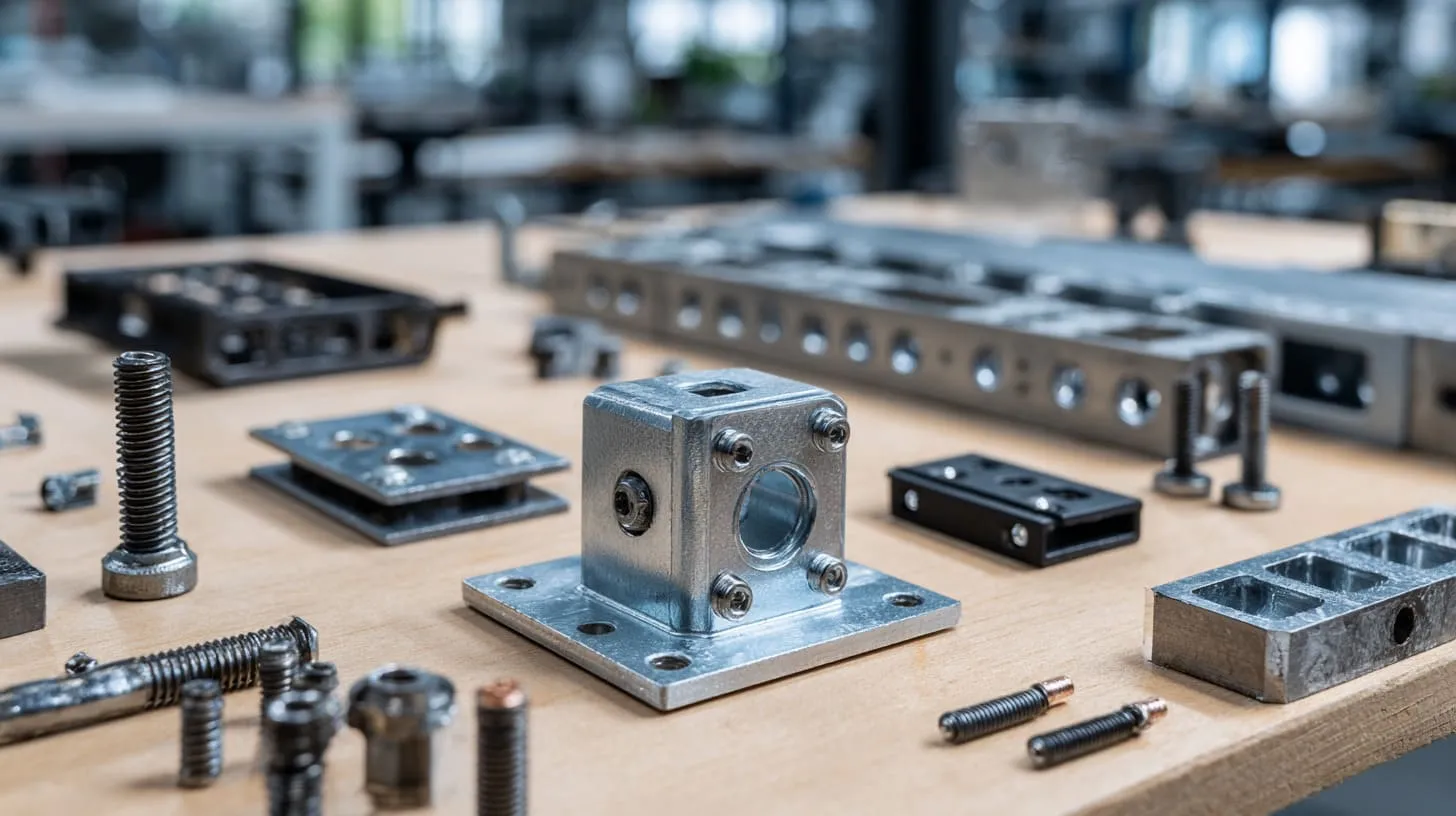
Bonding sounds simple on paper. Connect metal parts. Keep them at the same potential. Done.
In real work, it is not that neat.
Two parts can touch and still not bond well. Two parts can be electrically connected in the sample stage and then become unstable after coating, vibration, corrosion, or repeated assembly.
That is why I take bonding details seriously.
Metal-to-metal bonding techniques
The most common bonding methods in enclosure work include:
- Screws with proper contact surfaces
- Bonding studs
- Conductive fasteners
- Spot welding or seam welding
- Copper braid straps
- Metal clips or spring contacts
Each method has a place.
| Method | Good points | Weak points | Common use |
|---|---|---|---|
| Screws and fasteners | Easy, low cost, common | Surface finish can block contact | Panels, lids, brackets |
| Bonding studs | Clear fixed bonding point | Added hardware step | PE or chassis connection |
| Welding | Strong and reliable | Less flexible for service | Permanent frame bonding |
| Copper braid | Good for moving or removable parts | Extra material and labor | Doors, panels, hinged parts |
| Conductive clips | Useful in tight spaces | Needs careful fit | Shield parts and covers |
A simple screw is often enough mechanically. It is not always enough electrically.
That gap matters.
Surface treatment considerations
This is one of the most overlooked parts of the whole topic.
Anodizing, powder coating, and paint improve appearance and corrosion resistance. But they can also block electrical contact.
I work with aluminum enclosures often, so this issue comes up all the time.
If the design needs electrical continuity at a certain point, that area may need:
- Masking before anodizing
- Surface removal after coating
- Special conductive treatment
- A tooth washer or dedicated contact hardware
I get nervous when a drawing asks for full anodizing everywhere and also assumes perfect grounding through the same surfaces, because those two wishes often fight each other.
Use of conductive materials
Some bonding situations need more than bare metal contact.
That is where conductive support materials come in, such as:
- EMI gaskets
- Conductive foam
- Copper braids
- Conductive tape
- Shielding fabrics
- Bonding straps
These materials help when:
- A removable panel needs shielding continuity
- A door must stay bonded while opening and closing
- Small gaps affect EMC performance
- Mechanical movement makes rigid contact unreliable
| Material | Main job | Best use case |
|---|---|---|
| EMI gasket | Seal gaps electrically | Panel seams, doors |
| Conductive foam | Flexible contact | Light covers and shield areas |
| Copper braid | Reliable flexible bond | Hinged or moving connections |
| Bonding strap | Dedicated grounding path | Cabinet doors, heavy panels |
Designing for long-term reliability
A bond that works only in the lab is not good enough.
Real products face:
- Vibration
- Moisture
- Dust
- Corrosion
- Repeated service access
- Heat cycling
That means bonding must survive more than first assembly.
The point I usually test in my head is not “Will this conduct today?” but “Will this still conduct after shipping, assembly, coating variation, and one year of use?”
That is a harder question. It is also the right one.
A practical design view
Here is a quick way I judge bonding options:
| Design condition | Bonding choice I lean toward |
|---|---|
| Fixed internal frame | Screw or welded bond |
| Hinged panel or door | Copper braid or flexible strap |
| EMC-sensitive seam | Conductive gasket plus mechanical fastening |
| Coated aluminum panel | Masked contact zone plus conductive fastener |
| Repeated maintenance area | Defined bonding hardware, not accidental contact |
Bonding becomes even more important when the enclosure material is aluminum, because aluminum is helpful in many ways, but it also creates its own quiet problems.
Grounding and Bonding in Aluminum Enclosures
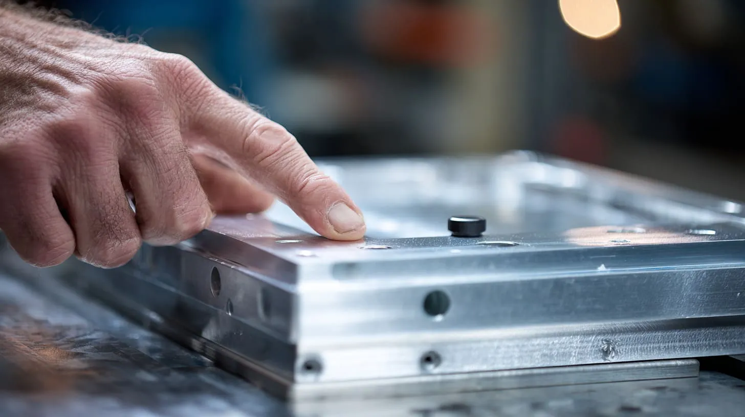
I work with aluminum enclosures a lot, so I know both sides of the story.
Aluminum is light. It machines well. It looks clean. It works nicely for custom projects. It can also become annoying when grounding and bonding are not planned early.
The reason is simple: aluminum is conductive, but the real surface condition often gets in the way.
Challenges with aluminum materials
Aluminum forms an oxide layer naturally. That layer can reduce conductivity at the contact point. Then many projects add anodizing, which makes the problem even more obvious.
So even though the material itself is conductive, the finished part may not give reliable electrical continuity where you need it.
Common problems include:
- Oxide layer at contact surfaces
- Anodized surfaces acting like insulation
- Inconsistent bonding across removable panels
- Weak continuity through coated screw joints
| Aluminum enclosure issue | Why it matters |
|---|---|
| Natural oxide film | Reduces direct conductive contact |
| Anodized finish | Blocks bonding at contact area |
| Powder-coated panel | Prevents electrical continuity |
| Removable lid | May lose repeatable bond after servicing |
This is why aluminum enclosure projects need more deliberate grounding detail than many people expect.
Practical solutions for designers
The good news is that the fixes are usually not mysterious.
They just need to be specified clearly.
Useful methods include:
- Mask grounding points before anodizing
- Add grounding studs
- Use conductive washers
- Define bare metal contact zones
- Add bonding straps for removable sections
- Include continuity check in QC
| Solution | What it solves | Best time to decide |
|---|---|---|
| Masked contact area | Allows real metal contact | Drawing stage |
| Grounding stud | Creates fixed grounding point | Mechanical design stage |
| Conductive washer | Breaks through light surface layer | Hardware selection stage |
| Bonding strap | Keeps continuity on moving part | Assembly design stage |
| Continuity test | Confirms result in production | QC planning stage |
I prefer a design that shows one intentional grounding point over a design that “probably works” through random screws. Random contact creates random results.
A case from real work
One enclosure project stays in my mind because the failure looked so unfair at first.
The customer had a clean aluminum case with front and rear panels, a removable lid, and good internal board support. The product worked well in normal use. But during EMC review, emissions were not where they should be. Everyone first looked at the PCB and cable layout.
The real issue turned out to be the lid bonding.
The lid was anodized. The contact path around the seam was weak. The screws held the lid tightly, but the electrical continuity around that joint was not stable enough for shielding performance.
We did not redesign the whole product. We only changed a few details:
- masked key contact points
- adjusted hardware
- improved contact at the seam
That small fix saved a much larger redesign.
A lot of enclosure problems feel dramatic in the meeting room. Many of them are actually detail problems hiding inside ordinary structures.
And once you see that, the common mistakes become easier to spot.
Common Grounding and Bonding Mistakes
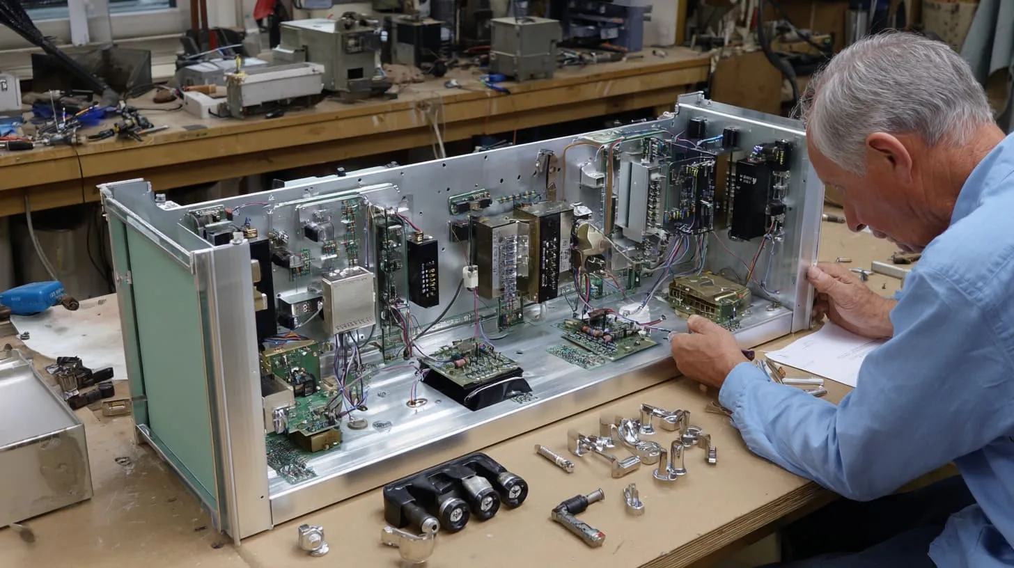
I do not think most grounding mistakes happen because people are careless. I think they happen because the problem looks smaller than it is.
A designer focuses on the PCB. A buyer focuses on cost and lead time. A factory focuses on manufacturability. A test lab focuses on results. The project moves fast, and the tiny grounding detail slips through the gap.
Relying on coating for electrical contact
This is one of the biggest mistakes.
Paint, anodizing, and powder coating are not your friends when you need electrical continuity. They help the surface look good and last longer, but they often block the contact path.
Still, many drawings quietly assume that two coated parts connected by screws will bond well enough.
That assumption causes trouble.
| Mistake | Real result |
|---|---|
| Using anodized surface as contact area | Weak or no continuity |
| Counting on painted panel edge | Unstable bond |
| No bare metal zone defined | Random electrical behavior |
Ignoring grounding early in design
When grounding is left too late, the fixes get ugly.
Late fixes often mean:
- extra machining
- manual rework
- hardware changes
- sample delays
- higher cost
I have seen projects where one missing grounding note on the first drawing later created three rounds of back-and-forth between engineering, production, and the customer.
That is expensive in a quiet way.
Overcomplicating grounding schemes
Some designers make the opposite mistake. They treat grounding like a magic cure and add too many connections everywhere.
More ground points are not always better.
Too many poorly planned paths can:
- create loops
- increase noise coupling
- confuse assembly
- make troubleshooting harder
The trap here is emotional. A complex grounding scheme can look more “serious.” But serious-looking is not the same as correct.
I become careful when I see a design with many grounding points but no clear reasoning for each one, because that often means the system is growing by fear instead of by function.
Poor communication with manufacturers
This one hurts custom OEM work a lot.
A customer may understand what they want in their head, but if the drawing does not show:
- grounding locations
- masked areas
- hardware type
- continuity expectation
- bonding path across parts
then the factory may guess.
Guessing is dangerous.
| Missing information in drawing | What can happen |
|---|---|
| No grounding point marked | Factory chooses convenient point |
| No surface removal note | Coating blocks contact |
| No hardware detail | Wrong washer or fastener used |
| No continuity requirement | QC does not check it |
A short mistake summary
- Do not assume mechanical contact equals electrical contact
- Do not leave grounding decisions for the end
- Do not add many grounding points without logic
- Do not expect the supplier to infer critical EMC details from a general drawing
Once these common mistakes are clear, the next step becomes more useful: building a better process from the start.
Best Practices for OEM and Custom Enclosure Projects
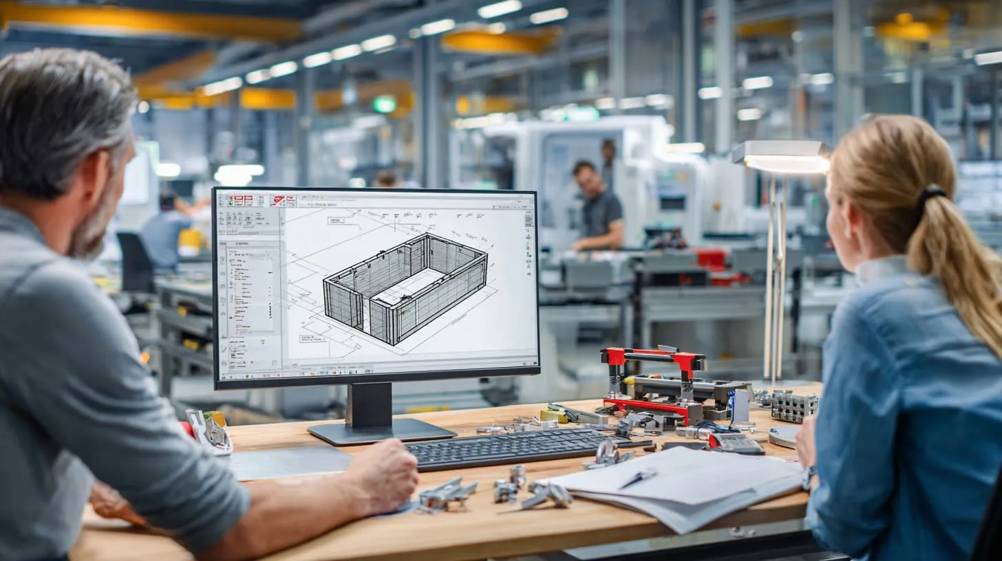
I like practical rules more than pretty theory. In custom enclosure work, practical rules save time.
Good grounding and bonding results usually come from clear planning, not late heroics.
Design-stage checklist
I think grounding should be discussed as early as:
- enclosure structure
- board mounting
- connector layout
- surface finish planning
At the design stage, I want clear answers to these questions:
- What kind of grounding does the product need?
- Which parts must be bonded?
- Where are the critical contact points?
- Which surfaces will be coated or anodized?
- Which seams matter for shielding?
- Which removable parts need repeatable continuity?
| Design question | Why I ask it early |
|---|---|
| Is protective earth required? | Affects safety path and hardware |
| Does the enclosure support EMC shielding? | Affects seam and contact design |
| Where does PCB ground meet chassis? | Affects noise and compliance |
| Will the enclosure be anodized? | Affects contact planning |
The projects that move most smoothly are usually the ones where these questions get answered before the first polished sample, not after the first failed test.
Drawing and documentation tips
A drawing should not only describe shape. It should describe intent.
Useful notes include:
- mark grounding points clearly
- mark masked or bare metal contact areas
- specify hardware if it matters electrically
- note continuity requirement where needed
- define conductive gasket or strap location
Here is the kind of drawing detail I like to see:
| Drawing item | Good note example |
|---|---|
| Ground stud location | “M4 grounding stud, bare contact area required” |
| Contact zone | “Mask before anodizing” |
| Panel seam | “Conductive gasket along full seam” |
| QC need | “Continuity test required after assembly” |
That level of detail reduces confusion between customer, engineer, and factory.
Collaboration with suppliers
This part matters more than many buyers admit.
A supplier may know machining very well but still miss EMC intent if nobody explains it. A buyer may understand the product goal but still forget to define the manufacturing detail.
That is why I value DFM discussion.
A good supplier should ask:
- Which points must stay conductive?
- Can coating be removed at selected areas?
- Does the removable panel need a bonding strap?
- Is continuity testing required in production?
I trust a factory more when it pushes back on an unclear grounding design instead of simply quoting it and hoping nothing goes wrong.
Testing and validation
Testing should not wait for the final compliance lab stage.
I prefer small checks earlier:
- continuity measurement
- seam contact review
- pre-compliance EMC scan
- assembly repeatability review
| Validation step | Purpose |
|---|---|
| Continuity test | Confirms metal path is real |
| Visual check on contact points | Confirms coating removal or masking |
| Assembly repeat test | Checks reliability after repeated opening |
| Pre-compliance EMC scan | Finds risk before final certification |
A project becomes easier to trust when the grounding path is not only designed, but also checked.
And once the design process is more solid, the next big question naturally appears: what standards should guide all of this?
Standards and Compliance You Should Know
I know standards can make people tired. The names feel dry. The documents feel long. But ignoring them does not make them disappear.
Grounding and bonding are deeply tied to compliance. A designer does not need to memorize every clause, but they do need to know what kind of rule is shaping the product.
Key international standards
For safety, designers often run into standards connected to IEC or UL frameworks. The exact standard depends on the product type, voltage, environment, and market.
These standards often define expectations for:
- protective grounding
- fault protection
- accessible metal parts
- creepage and clearance relationships
- construction requirements
| Standards area | Why it matters |
|---|---|
| IEC safety rules | Common reference for international product design |
| UL safety rules | Important for North American market access |
| Product-specific standards | Requirements change by device type |
I do not try to sound clever here. I simply ask early which market the product must enter, because the answer changes which compliance path matters most.
EMC standards overview
EMC standards look at whether the device creates too much interference or is too sensitive to interference.
Grounding and bonding affect:
- enclosure shielding quality
- cable behavior
- seam leakage
- common-mode noise paths
Design teams often hear names like:
- CISPR
- FCC
- IEC EMC standards
The exact standard changes by market and product category, but the design lesson stays similar: poor grounding and poor bonding can ruin EMC performance even when the core electronics are decent.
Industry-specific requirements
Not all products face the same level of control.
Industrial equipment, consumer electronics, telecom gear, and medical products can have very different expectations.
| Product type | Typical grounding concern |
|---|---|
| Industrial equipment | Safety and noise in harsh environments |
| Consumer electronics | Compact layout and compliance cost control |
| Telecom devices | Shielding and signal integrity |
| Medical devices | Strict safety and functional reliability |
This matters because designers sometimes borrow grounding ideas from the wrong industry. A method that feels acceptable in one device may be weak or non-compliant in another.
A practical compliance mindset
I tell customers this often: standards do not replace engineering judgment, but they do punish vague thinking.
That is why I like to know three things early:
- Which markets will the product enter?
- Which safety path applies?
- Which EMC target matters most?
Those answers help the mechanical design make more sense.
And once standards enter the picture, the business side becomes impossible to ignore, because every design choice here affects cost and time too.
How Grounding and Bonding Affect Cost and Lead Time

This is the part many buyers feel most directly.
A weak grounding design does not only create technical risk. It can also change quotation cost, sample speed, production flow, and shipping schedule.
Design decisions that increase cost
Some grounding and bonding choices add cost in a very direct way.
Examples include:
- extra machining for studs or contact zones
- masking areas before anodizing
- adding conductive gaskets
- adding copper straps
- manual continuity checks
- added assembly steps
| Cost driver | Why it increases cost |
|---|---|
| Masked contact zones | Extra surface treatment handling |
| Ground studs or inserts | Added hardware and labor |
| Conductive gasket | Extra material cost |
| Bonding straps | More components and assembly time |
| Retesting after failure | Lab and engineering cost |
These are not always bad costs. Some are smart costs. The real question is whether they are planned or forced by late problems.
Cost-saving strategies
I like cost reduction that comes from clear design, not from cutting essential details.
The best cost-saving moves are often:
- define grounding early
- integrate bonding into existing structure
- avoid unnecessary extra parts
- reduce sample revision loops
- use one clear grounding strategy instead of three uncertain ones
| Better choice | Why it saves money |
|---|---|
| Planned bare contact area | Avoids random rework |
| Integrated bonding point | Reduces added hardware |
| Early EMC thinking | Reduces retest risk |
| Clear drawing notes | Cuts communication waste |
I judge “cheap” and “low-cost” very differently in enclosure work. Cheap means the quotation looks good at first and gets painful later. Low-cost means the design avoids waste without creating hidden risk.
Lead time considerations
Lead time suffers when grounding details are unclear.
A project can slow down because:
- the factory asks for clarification
- the sample must be remade
- surface treatment must be changed
- compliance testing must be repeated
- assembly instructions must be revised
I have seen one tiny missing note about masking a grounding point delay a project far more than one extra machining step would have done in the beginning.
That is why I often prefer a slightly more careful first sample over a fast sample that teaches the same lesson the hard way.
A quick business view
| Situation | Short-term feeling | Long-term result |
|---|---|---|
| Skip grounding detail to save time | Faster first quote | Higher risk later |
| Plan bonding at drawing stage | More discussion early | Faster execution later |
| Ignore continuity test | Less QC cost now | More field or lab risk |
| Add smart grounding detail | Slightly higher sample cost | Lower project friction |
The business lesson is simple. Grounding and bonding do affect cost. But uncertainty affects cost even more.
That brings me to the final practical section: how I think a supplier like MaidaTech can help customers deal with this without turning every project into a long engineering argument.
How MaidaTech Supports Your Grounding and Bonding Needs
I do not believe customers need a supplier who only says yes. I think they need a supplier who notices risk early and speaks clearly about it.
That matters a lot in grounding and bonding work.
Engineering support for OEM projects
When I review an OEM enclosure project, I do not only look at dimensions and holes. I also look for hidden grounding trouble.
I usually review:
- panel contact logic
- possible anodizing conflict
- grounding point placement
- removable part continuity
- hardware suitability for electrical contact
That is especially useful for customers like Davide or John, because they often know what the product must do, but they still need fast manufacturing feedback that turns the idea into a reliable enclosure.
Custom enclosure solutions
MaidaTech can support custom enclosure needs by helping define:
- grounding stud positions
- bonding hardware options
- masked areas for conductivity
- surface finish choices that fit both appearance and function
- enclosure revisions when the original concept creates risk
| Support area | How it helps the customer |
|---|---|
| Grounding point review | Reduces unclear electrical paths |
| Surface finish advice | Avoids coating-related bonding issues |
| Redesign input | Improves manufacturability and compliance readiness |
| Custom hardware options | Supports stable assembly and continuity |
I pay most attention when the product needs both a clean appearance and reliable electrical performance, because that is where a lot of bad compromises get made if nobody slows down and thinks.
Quality control and testing support
A grounding idea is only useful if production can repeat it.
That is why QC matters.
Support can include:
- checking masked or bare contact zones
- confirming correct hardware use
- continuity testing after assembly
- reviewing consistency across production batches
| QC check | Why it matters |
|---|---|
| Bare metal area confirmed | Ensures contact point exists |
| Hardware match confirmed | Prevents assembly variation |
| Continuity test performed | Verifies bonding path |
| Batch consistency checked | Protects repeatability |
From my side, the goal is not to make the project sound more complex than it is. The goal is to remove the kind of hidden weakness that causes trouble later.
And after all of this, the last thing I want to leave with the reader is not fear. It is clarity.
Conclusion
Grounding and bonding do not usually get the spotlight in device design. Still, they shape the outcome more than many people expect.
A product can have a smart board, a nice enclosure, and a clean brand look, yet still suffer because the grounding path is vague or the bonding between metal parts is weak. I have seen that gap cause EMC failures, redesign cost, sample delays, and frustrating arguments that should never have happened in the first place.
What this topic has taught me is simple. Good grounding is not about adding random connections everywhere. Good bonding is not about hoping the screws will handle it. The real work is in knowing what kind of grounding the product needs, how the enclosure parts should behave electrically, and where surface finish or assembly detail may quietly break that plan.
I think the best results come from early thinking, clear drawings, realistic testing, and honest supplier communication.
A simple grounding strategy that is clearly defined will usually beat a messy design that tries to solve the problem late. That is true for safety. It is true for EMC. It is true for cost control too.
When grounding and bonding are done well, nobody praises them much. The product just works. The test result feels calmer. The launch feels smoother. The enclosure behaves like it should.
That is enough for me.
If you are working on a custom aluminum enclosure or device housing and want a second look at grounding points, bonding details, or enclosure structure, you can reach out to me at info@maidatech.com or visit maidatechenclosure.com. I am always happy to review a design and help spot the kind of small details that can save a project from bigger trouble later.