Skip to content

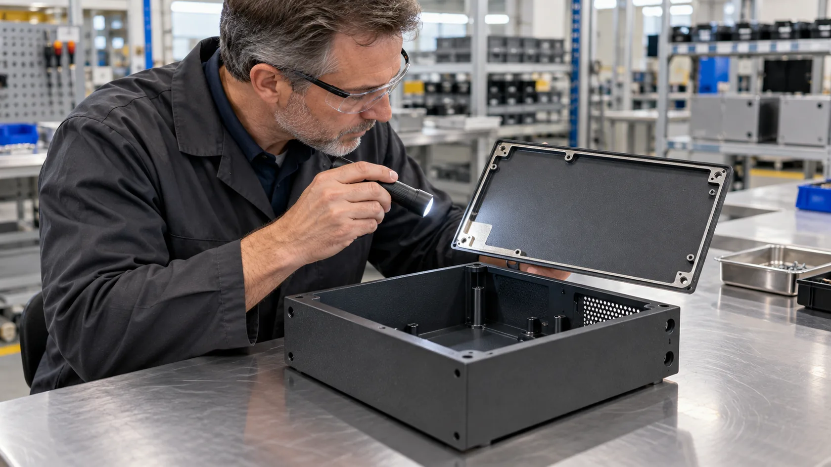
A first article can look exactly right and still be electrically wrong. The powder coat is even, the corners are protected, and the lid sits squarely. Then someone tries to verify the earth stud or the lid seam and finds a finish layer between every intended contact surface.
Powder coating is often a sensible choice for a metal enclosure. It can provide a durable cosmetic and corrosion-protection finish. The trouble starts when a finish instruction silently covers an EMC or bonding interface. The enclosure is still metal, but the assembled path may no longer be electrically continuous where the design expected it to be.
In my experience, this is rarely a powder-coating failure. It is a handoff failure between electrical intent, mechanical drawing, fabrication, and finishing. The useful correction is not “leave everything bare”; it is to identify every interface that needs conductivity, then make the finish plan protect that requirement.
That distinction becomes clear once we treat the coating as part of the joint stack-up rather than as decoration added at the end.
Why Powder Coating Changes an EMC Joint
The coating is part of the electrical stack-up
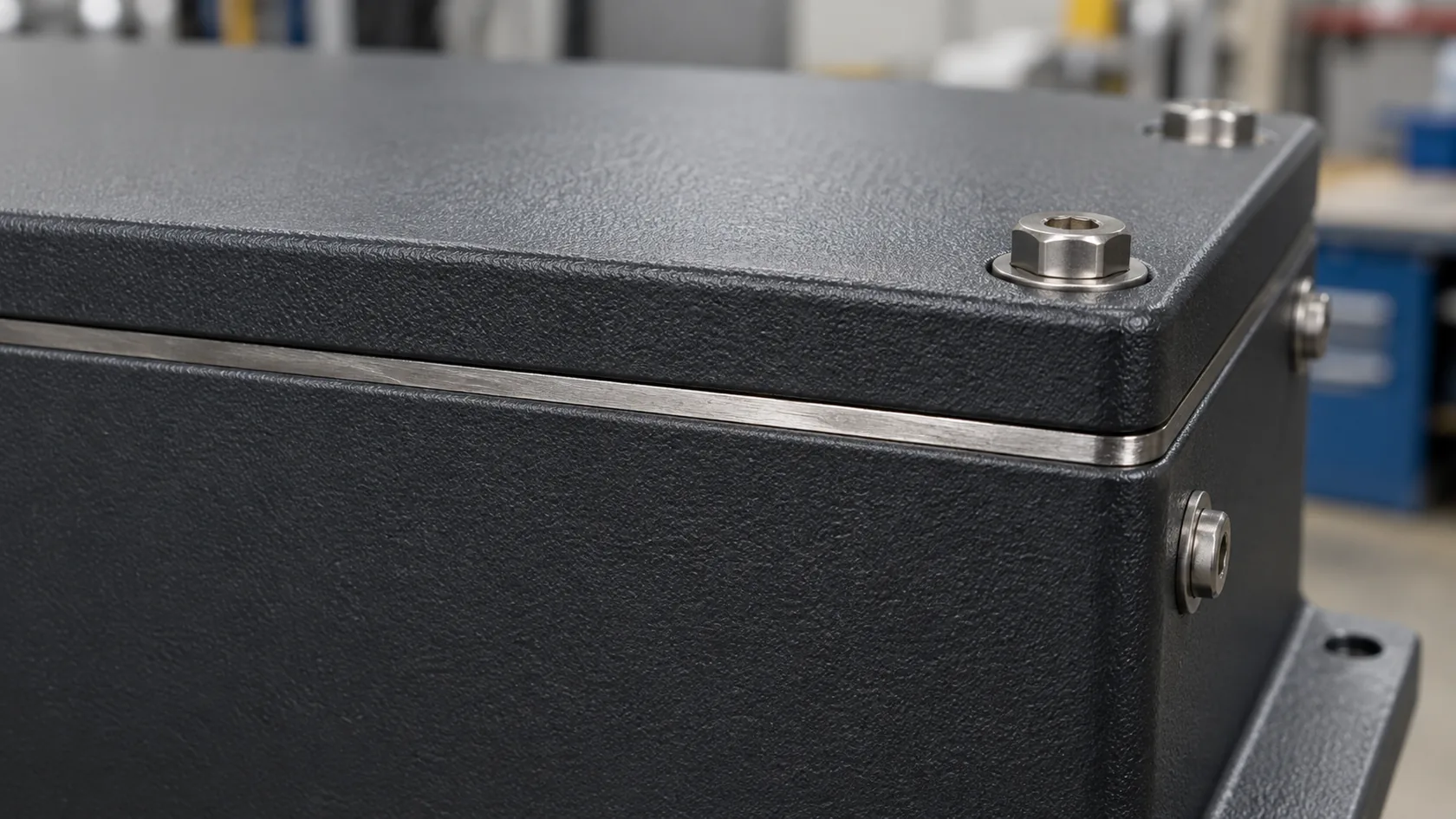
A coated enclosure shell is not automatically a bonded enclosure assembly. A cured powder coating is normally selected as a protective polymer layer, so an ordinary coating should not be assumed to conduct across a lid seam, mounting plate, connector flange, or earth connection. “Metal enclosure” describes the parts; it does not define the completed electrical interfaces.
The European Commission's EMC guidance puts EMC in an equipment-level context. That matters here: a neat powder-coated box or a single DC continuity reading cannot establish the performance of the finished apparatus.
I ask the design team to separate these jobs before we discuss masking:
| Interface | Possible function | Why coating needs a decision |
|---|---|---|
| Protective-earth stud or terminal | Protective path required by the product and installation design | Paint under the terminal, washer, or hardware can interrupt the intended contact |
| Lid-to-body seam | EMC shielding continuity | A long painted seam can leave the conductive shell divided into separate pieces |
| Connector shell or cable shield entry | Shield termination | A coated flange may interrupt the intended connector-to-housing interface |
| Internal chassis or mounting plate | Defined bond, return path, or static control | Mechanical fasteners may only touch finished surfaces |
Safety bonding, low-frequency continuity, static control, and RF seam behavior are related but not interchangeable. NASA's Electrical Bonding Design Guide likewise treats bonding as a design requirement that must be communicated clearly to manufacturing. I have seen a painted earth point pass a visual check simply because nobody wrote down what that location was meant to do.
Once the intended current path is named, the finish decision stops being a general preference and becomes an interface-by-interface engineering choice.
Define the Bond Before Choosing a Finish

Write the function at each interface
“Ground the enclosure” is not enough information for a fabrication drawing. It can mean a protective-earth connection, bonding of a removable door, a cable-shield termination, an ESD path, an EMC seam, or several of these. The required geometry, hardware, finish treatment, and verification method can differ substantially.
Before powder is selected, I recommend a short bond map like this one:
| Drawing location | Required function | Mating parts | Control to define | Evidence to request |
|---|---|---|---|---|
| Lid perimeter | EMC seam, if required by the product design | Lid, body, gasket or spring contacts | Contact track, fastener layout, flatness, compression, finish exclusion | Representative assembly and applicable EMC test evidence |
| Earth stud | Protective connection | Stud, washer, cable lug, chassis | Approved contact treatment, hardware stack, torque, corrosion protection | Required electrical and safety verification specified by the product owner |
| Connector opening | Cable-shield or chassis interface | Connector shell, flange, enclosure | Finish boundary, opening geometry, gasket or conductive hardware | Assembly inspection and applicable product test |
| Removable internal panel | Defined equipment bond | Panel, standoffs, chassis | Contact pads, hardware, assembly sequence | Project-specific continuity or bonding check |
Direct metal-to-metal contact can be useful where it suits the electrical and environmental requirement, but it is not a magic phrase. Sandia's electrical-bonding guidance calls for continuity across mechanical interfaces and notes that mating surfaces should be free of nonconductive contaminants such as paint, machining oils, and inks. That is a helpful design principle, not a substitute for the finished-product requirement.
My practical rule is simple: if a supplier cannot tell which two parts must connect and why, they cannot reliably choose whether to mask, treat, machine, or coat that area. Resolve it before a purchase order turns an ambiguous note into a production habit.
With the bond map agreed, the next task is to turn it into surfaces, boundaries, and assembly controls a finishing line can actually repeat.
Specify Contact Lands That a Factory Can Repeat
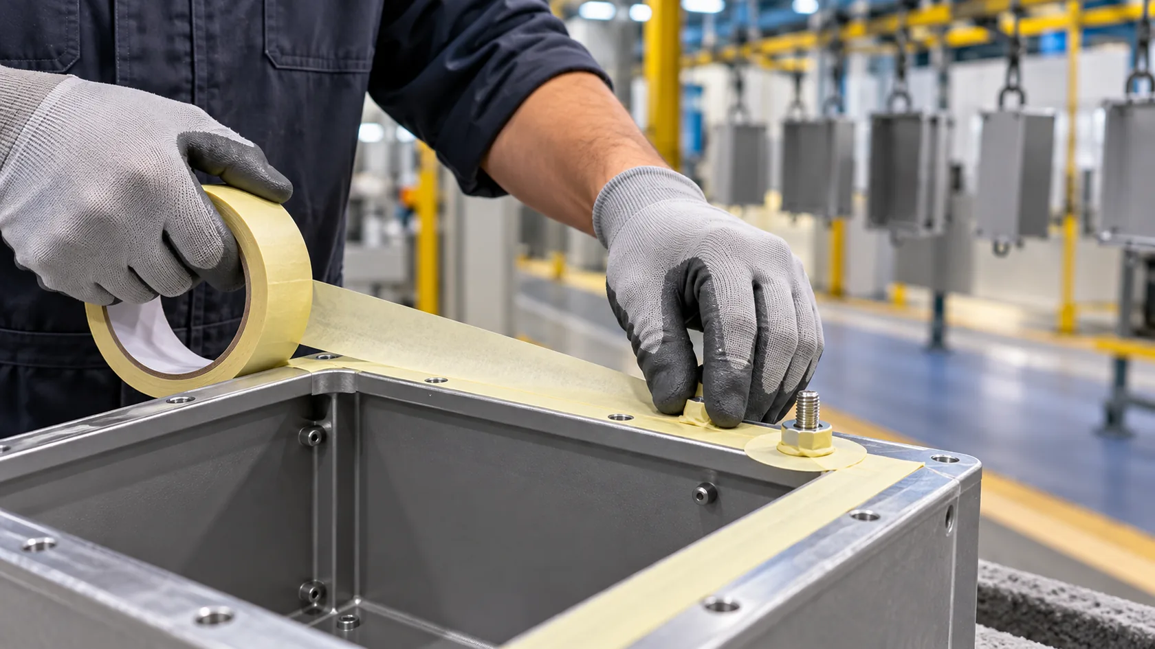
Turn the finish map into drawing controls
For a powder-coated EMC enclosure, the most repeatable strategy is often a controlled finish map: coat the exposed surfaces that need protection, and deliberately preserve or apply an approved conductive treatment at the interfaces that need it. The exact option depends on base material, corrosion environment, electrical function, assembly sequence, and cosmetic expectations.
| Approach | Where it can fit | Manufacturing question to settle | Main risk if it is vague |
|---|---|---|---|
| Planned masked contact land | Lid flanges, earth studs, connector interfaces | What is the exact boundary, tolerance, and protection during handling? | A shifting mask leaves too little contact area or an unacceptable visible strip |
| Approved conductive corrosion-control treatment | Aluminum or other material-specific contact locations | Is the treatment compatible with the material, exposure, and electrical requirement? | A bare land may corrode or a treatment may be substituted without review |
| Controlled post-finish machining | Accessible, well-defined interfaces where the process is validated | How are burrs, exposed edges, debris, and re-protection controlled? | A late scrape becomes an inconsistent manual repair |
| Qualified conductive coating or gasket system | A design explicitly engineered and validated for it | What property, thickness, mating hardware, and test basis are required? | Assuming a “conductive” product solves an unqualified seam |
Avoid leaving a contact land as “remove paint as needed.” That is difficult to quote and almost impossible to inspect consistently. Instead, identify the geometry, the finish boundary, the approved surface condition, the mating hardware, and how the area is protected after assembly. Where dissimilar metals, salt, moisture, cleaning agents, or condensation are present, add the corrosion review rather than treating conductivity and durability as separate departments.
Fasteners also deserve their own control. A serrated washer or other specified hardware may help establish contact in the right joint, but it does not replace flange stiffness, surface preparation, torque control, and corrosion management. On long EMC seams, a single bonded screw does not prove continuity around the perimeter. If a conductive gasket or spring contact is selected, its compression, spacing, mating surface, and service life need to be designed as one assembly.
I prefer masking designed into the part over a technician scraping powder after the fact. It costs a little attention early, but it avoids uncertain edges, touch-up discussions, and a contact path that changes from one operator to the next.
The only fair way to judge that specification is on the enclosure as it will actually leave the factory.
Validate the Finished Assembly, Not a Bare Box
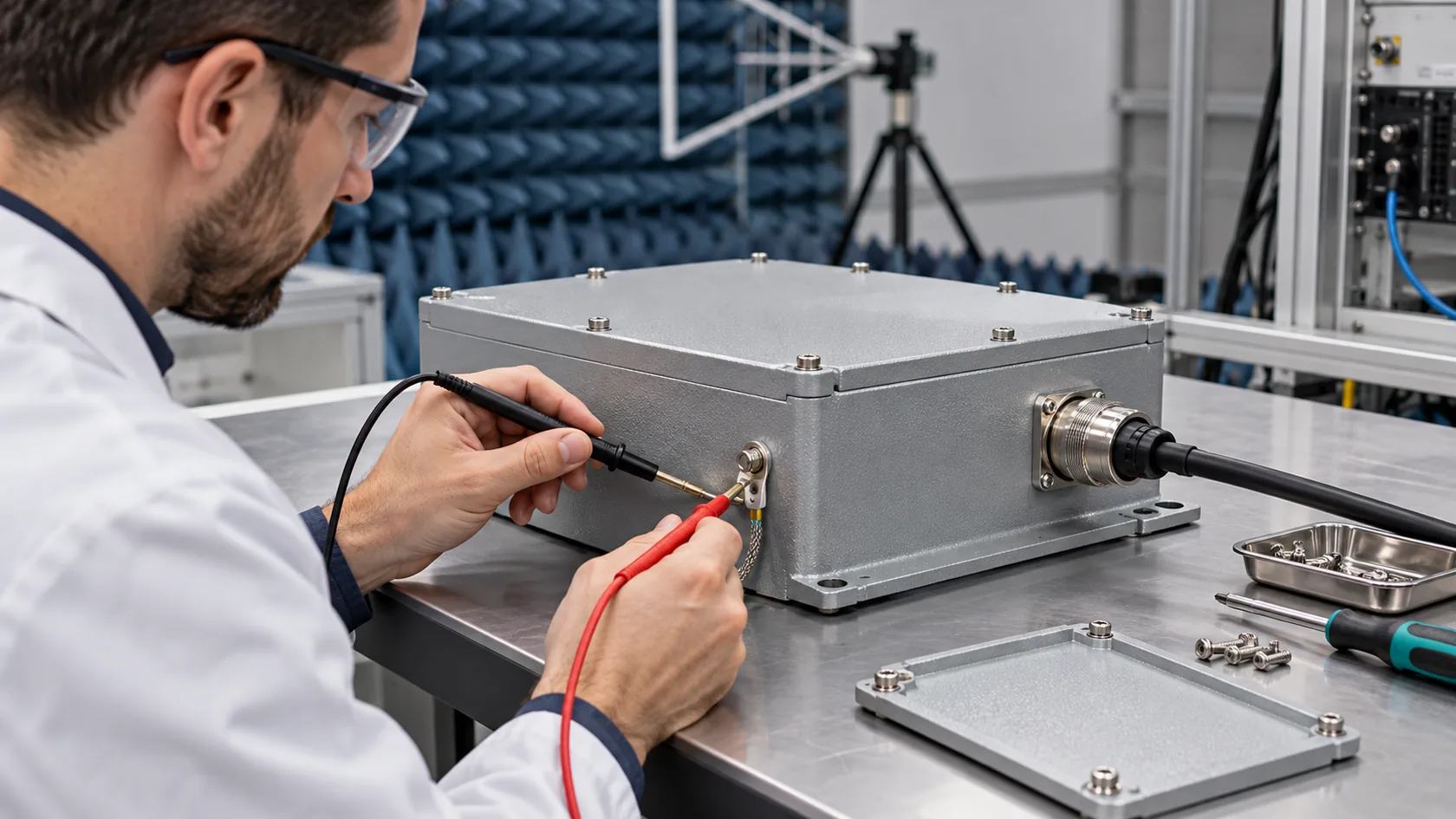
Test the representative configuration
First-article review should include more than the color chip and overall dimensions. Assemble the representative lid, gasket or contacts, fasteners, connector shells, cable shields, internal chassis, and any earth hardware. Inspect the contact lands for position, coverage, damage, contamination, and corrosion-protection condition. Confirm that the intended hardware reaches the intended surface after the actual assembly sequence.
For any required continuity or bond check, define the method before testing: the two probe locations, assembled condition, instrument, current or measurement approach where relevant, and project-specific acceptance criteria. The applicable system and product requirements determine the value and evidence; a generic factory number is not an EMC qualification.
This is especially important because DC continuity and RF shielding are not the same measurement. SAE ARP6248 describes a repeatable method to characterize the RF shielding behavior of conductive gasket materials and gaskets against joint surfaces. It is a useful reminder that seam behavior depends on the gasket, surfaces, and test setup—not only on whether a meter beeps across one fastener.
Use three levels of evidence:
- **Process evidence:** finish-map revision, masking instructions, approved materials, and first-article photos.
- **Assembly evidence:** inspection of the actual contact interfaces, specified hardware, torque or compression controls where applicable, and defined electrical checks.
- **Product evidence:** the responsible product team’s representative EMC, safety, environmental, and service validation for the intended market and configuration.
The active MIL-HDBK-1857 overview covers grounding, bonding, and shielding practices for electronic equipment and systems. Its scope is broader than a custom enclosure quotation, but it reinforces the point that these are system design practices, not cosmetic finish decisions.
From the factory side, I also check a later production piece, not just the first success. Masking, racking, pretreatment, hardware lots, and assembly instructions can all drift. A controlled recheck is cheaper than discovering the change when the finished equipment returns from EMC testing.
That production discipline lets powder coating remain a useful finish without asking it to do a job it was never specified to perform.
Conclusion
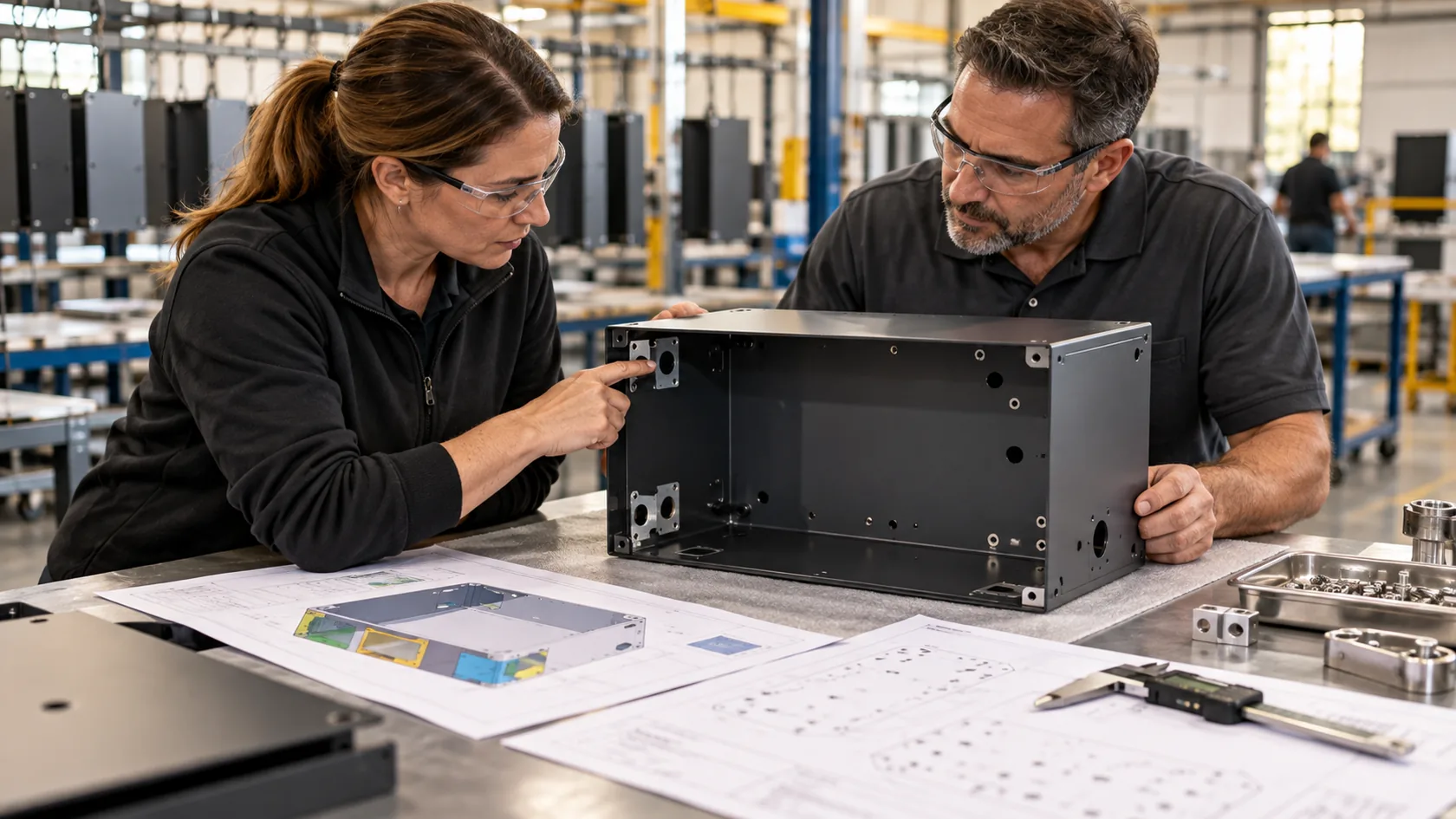
Powder coating turns into an EMC bonding problem only when it is allowed to cover a path that the completed product needs to keep conductive. The finish itself may be the right choice for appearance and corrosion protection. The real requirement is to define the contact interfaces early, preserve them deliberately, protect them for the actual environment, and verify the completed assembly.
After years of working through enclosure details with buyers, I have found that a one-page bond-and-finish map prevents more trouble than a late request to “improve grounding.” Before releasing a drawing, mark the lid seam, earth interfaces, connector shells, and removable parts; then review the mask boundaries, hardware, service exposure, and test basis with the enclosure and finishing teams. That is the practical point where a good-looking coating and a reliable EMC enclosure can coexist.