Skip to content

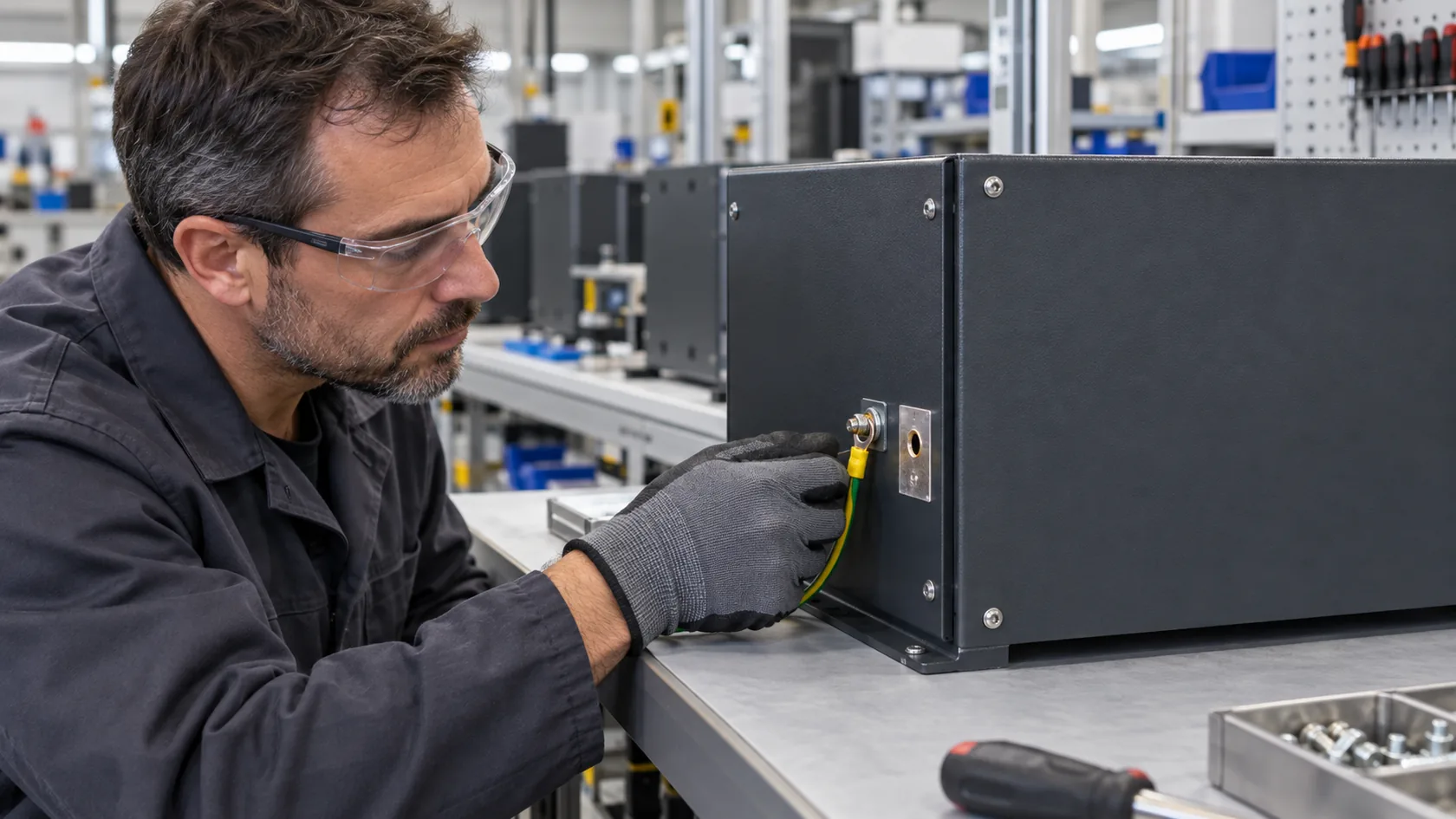
The most awkward grounding problems arrive after a sample looks finished. The powder coat is even, the enclosure is assembled, and the green-yellow wire has a terminal to land on. Then a first-article check finds paint between the lug, washer, and the metal that was supposed to form the protective path.
Powder coating is often a sound choice for a custom metal enclosure. It can help with appearance and corrosion protection. But it is normally an insulating finish, so it must not be treated as invisible at an electrical interface. A metal box with a ground symbol is not automatically a grounded assembly once the required contact surfaces have been coated.
For this article, I mean the practical enclosure work needed to support a required protective-earth or equipment-grounding connection. The product owner and qualified electrical designer must define the applicable safety, installation, conductor, fault-current, and verification requirements. My job as an enclosure supplier is to make the physical interface clear enough for fabrication, finishing, and assembly to repeat it.
The useful approach is not to leave broad bare areas or ask an operator to “scrape paint if needed.” It is to design a controlled electrical path and then protect every other surface as intended.
Start With the Required Grounding Function
Name the connection before selecting hardware
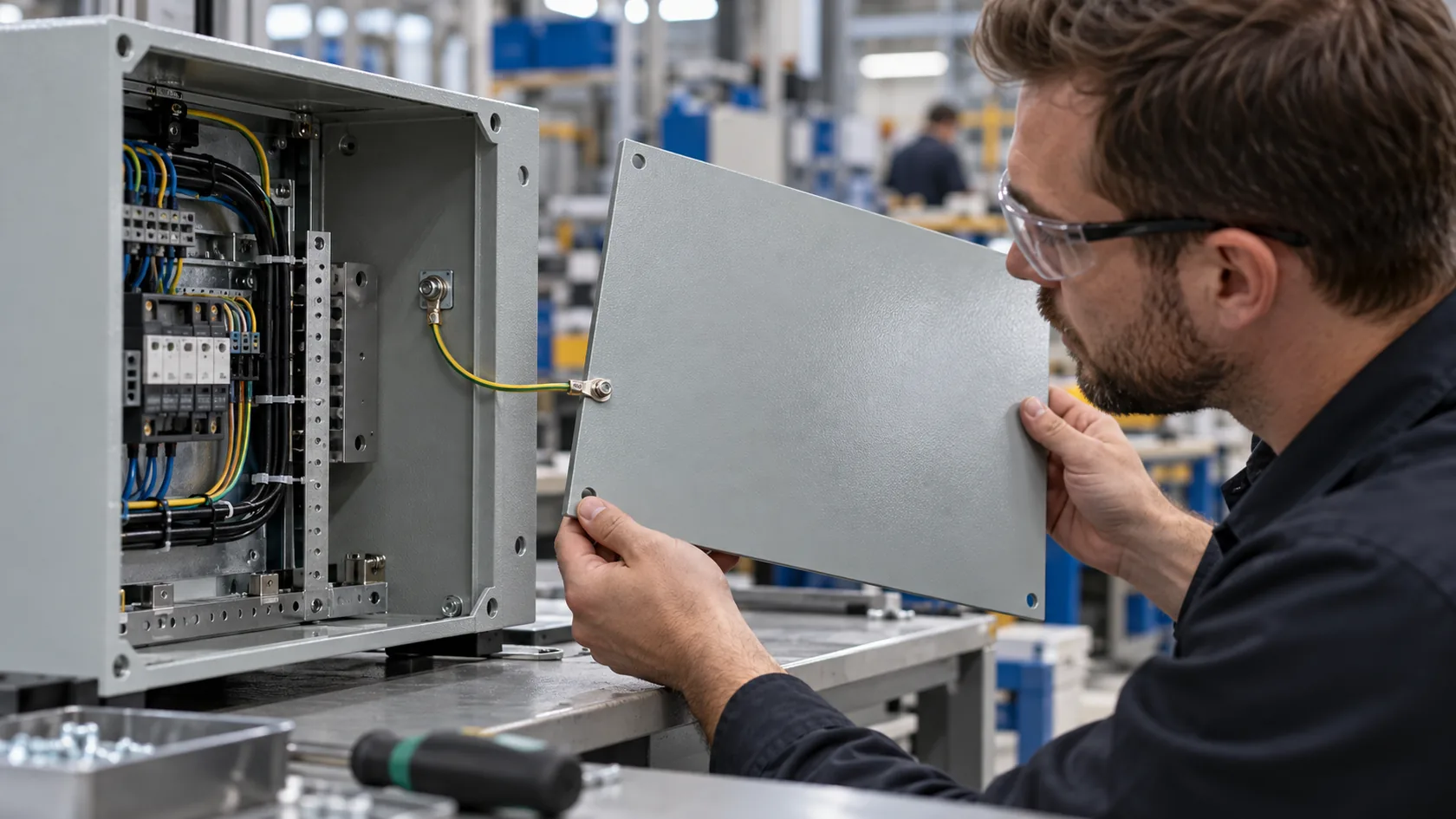
“Ground the enclosure” is too vague for a drawing. Depending on the equipment, it can mean a protective-earth connection to an exposed conductive chassis, bonding between separate metal parts, a cable-shield termination, a static-control path, or an EMC interface. These functions may meet at the same enclosure, but they should not be presumed to have the same hardware or evidence.
OSHA describes an equipment-grounding path as permanent and continuous, and explains that it must support fault-current protection rather than simply make a piece of metal feel connected. Its electrical-safety overview is a sensible reminder that a design needs a defined return path, not merely a convenient screw.
| Connection at the enclosure | Typical purpose | What needs definition |
|---|---|---|
| Dedicated PE terminal | Protective path for the specified equipment and installation | Chassis location, lug/hardware stack, finish boundary, access, marking, and applicable verification |
| Door or removable cover bond | Keep a separate conductive part at the required electrical relationship | Flexing, opening cycles, conductor routing, attachment points, and corrosion exposure |
| Internal panel bond | Maintain a specified chassis relationship | Surface condition, fastener stack, assembly sequence, and service access |
| Shielded connector or EMC seam | High-frequency or shielding behaviour | Geometry, seam/contact design, cable-shield termination, and representative EMC validation |
In my experience, this short separation avoids a costly shortcut: using the same painted fastener joint for safety grounding, a moving door, and RF shielding without confirming whether it can serve all three. A protective bond is a safety path; it is not an automatic EMC test result.
Once the function is named, the main chassis connection becomes much easier to design and quote correctly.
Create One Deliberate Protective-Earth Point
Put it on the part that carries the structure
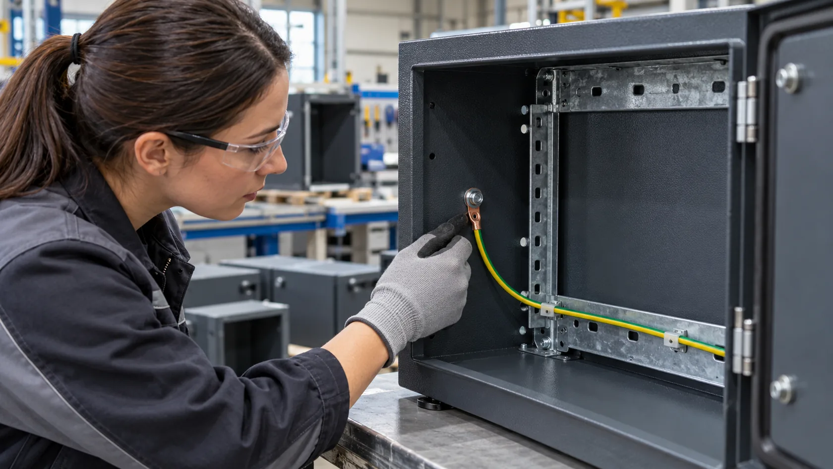
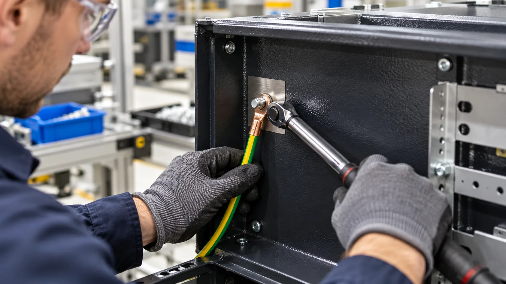
Where the equipment design calls for a protective-earth connection, I prefer a dedicated location on the primary structural chassis rather than an incidental lid screw or a decorative panel. It needs enough clear space for the specified lug and tool, a stable mechanical attachment, and an assembly sequence that lets a technician inspect the completed joint.
The relevant grounding rules vary by product and market, but UL notes that bonding is needed where necessary to maintain electrical continuity and safely carry likely fault current. Its discussion of metallic enclosure bonding is a useful example of why a mechanical connection alone cannot be assumed sufficient.
For the enclosure drawing, I would define at least these items:
- The exact chassis panel or formed feature that carries the connection.
- The contact land boundary and permitted surface treatment beneath the designated hardware.
- The approved stud, nut, screw, washer, lug, locking method, and any product-required torque.
- Clearance for conductor bend radius, tool access, inspection, and a nearby protective-earth symbol if the product design requires one.
- The material pairing and environmental control needed so an exposed contact land does not become a corrosion problem.
I would not place a PE point under a PCB, behind a sealed cable bundle, or on a thin cosmetic cover simply because the CAD model has free space there. The best terminal is one that remains mechanically sound, accessible, and electrically intentional after the actual paint, wiring, and service sequence.
That main point establishes the chassis path; it does not by itself prove that every detachable metal part is included.
Bond Doors, Covers, and Separate Metal Parts
Do not count on a hinge or painted screw
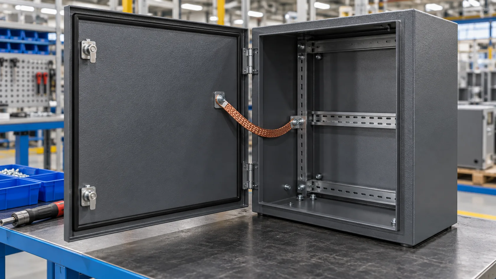
A removable lid, service door, or separate mounting panel may be metal and still be electrically isolated. Paint, oxide, hinge lubricant, vibration, loose hardware, and repeated opening can interrupt a path that looked fine on the first assembly. If the product design requires that part to be bonded, show the intended path directly.
A flexible bonding strap or jumper can suit a frequently opened or vibration-prone part when its length, bend path, fastening, protection from pinch points, and service movement are properly considered. A controlled direct joint can suit a rigid panel that will rarely be removed. The choice depends on the required function, current/frequency behaviour, expected cycles, exposure, and the approved equipment design.
Schneider Electric’s cabinet-cabling guidance makes the broader point: cabinets use deliberate interconnections among frames, panels, roofs, and doors; it also separates grounding hardware from unpainted EMC component interfaces. That distinction matters on powder-coated work.
My factory check is simple: if opening the cover, repainting a fastener, or changing the assembly order can silently break the path, it is not controlled enough yet. A hinge should not be assumed to be a reliable protective-earth route unless the approved product design specifically provides and validates it.
The next issue is the joint itself, because even a good strap or stud cannot work through an unintended insulating layer.
Keep Coating Out of the Intended Contact Stack
Specify a contact land, not an informal paint scrape
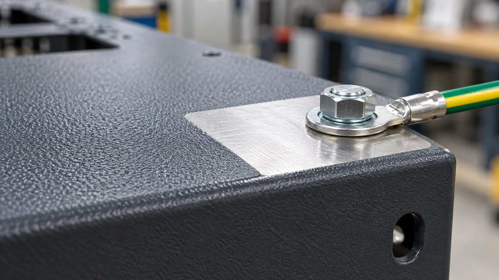
The cleanest manufacturing answer is usually a defined contact land: a bounded area where the finish is deliberately excluded or an approved conductive surface condition is specified for the connection. It should be large and located for the real hardware stack, but no broader than needed for the functional and corrosion requirements.
| Approach | When it may fit | Control needed |
|---|---|---|
| Masked contact land before coating | Accessible PE studs, pads, and defined chassis interfaces | Exact drawing boundary, masking method, handling protection, and visual inspection |
| Approved conductive treatment | Material- and environment-specific interfaces that need corrosion management | Qualified material/finish combination, compatibility, and required verification |
| Controlled post-finish machining | Accessible geometry where a validated process can remove finish cleanly | Burr/debris removal, boundary control, exposed-edge protection, and inspection |
| Hardware designed to establish contact | Only where the approved joint design allows it | Correct surface, hardware stack, torque, corrosion review, and repeatability check |
NASA’s bonding survey covers the relationship among resistance, impedance, straps, corrosion, and finishes. Its scope is far beyond an ordinary commercial enclosure, but the principle carries over: coatings and surface condition belong in the electrical-interface design, not in a late cosmetic note.
I prefer planned masking over hand scraping after coating. A scrape can leave burrs, inconsistent exposed area, loose debris, and a visible repair that differs from unit to unit. The small amount of drawing detail needed early is usually cheaper than trying to recreate a reliable contact on finished product.
The best contact-land concept can still fail if the finishing and assembly teams receive different instructions, so it needs to appear in the same controlled record.
Put the Requirement on the Drawing and Traveler
Give finishing and assembly teams the same instruction
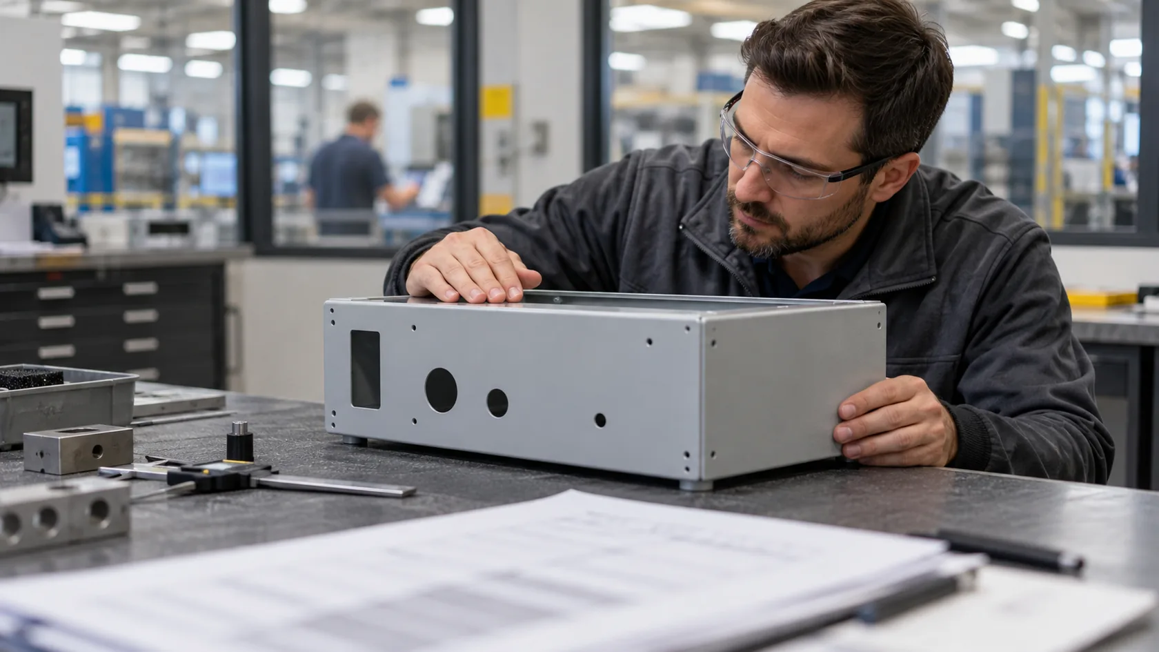
One general note such as “ground enclosure” creates room for interpretation. I ask for a compact interface table or drawing callouts that identify the connection point, the two mating parts, the function, the allowed surface condition, the specified hardware, the corrosion control, and the inspection evidence. The same information should follow the part through fabrication, coating, and assembly.
| Interface | Function | Finish instruction | Assembly control | Evidence |
|---|---|---|---|---|
| Chassis PE point | Product-defined protective-earth connection | Masked contact land or approved specified treatment | Named hardware stack and accessible installation | First-article photo and project-defined bond/continuity check |
| Removable cover bond | Product-defined bonding of separate conductive part | Prepared landing areas at both ends | Strap or approved direct-joint hardware; routing clear of pinch points | Assembly inspection and service-motion check |
| Internal panel | Defined chassis bond, if required | Contact pads located before finishing | Controlled fastener/sequence | Inspection against drawing |
| EMC cable or seam interface | Product-defined shield/seam behaviour | Separate EMC surface and geometry specification | Relevant gasket/contact/cable termination controls | Representative EMC evidence when applicable |
This is also where I identify ownership. The electrical designer supplies the equipment requirement and acceptance basis. The enclosure, finishing, and assembly teams supply repeatable construction and records. If a contract manufacturer changes the powder system, masking fixture, hardware lot, or panel design, that change needs review rather than being treated as a harmless production substitution.
The drawing does not need to become a standards textbook. It does need to tell a technician exactly what must touch, what must remain protected, and how the completed part will be checked.
Verify the Finished, Representative Assembly
Check the product that will actually ship
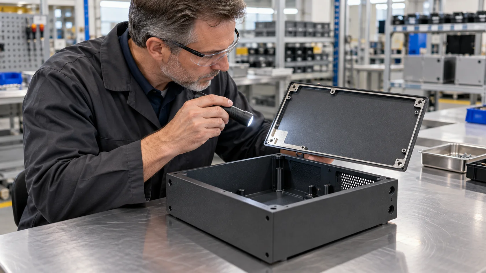
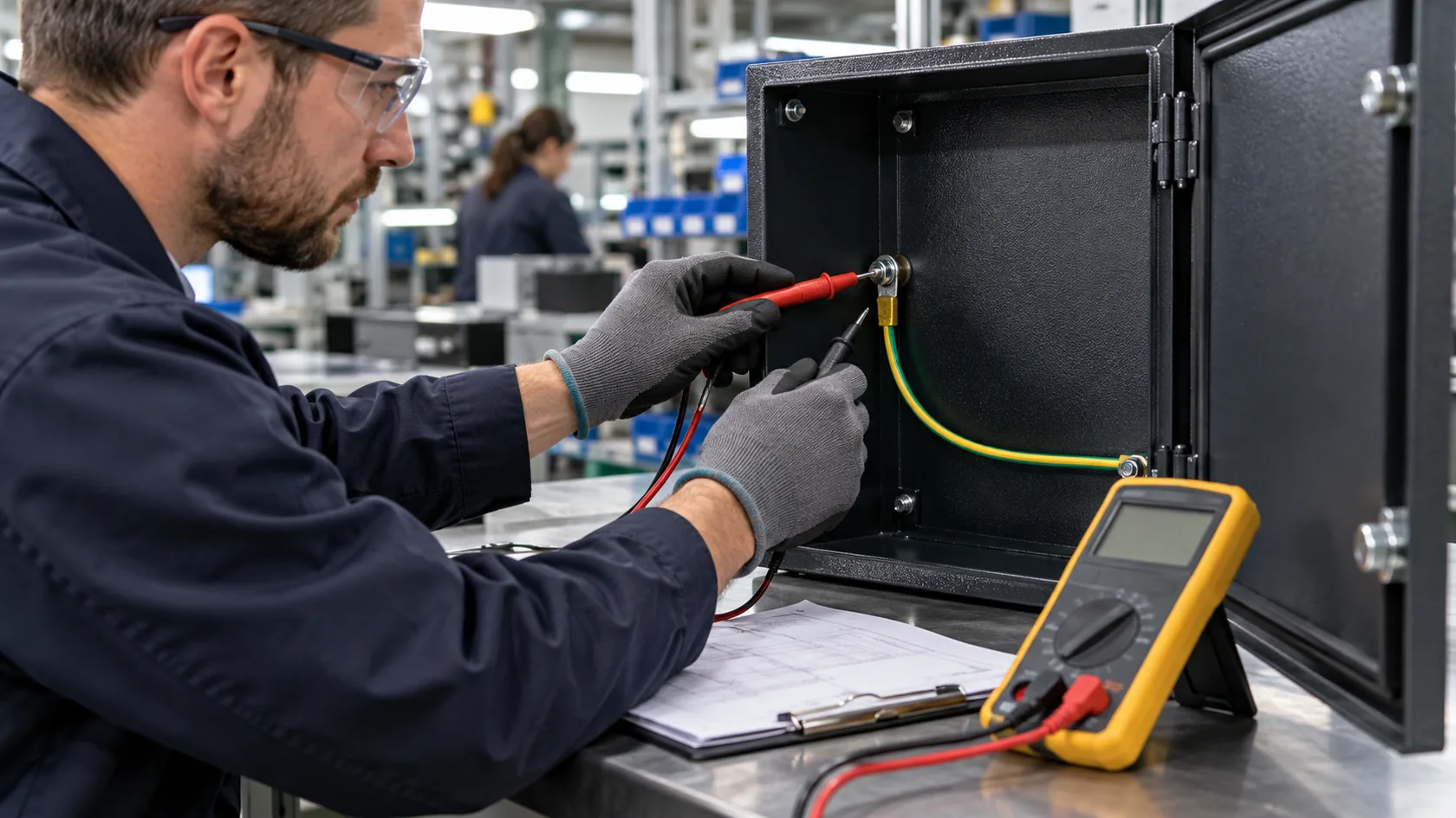
Inspect the same configuration that the customer will receive: coated chassis, specified terminal hardware, wiring lug, cover or door, cable entries, internal panel, and any gasket or shielded connector that affects the interface. Check that the contact land is in the right place, has not been contaminated or overcoated, and is still reached by the approved hardware after assembly.
For a required continuity or bonding check, agree the method before production: probe locations, assembly state, test equipment, current or measurement method where relevant, acceptance criteria, and sampling plan. The appropriate electrical and product requirements determine those details; a generic resistance number from a factory is not a universal compliance certificate.
Also keep EMC in its own lane. A low-resistance measurement at a PE stud says something about that selected DC path. It does not prove a cover seam, cable-shield termination, aperture, or finished apparatus has the shielding performance required at relevant frequencies. Where EMC performance is required, validate the representative finished configuration against the applicable product plan.
I recommend checking more than the first good sample. Masking placement, racking, finish thickness, handling, assembly hardware, and work instructions can drift in normal production. A short first-article record and periodic review cost far less than diagnosing a painted-over grounding point after equipment is wired.
That final check closes the loop: the intended path is no longer an assumption in a CAD model but a controlled feature of the delivered enclosure.
Conclusion
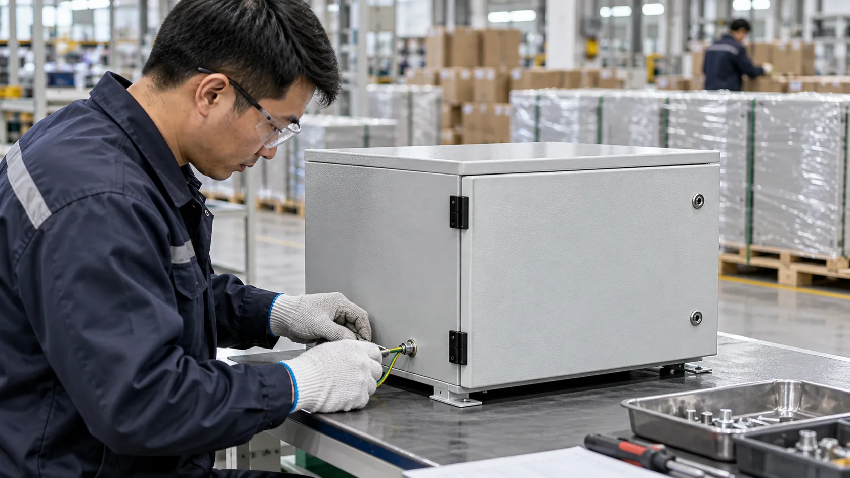
Grounding a powder-coated metal enclosure is mainly a matter of defining an intentional protective path before the coating line, not repairing paint after assembly. Name the required function, locate a dedicated chassis point, bond separate parts where the approved design requires it, preserve contact lands deliberately, and verify the representative finished assembly.
After years of working through enclosure details, I have found the best drawings make the electrical interface as visible as a cutout or bend. If you are planning a powder-coated enclosure, send the chassis layout, proposed PE point, removable-part details, environment, and cable-entry concept for a manufacturability review before finishing instructions are released.