Skip to content

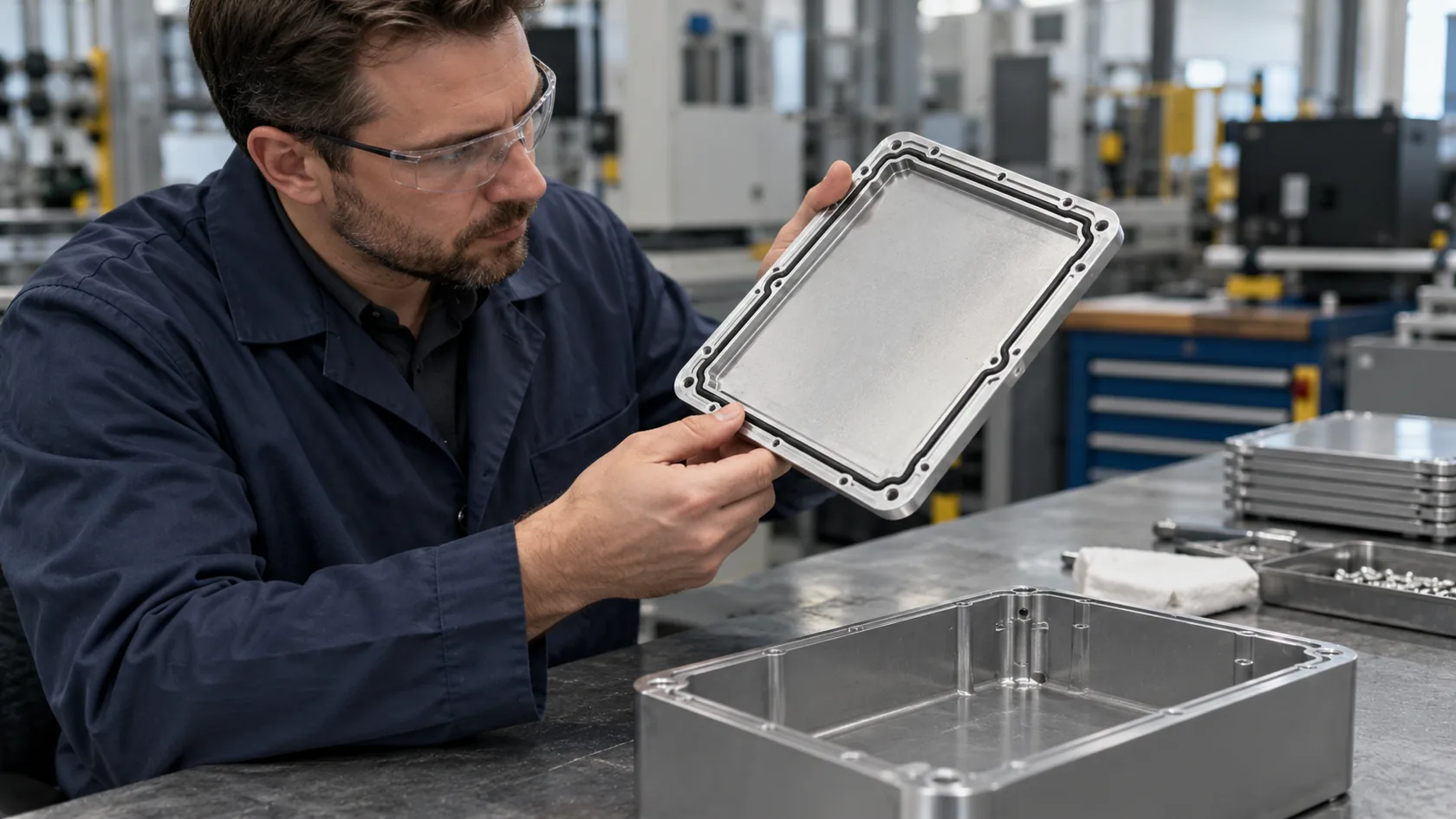
A conductive gasket can appear on an enclosure drawing long before anyone has established where the interference travels. It adds a part, an assembly step and another interface to control. Sometimes it is exactly the right part. Sometimes the failure is on a cable, at a vent, or inside the electronics, and a strip around the lid will do little to address it.
In my experience, the useful question is not whether a gasket is good or bad. It is whether this particular seam needs a compressible conductive bridge, and whether the complete product can maintain that bridge in production and service.
Start by separating the paths before selecting the part.
Diagnose the Path Before Buying a Gasket

Separate the seam from the rest of the system
Electromagnetic compatibility concerns the behavior of the finished equipment in its environment. The European Commission's EMC guidance sets out that broader equipment-level context. A metal enclosure or a continuity reading alone does not demonstrate compliance.
Ask the product engineer or test laboratory to identify the failing test, frequency range, operating mode and cable configuration. Near-field probing, controlled changes to individual interfaces, and repeat measurements can help locate a suspect path. Temporary conductive tape across a seam can be a useful diagnostic comparison if applied consistently; it is not proof that a production gasket will work or that the product complies.
| Observation to investigate | Possible next step |
|---|---|
| A repeatable change when the lid seam is bridged | Examine seam geometry, contact and the need for a gasket |
| A strong change when cable routing or termination changes | Investigate cable shielding, filtering and entry details |
| Sensitivity around a vent or display opening | Examine the aperture and the cooling or viewing requirement |
| Disturbance persists with the enclosure interface improved | Investigate the circuit, power path and other coupling routes |
These are clues, not automatic diagnoses. I would keep the original setup and change one variable at a time; otherwise a promising sample can hide a problem that returns with the production cable.
Once the seam is actually implicated, compare the mechanical options.
Consider a Better Mechanical Joint
Direct contact can be enough for a qualified design
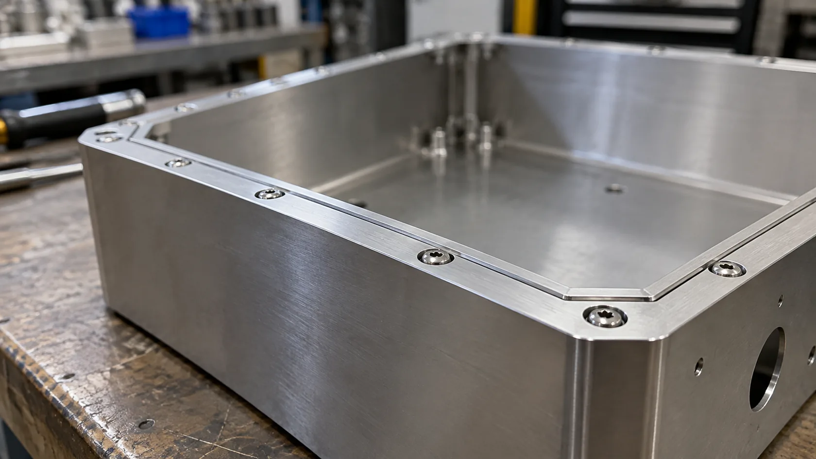
For a rigid, infrequently opened joint, a controlled metal-to-metal interface may meet the product's shielding needs without a separate conductive gasket. Options include a designed overlap with suitable fasteners, or a welded joint where access and fabrication permit. Neither is a universal replacement: gaps between fasteners, panel bow, surface condition and the frequency range still matter. A weld can remove service access or introduce distortion and finishing work.
| Joint option | Potential benefit | Question before ordering |
|---|---|---|
| Bolted or screwed overlap | Removable without a separate conductive gasket | Are contact lands, flatness and fastener spacing controlled and tested? |
| Welded seam | Permanent joint with fewer removable interfaces | Can the assembly tolerate distortion, access restrictions and finish repair? |
| Conductive gasket or spring contact | Bridges a designed removable interface | Can the assembly maintain the specified contact and compression? |
Anodizing, paint and other finishes can interrupt intended contact; even exposed aluminum develops an oxide. Specify the contact treatment, mating surfaces and inspection method with the finisher and equipment designer. A single screw-to-screw resistance measurement cannot establish shielding along an entire seam. I prefer to test a representative production joint before removing a gasket from the bill of materials.
If the enclosure seam is not the dominant route, move the effort to the actual boundary crossing.
Fix Cable, Vent and Circuit Problems at Their Source
Match the remedy to the path
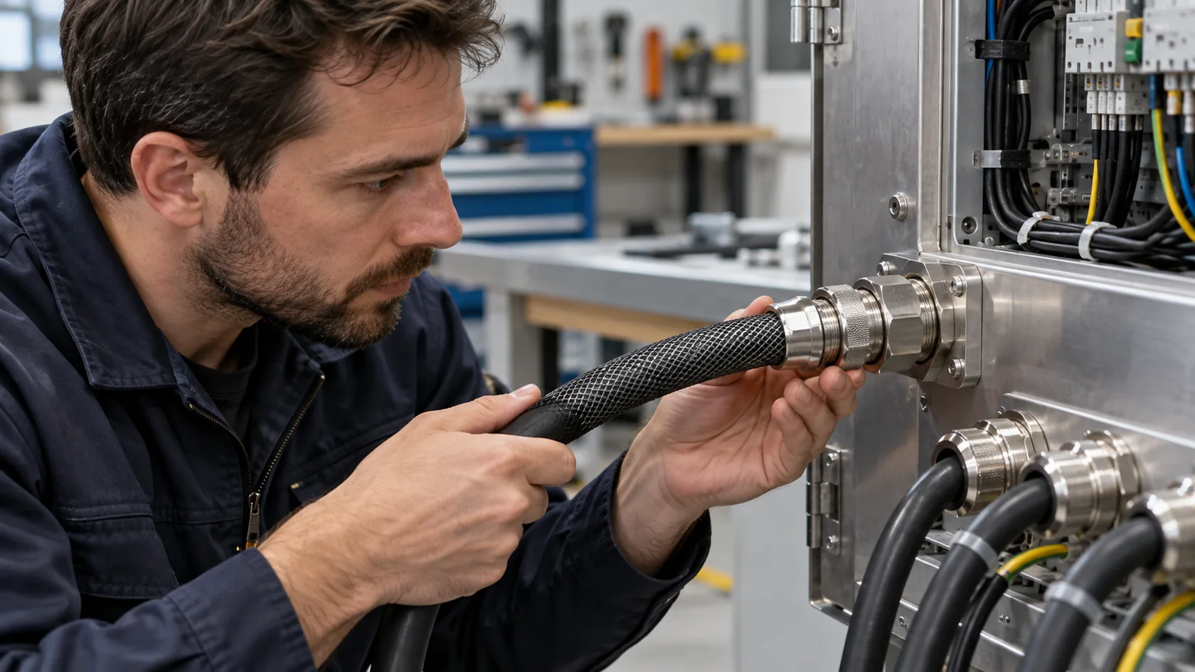
An enclosure may have excellent lid contact while a cable carries interference across its boundary. The equipment designer should assess connector construction, cable-shield termination, filters and their placement as part of the complete design. Schaffner's EMC filter application guidance discusses filter installation and the importance of the installation environment. Do not assume that fitting a shielded cable or filter automatically resolves every failure.
Openings for air, displays and controls also need their own treatment. A shielding vent or conductive window can be considered where justified, but each adds cost and must fit the airflow, optical, sealing and service requirements. Board-level shielding, layout changes or source suppression may be more effective when interference originates in a specific circuit. Each option needs evaluation with the actual hardware.
I ask for the cable type, connector and operating arrangement along with the enclosure drawing. A quote for a lid gasket without those details can be precise about the wrong component.
There is also a practical reason to challenge an unnecessary gasket: it creates its own constraints.
When the Gasket Creates New Problems

Compression, corrosion and maintenance
A conductive gasket needs appropriate mating surfaces and a controlled compression range. A thin cover may deflect between fasteners, while excessive compression can damage a gasket or overstress the joint. Compression stops, flange stiffness, fastener pattern, tolerances and assembly torque must be designed together; the selected material supplier should provide applicable limits. TE Connectivity's EMI shielding guidance discusses compression control and environmental sealing.
Moisture and dissimilar materials can also create corrosion at the interface. Parker Chomerics' conductive elastomer handbook addresses gasket and flange compatibility, protective finishes and seal design. Review the actual exposure and materials with the supplier; a separate environmental seal may be appropriate, but it must not prevent the conductive interface from working.
| Service concern | Buyer check |
|---|---|
| Repeated opening | Can technicians replace the gasket and restore the specified compression? |
| Water, salt or condensation | Are materials, drainage, protective finishes and seal layout compatible with the exposure? |
| Thin or flexible cover | Does the joint maintain contact across manufacturing tolerances? |
| Outdoor sealing and cooling | Have ingress, condensation and thermal behavior been evaluated together? |
I treat a combined environmental and EMC gasket as a system choice, not a shortcut to an IP rating. Cable entries, vents, fasteners and installation also affect ingress protection. Verify the intended installed configuration and maintenance procedure, including relevant environmental and EMC tests.
The final choice should follow evidence from that complete assembly.
Conclusion

I have found that a gasket earns its place when the seam needs a compliant conductive interface and the design can maintain it. Where testing points to a cable, opening or circuit, the better investment may be at that path. A simpler mechanical joint may also be suitable if representative testing supports it.
Before the next quotation, mark the suspected interference path, intended contact surfaces, service conditions and test configuration on the drawing. That gives the enclosure supplier and product engineer a practical basis for deciding whether a conductive gasket belongs in the design.