Skip to content
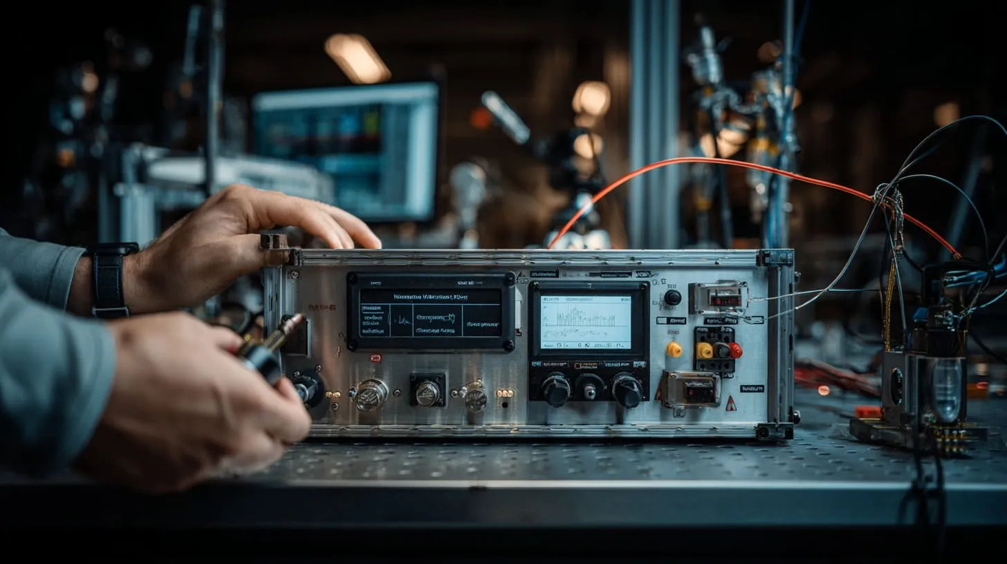
A metal enclosure can look excellent on the bench and still behave badly in an EMI test. I have seen that contrast more than once, and it always bothers me a little. The finish looks clean. The color looks premium. The customer feels pleased at first touch. Then the shielding result says something else.
That gap between appearance and function is exactly why I wanted to write about this topic.
A lot of people treat surface finish like the last layer of the job. They think about color, corrosion resistance, scratch resistance, and brand feel. I understand that. Those things matter. Buyers care about them. End users care about them. Engineers care about them too. But EMI does not care whether the finish looks expensive. EMI only cares whether current can move across the enclosure surface in a stable way.
That is where anodizing becomes tricky.
Aluminum itself is conductive. That part sounds simple. But the anodized layer on top of aluminum is a very different story. It protects. It hardens. It improves appearance. It also creates a barrier. And once that barrier sits in the wrong place, the shielding path can quietly fall apart.
I do not see this as a small technical footnote. I see it as one of those hidden decisions that can waste time, delay projects, and create avoidable redesign work. A team can choose the right material, machine the enclosure well, and still lose performance because the surface treatment was judged only by looks and durability.
The thing that pushes me to be careful is not theory. It is the pattern. A product gets assembled. The seams look tight. The screws feel secure. The coating looks flawless. Yet the conductive path is weak exactly where the enclosure needs it most.
One detail I weigh very early is whether the finish is helping the enclosure do its electrical job, or only helping it look finished to the eye.
That question changes the whole project.
And once I start thinking that way, the next issue becomes impossible to ignore: what role conductivity really plays in shielding in the first place.
What Role Does Electrical Conductivity Play in EMI Shielding?
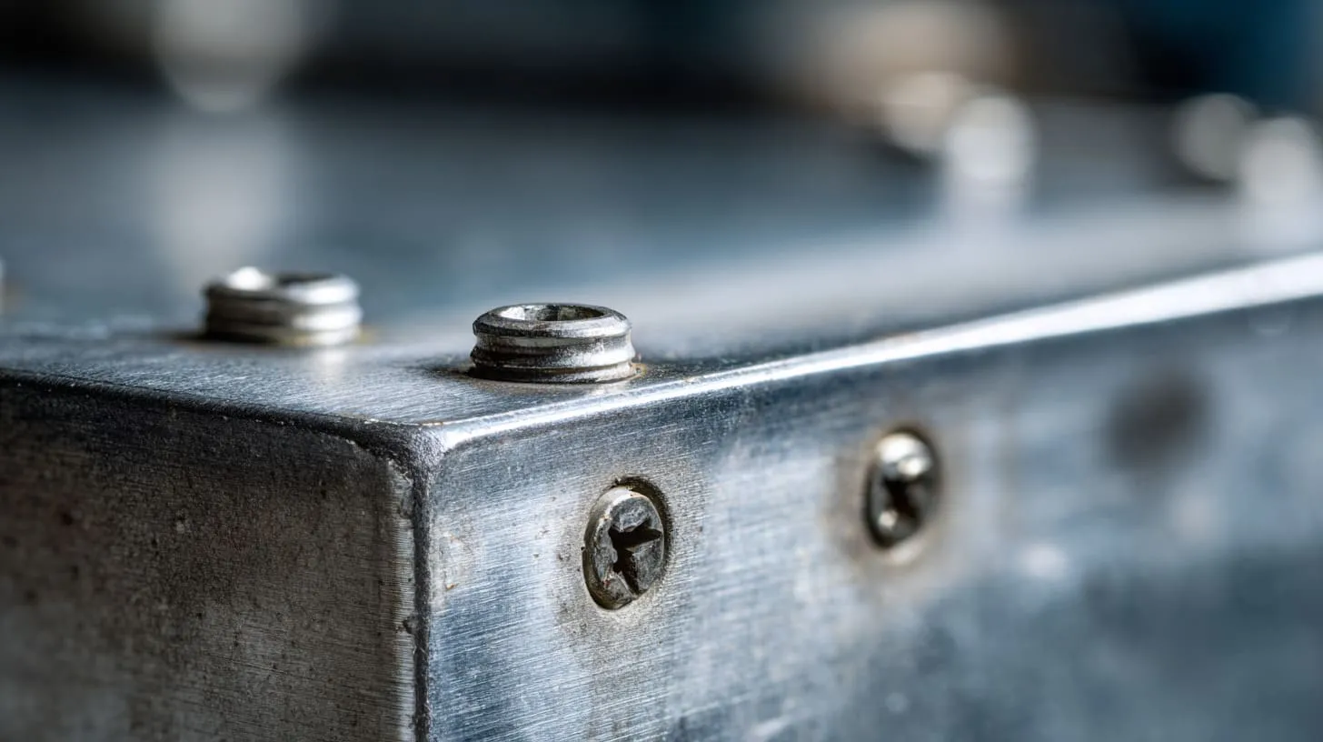
I think this is where many good-looking explanations become too tidy. People say metal shields EMI, and that statement is not wrong, but it is incomplete. Metal does not shield well just because it exists. Metal shields well when current can flow across it in a continuous and predictable way.
That sounds technical, but the basic idea is simple. The enclosure needs to behave like one conductive body, not like a group of separate metal pieces that only seem connected.
What makes this more interesting is that many EMI problems do not come from a dramatic hole or a huge design mistake. They come from a weak seam. A bad joint. A coated contact point. A tiny rise in resistance. The sort of thing a person can miss with the naked eye.
When I judge a shielding path, I do not trust the fact that two parts are touching. I care about whether they are touching electrically, not just mechanically.
Continuous conductive path vs. isolated metal parts
A proper shield needs continuity. That means current must be able to move across the enclosure skin with as little interruption as possible. If the top cover, bottom shell, side walls, and fastening zones all share a clean conductive path, the enclosure has a better chance of containing electromagnetic energy.
But if those same parts are separated by resistive coatings, oxide films, loose joints, or poorly designed seams, they stop behaving like one shield. They start acting like separate pieces.
That difference matters more than many people expect.
I often explain it like this: a metal enclosure is not only a shape. It is also a path. If the path is broken, the shape alone will not save you.
| Condition | What it Looks Like | What it Means for EMI |
|---|---|---|
| Continuous bare contact | Metal parts share clean contact areas | Better current flow and stronger shielding |
| Coated contact zones | Parts touch through insulating finish | Weak continuity and higher leakage risk |
| Loose or uneven joint | Contact only at scattered points | Unstable shielding behavior |
| Mixed surface condition | Some areas conductive, some blocked | Inconsistent test results |
This is why I get uncomfortable when people say, “It is aluminum, so it should shield well.” That sentence skips the most fragile part of the story.
Contact resistance at seams and joints
Seams and joints are where theory meets real life. In a drawing, a joint looks simple. Two parts meet. A screw pulls them together. Job done. On a workbench, it is rarely that clean.
Real contact depends on pressure, flatness, roughness, finish thickness, fastener position, and surface condition. If any of those go wrong, contact resistance goes up. Once resistance goes up, shielding performance can drop.
This part deserves respect because seams are often the weak line of the whole enclosure.
I have looked at enclosures that felt very solid in the hand and still had poor electrical contact along the mating edge. That happens because mechanical confidence can fool people. A lid that feels secure is not always a lid that conducts well along the full seam.
Here is a simple way I look at it:
| Seam Condition | Mechanical Feel | Electrical Reality |
|---|---|---|
| Tight, bare, flat seam | Strong | Usually reliable |
| Tight but anodized seam | Strong | Often poor |
| Loose seam with few fasteners | Weak | Weak |
| Tight seam with gasket support | Strong | Often much better if designed well |
A seam is not judged by how hard it is to pry open. A seam is judged by whether it gives current a stable way to cross.
Skin effect and high-frequency behavior
This is the point many teams underestimate. At higher frequencies, current tends to flow on the surface of a conductor, not deep inside it. That means the outer layer matters a lot.
So even if the base aluminum is highly conductive, the surface condition still controls what the current experiences first. That is why an insulating finish can do so much damage. The shield does not get to “skip” the surface and use the bulk metal like nothing happened.
That is also why I think finish choice should never be treated as a pure cosmetic issue on EMI-sensitive products. The surface is the battlefield.
| Factor | Low Frequency View | High Frequency View |
|---|---|---|
| Base metal conductivity | Important | Important |
| Surface finish | Moderate concern | Very high concern |
| Seam contact quality | Important | Critical |
| Tiny gaps and barriers | Sometimes tolerated | Often much more harmful |
The funny thing is that high-frequency problems often come from very ordinary factory decisions. A thicker coating. A finish change. A different washer. A small tolerance shift. Nothing dramatic. Still enough to change the result.
That is why surface treatment deserves a closer look, and anodizing is usually the first finish I want to question.
How Does Anodizing Change the Electrical Behavior of Aluminum?
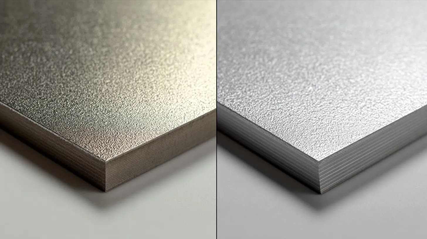
Anodizing is one of those finishes people like for good reasons. It looks neat. It improves wear resistance. It helps corrosion performance. It gives aluminum a more finished, more professional feel. I understand why so many customers ask for it.
I also understand why EMI engineers get nervous when they hear that request.
The problem is not that anodizing is bad by itself. The problem is that it changes the electrical behavior of the aluminum surface in a way that many non-EMI buyers do not expect. It turns a naturally conductive metal surface into a controlled insulating layer. That one change can reshape the performance of the whole enclosure.
What makes me pause on real projects is not the color or finish class. It is whether the anodized layer is sitting on the exact spots where the current path needs to stay alive.
Formation of oxide layer (Al₂O₃)
Anodizing works by building up an oxide layer on the aluminum surface. That oxide layer is hard, useful, and protective. It also behaves more like a ceramic than like raw aluminum.
That detail matters a lot.
Because once that layer forms, the outer surface no longer acts like exposed conductive aluminum. It acts like an electrically resistant barrier. The thickness can vary, and even small thickness values can matter when the job depends on reliable contact across seams or fastener areas.
I think this is where people get caught. The enclosure is still “aluminum” in a materials list, but the surface seen by the joint is no longer really acting like bare aluminum.
| Property | Bare Aluminum | Anodized Aluminum |
|---|---|---|
| Surface conductivity | High | Very low |
| Wear resistance | Lower | Higher |
| Corrosion resistance | Moderate | Better |
| EMI contact friendliness | Better | Riskier |
That contrast is the whole point of this article.
Electrical insulation vs. base metal conductivity
This is the heart of the issue. Aluminum under the finish is conductive. The finish itself is not. So the enclosure becomes a strange mix of good conductor underneath and poor contact layer outside.
That can fool a team into false confidence.
A buyer hears “aluminum enclosure” and expects shielding. An engineer sees a metal housing and feels safe. A sourcing team approves anodizing because it solves appearance and corrosion needs. No one stops to ask the harder question: can the mating surfaces still conduct where they need to?
I have seen that missed question create more trouble than any dramatic design failure.
Here is the simple version:
- Base aluminum gives you shielding potential.
- Anodized surface can block that potential.
- Joint design decides whether the shield works in practice.
That last point is why I never separate finish choice from joint strategy.
Variation by anodizing type (Type II vs Type III)
Not all anodizing behaves the same. Type II anodizing is usually thinner. Type III, often called hard anodizing, is usually thicker and tougher. From a wear and durability point of view, that can sound attractive. From an EMI point of view, it often means more trouble.
A thicker insulating layer usually makes conductive contact harder, not easier.
This does not mean Type III is always impossible on EMI-sensitive products. It means the design must compensate more carefully. Contact areas may need masking. Hardware choices may need improvement. Post-processing may be necessary. The project becomes less forgiving.
| Anodizing Type | Typical Character | EMI Impact |
|---|---|---|
| Type II | Thinner decorative/protective layer | Still risky for contact areas |
| Type III | Thicker hard protective layer | Usually worse for conductive continuity |
That is why I do not ask only, “Is it anodized?” I also ask, “What kind, how thick, and where?”
Once that layer reaches the seam, the problem stops being abstract. It becomes painfully practical.
Why Can Anodized Surfaces Break EMI Shielding at Seams?

This is where things get real. A seam is not a theory topic. A seam is where the enclosure either acts like one shield or fails to do so.
I have seen teams spend a lot of energy on enclosure shape, wall thickness, vent placement, and grounding plans, then lose performance because the seam itself could not carry current well. That result feels annoying because the seam often looks fine. It may even look excellent.
But looks are cheap in EMI work.
The issue is simple: anodized surfaces can sit between mating parts and stop true metal-to-metal contact from happening. Once that happens, the seam becomes a weak line instead of a conductive bridge.
The part that makes me cautious is how often a seam can pass visual inspection while quietly failing its electrical job.
Loss of metal-to-metal contact
A seam works best when exposed conductive metal areas meet each other under good pressure. Anodizing interrupts that contact. The oxide layer acts like a barrier between the two aluminum parts.
That means the parts may be mechanically joined but electrically separated.
I think this is one of the most common misunderstandings in enclosure work. People assume screws will “solve” the problem. They assume clamping force will overcome the finish. Sometimes it helps a little. Often it does not solve enough.
A screw can pull two parts together. It cannot magically turn an insulating layer into a good conductor.
| Seam Setup | Metal Touching Metal? | EMI Confidence |
|---|---|---|
| Bare masked seam | Yes | High |
| Fully anodized seam | No, or very weakly | Low |
| Anodized seam with serrated hardware only | Partial, inconsistent | Medium to low |
| Anodized seam with proper masking + hardware | Yes where needed | Much better |
That is why I never treat “assembled tightly” as proof of continuity.
Micro-gaps and inconsistent pressure
Even when hardware is present, contact can still be poor. Real surfaces are not perfectly flat. Finishes add thickness. Parts have tolerances. Pressure is not always even from one end of the seam to the other.
The result is ugly in a subtle way. One small part of the seam may contact reasonably well. Another part may barely contact at all. This creates local weak points, and weak points are exactly where EMI leakage likes to show up.
I have seen this happen most often on longer covers with limited fasteners. The middle area becomes less stable. The seam still looks closed. The electrical behavior is a different story.
A practical way to think about it is this:
- Surface roughness changes real contact area
- Coating thickness changes the gap behavior
- Screw spacing changes contact pressure distribution
- Part flatness changes whether the seam shares load evenly
That combination is why “almost touching” is not enough.
Real-world failure scenarios
The most frustrating failures are the quiet ones. The enclosure looks premium. The anodized color is beautiful. The machining is clean. The logo is sharp. Then the EMC test report points to seam leakage.
That kind of failure teaches a painful lesson. Cosmetics can pass inspection faster than conductivity can.
I remember a case that looked perfect to the customer during the sample stage. The team felt confident because the parts fit well and the product felt solid. But the finish covered every mating area. The fastener count was modest. The seam path was too dependent on chance contact. The enclosure looked expensive and performed like a compromise.
That kind of outcome is not rare.
| Failure Pattern | Why It Happens |
|---|---|
| Seam leakage near corners | Poor pressure distribution or weak contact area |
| Leakage near long cover edges | Too few fasteners or coated mating surfaces |
| Inconsistent test results | Contact path changes with torque, handling, or assembly variation |
| Last-minute redesign | Finish was chosen before EMI path was planned |
That is usually the moment when teams start asking a bigger question: is anodizing the only risky finish, or is the real problem broader than that?
Are All Surface Finishes Problematic for EMI Shielding?
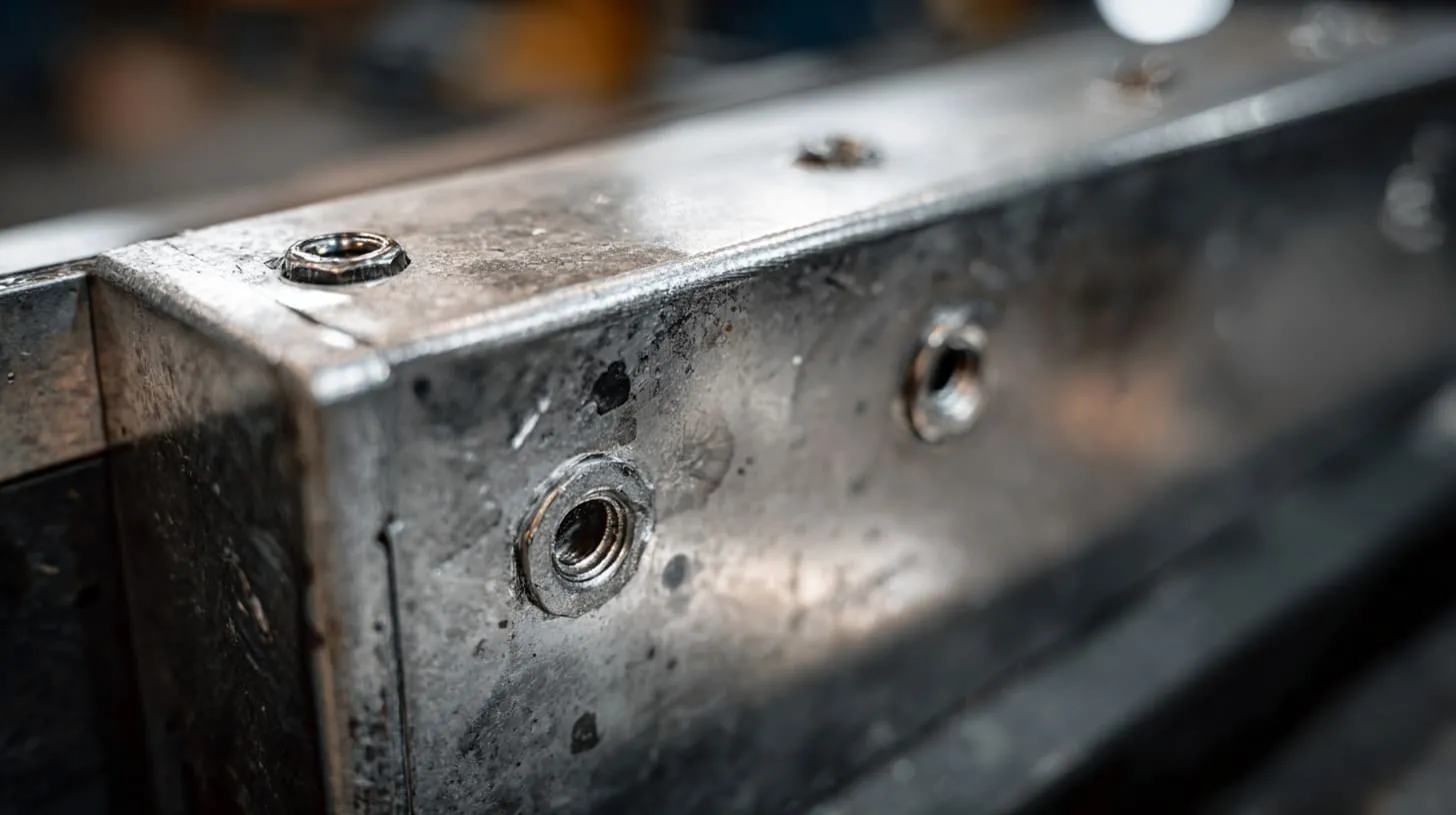
It would be too easy to blame anodizing alone. The truth is wider than that. Many surface finishes can hurt EMI performance if they sit on the wrong areas. Anodizing gets a lot of attention because it is so common on aluminum enclosures, but it is not the only finish that creates trouble.
Paint can do it. Powder coating can do it. Thick non-conductive seal layers can do it too.
So I do not think the right question is, “Is anodizing bad?” I think the better question is, “What is this finish doing to the conductive path I need?”
That small shift in thinking helps a lot.
When I compare finishes, I do not start with appearance. I start with whether the seam, contact zone, and hardware path can still do their job after the finish is applied.
Comparison of common finishes
Different finishes serve different goals. Some mainly protect. Some mainly improve appearance. Some help both. But from an EMI angle, the important issue is whether the finish supports conductivity or blocks it.
Here is how I tend to view common options:
| Finish Type | Corrosion Protection | Appearance | Surface Conductivity | EMI Risk |
|---|---|---|---|---|
| Bare aluminum | Low to moderate | Plain | High | Low |
| Anodizing | Good | Good to excellent | Low | High |
| Powder coating | Good | Good | Very low | High |
| Painting | Moderate to good | Good | Very low | High |
| Nickel or tin plating | Good | Industrial | High | Lower |
| Conductive conversion coating | Moderate | Plain | Better than anodizing | Lower |
That table is not a universal ranking for all products. It is just a practical reminder that finishes solve one problem while sometimes creating another.
And this is exactly why I dislike one-dimensional decisions in sourcing. A finish that wins the cosmetic discussion can lose the EMC discussion badly.
Trade-off between corrosion resistance and conductivity
This trade-off is real. Better protection often comes with worse surface conductivity. That does not mean the protective finish is the wrong choice. It means the design cannot be lazy.
A buyer may want strong corrosion resistance for outdoor use. An engineer may want low contact resistance for shielding. Both needs can be valid. The mistake is pretending they do not fight each other.
That tension is where real engineering judgment starts.
I usually get more cautious when someone says, “We need the whole enclosure fully coated for durability.” That sentence may be fine for a non-EMI box. For an EMI-sensitive enclosure, it is often the start of trouble unless contact zones are protected by design.
| Project Need | Easy Finish Choice | Hidden EMI Cost |
|---|---|---|
| Premium look | Anodizing or paint | Contact loss at seams |
| Tough wear resistance | Hard anodizing | Worse continuity |
| Outdoor durability | Full coating coverage | Masking becomes more critical |
| Fast low-cost production | Standard powder coat flow | EMI redesign later |
The hard part is not choosing one goal. The hard part is balancing the goals without letting one of them quietly wreck the others.
That is why the next question matters so much: once anodizing is already part of the project, how do engineers bring conductivity back where it matters?
How Do Engineers Restore Conductivity in Anodized Enclosures?

This is the part I like most, because it moves the conversation from fear to control. Anodizing does not automatically kill a project. It just means the design has to respect what the finish is doing.
The smartest teams do not argue with the physics. They work around it. They protect visible surfaces where appearance matters, and they preserve conductive paths where shielding matters. That balance is usually possible, but it must be planned on purpose.
I trust a finish plan much more when it tells me exactly where conductivity is being restored, not just where color and protection are being added.
Selective masking of contact areas
Masking is one of the most useful solutions. The idea is simple. Keep anodizing off the mating surfaces, screw contact zones, grounding pads, or other spots that must stay conductive.
That way, the enclosure can still have anodized visible faces while the critical electrical paths remain bare.
This sounds easy on paper. In real manufacturing, it needs discipline. The masked areas must be placed correctly. They must be large enough. They must line up with the true contact points, not just with the drawing ideal.
I have seen masking specified too narrowly, which creates a false sense of safety. A tiny bare strip that misses the real pressure zone does not help much.
| Masking Approach | Benefit | Risk if Done Poorly |
|---|---|---|
| Masked seam flange | Restores seam continuity | Misalignment reduces value |
| Masked screw seating area | Improves hardware contact | Too small an area limits effect |
| Masked grounding point | Better bonding path | Post-finish contamination can still hurt contact |
Masking is not glamorous, but it saves projects.
Use of conductive gaskets and EMI fingers
Sometimes masking alone is not enough. Long seams, complex covers, removable panels, and high-frequency requirements may need extra support. That is where conductive gaskets, metal finger stock, and similar solutions become useful.
These parts help bridge tiny gaps and improve continuity along the seam. They also help when enclosure surfaces are not perfectly flat or when repeated opening and closing is part of the product life.
I do not treat conductive gaskets as magic. I treat them like tools. They can help a lot, but only when the surrounding design gives them the right compression, alignment, and contact environment.
A poor gasket design can be just as disappointing as a poor seam.
| Conductive Aid | Best Use | What I Watch For |
|---|---|---|
| Conductive elastomer gasket | Controlled compression seam | Compression set and fit tolerance |
| Finger stock | Removable panels and service covers | Wear, position, installation quality |
| Conductive foam | Lower-cost gap support | Durability and contact stability |
The hidden question is always the same: is the part really carrying current, or is it only filling space?
Fastener strategy optimization
Fasteners matter more than many people expect. Screw count, screw spacing, washer type, torque control, and seating geometry all change how the seam behaves electrically.
A smart fastener plan can improve a borderline enclosure a lot. A weak fastener plan can ruin a good material and finish choice.
I become more suspicious when I see long seam lengths with few screws and full anodizing on the mating path. That combination often asks too much from too little hardware.
A few common tactics help:
- Increase screw density on longer seams
- Use serrated or star washers where appropriate
- Make sure hardware bites into conductive zones
- Control torque so contact is consistent
- Avoid relying on one or two fasteners to carry the whole continuity story
| Fastener Choice | Effect on Contact |
|---|---|
| More screws, shorter spacing | Better pressure distribution |
| Serrated washer | Can break through light barriers or improve bite |
| Poor torque control | Creates inconsistent contact |
| Decorative hardware only | May look good but add little electrical value |
The details here are not glamorous, but they separate a design that merely closes from a design that shields.
And once I see how many fixes are needed, I start asking a harsher question: what mistakes created the problem in the first place?
What Design Mistakes Commonly Lead to EMI Failure?
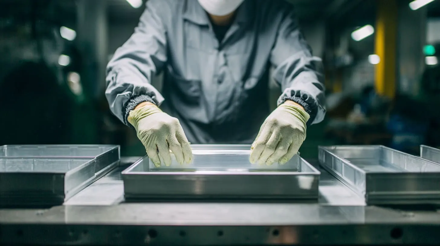
Most EMI failures tied to finish are not mysterious. They usually grow out of very ordinary assumptions. That is why they are so common. Nobody makes them because they want a bad result. They make them because the logic feels harmless in the moment.
The enclosure is metal. The cover fits. The finish is premium. The supplier says it is standard. So the team moves on.
That sequence sounds normal. It is also where trouble begins.
The design mistake I see most often is not a lack of effort. It is confidence placed in the wrong details.
Assuming “metal enclosure = good shielding”
This mistake shows up everywhere. A team chooses aluminum and feels that the EMI box is checked. But a metal enclosure is only the starting condition. It is not the final answer.
If the conductive path is broken by finish, seam design, or contact resistance, the enclosure stops behaving like the shield people imagined.
I think this assumption survives because it sounds reasonable. It is half true. And half true is dangerous in engineering.
| Assumption | Reality |
|---|---|
| Metal always shields well | Only if continuity is maintained |
| Aluminum guarantees EMI success | Surface condition can ruin it |
| Strong assembly means strong EMI | Mechanical feel and electrical performance differ |
That difference is where many redesign bills are born.
Over-reliance on screw pressure
Another common mistake is trusting clamping force too much. A screw can improve contact. But screw pressure is not a cure for every finish problem. If the seam surfaces are insulated, uneven, or poorly planned, the pressure may still produce weak or scattered contact.
I have seen people tighten harder when the real problem was finish on the seam. That is like pressing two gloves together and hoping they become one hand.
A better question is not, “Are the screws tight?” It is, “What exactly are the screws pressing together?”
Ignoring coating thickness tolerance
Coating thickness sounds like a small production detail until it starts affecting fit, contact, and hardware seating. Then it becomes a project issue very quickly.
Different finish thicknesses can change:
- how parts mate
- how seams sit
- how washers bite
- how consistent the contact path becomes
This matters even more on precision enclosure projects where the seam geometry is already tight.
I get wary when the drawing is precise but the finish discussion is vague. That usually means the team has not fully connected appearance requirements to electrical performance.
| Overlooked Variable | Result |
|---|---|
| Finish too thick on mating edges | Reduced or lost conductivity |
| Uneven coating build-up | Inconsistent seam pressure |
| Tolerance stack-up ignored | Fit problems and unstable assembly |
Lack of EMC validation during design phase
This mistake is expensive because it delays learning. When EMI-related finish risks are ignored early, the team often discovers them after samples, after tooling choices, or even after certification testing starts.
That timing hurts.
I prefer ugly questions early over expensive surprises late. A rough technical conversation before finishing is much cheaper than reworking completed parts after a failure.
Useful checks during design include:
- identify all critical conductive paths
- mark masking areas clearly
- define finish type and thickness
- review fastener spacing
- decide whether gasket support is needed
- test continuity assumptions before final release
The real pain of EMI failure is not only technical. It is commercial too. Delays frustrate buyers. Redesign burns trust. And that leads naturally to the next issue: how buyers should judge these finish decisions before approving a supplier.
How Should B2B Buyers Evaluate Surface Finishes for EMI Applications?
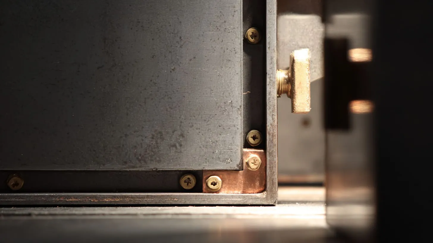
I think buyers often get trapped between two kinds of pressure. One side wants the enclosure to look polished and durable. The other side needs it to perform well in the real product. Those goals can support each other, but they can also clash hard if nobody asks the right questions.
For B2B buyers, this is not a small detail. A finish problem can mean failed tests, delayed shipments, and awkward customer conversations. That is why I think buyers should evaluate finishes with more skepticism, especially when EMI matters.
What usually tells me a buyer understands the risk is not the finish they choose, but the questions they ask before they approve it.
Ask the right technical questions
Many finish problems can be exposed early with a few direct questions. Not fancy questions. Just the right ones.
I would ask things like:
- Are the mating surfaces masked?
- Which finish type is being used?
- How thick is the finish?
- Are the contact paths defined in the drawing?
- Is there continuity validation after finishing?
- Are conductive gaskets or special washers required?
Those questions change the conversation. They move the project away from color cards and toward functional reliability.
| Buyer Question | Why It Matters |
|---|---|
| Is masking used on contact surfaces? | Shows whether continuity is planned |
| What finish type is specified? | Not all finishes affect EMI the same way |
| Has this finish been used on EMI projects before? | Reveals supplier experience |
| How is the seam conductivity protected? | Forces practical design discussion |
A supplier who cannot answer these clearly may still be good at machining, but that does not mean they are good at EMI-aware enclosure work.
Balance aesthetics, durability, and performance
This balance is where many projects get emotional. People like products that look finished. They want color consistency. They want wear resistance. They want the enclosure to match the brand.
I understand that completely. I work in real business, not in a lab fantasy.
But the better-looking finish is not always the better product choice. Sometimes the right decision is a slightly less perfect-looking contact zone that gives the product a much stronger shielding path.
I often think the smarter buyer is the one willing to accept a controlled visual compromise in hidden areas to protect the product’s real function.
| Priority | Easy Choice | Smarter Choice for EMI Projects |
|---|---|---|
| Full premium appearance | Coat everything evenly | Keep hidden contact areas functional |
| Max durability | Choose the hardest finish everywhere | Protect visible zones, engineer contact zones |
| Fast approval | Accept supplier standard process | Review finish against electrical needs |
That kind of thinking usually saves pain later.
Work with suppliers who understand EMC
This part matters more than people like to admit. A supplier can be fast, cheap, and responsive, yet still be the wrong partner for an EMI-sensitive enclosure if they do not understand conductive paths.
I do not mean they need to be EMC specialists in the pure laboratory sense. I mean they need to understand the relationship between finish, seam, hardware, and continuity well enough to flag a bad decision before production.
That ability saves time. It saves samples. It saves reputation.
A useful supplier should be able to help with:
- masking recommendations
- finish-risk discussion
- seam structure advice
- hardware suggestions
- process checks after finishing
That is why I think buyers should not only ask for quotation. They should ask for judgment.
Once the buyer starts thinking that way, the next step becomes much clearer: what finish strategies make more sense from the beginning?
What Are Better Surface Finish Strategies for EMI-Sensitive Projects?
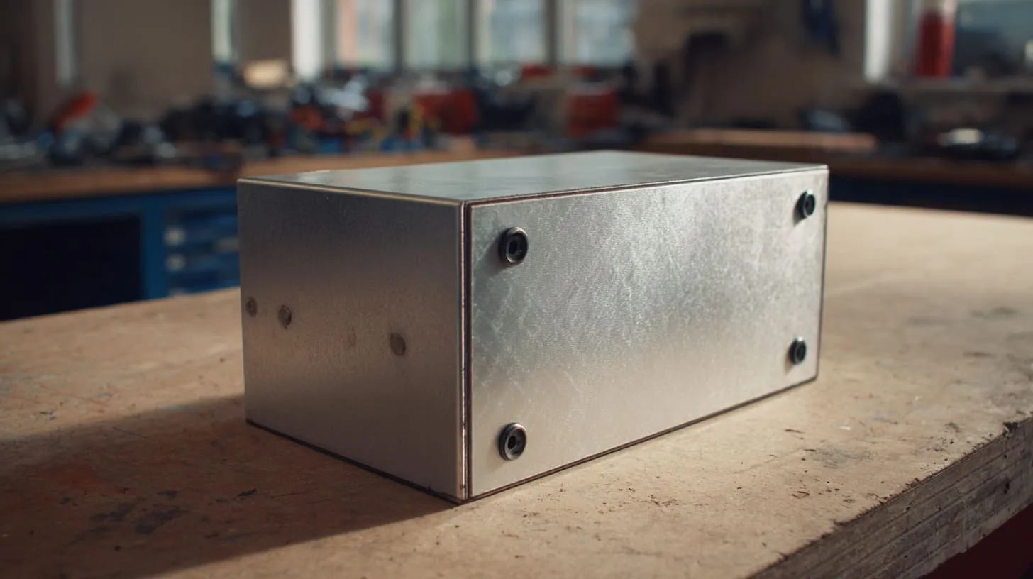
I do not believe in one universal finish formula. Different products face different environments, budgets, and appearance goals. Still, some strategies are much more sensible than others when EMI matters.
The best ones usually share one idea: protect what needs protection, and preserve conductivity where the shield needs to work.
That sounds obvious. It also gets ignored far too often.
The finish plan I trust most is the one that makes clear which surfaces are cosmetic, which are environmental, and which are electrical.
Hybrid finishing approach
This is often my favorite approach. Use anodizing or another protective finish on visible external areas, but keep key contact zones bare or specially treated. That way the enclosure can still look professional while the shield path remains alive where it matters.
I like this method because it respects both business reality and engineering reality.
The outside can serve the brand. The inside joint can serve the physics.
| Area of Enclosure | Best Finish Logic |
|---|---|
| Visible outer surfaces | Anodize or protect for appearance and durability |
| Hidden seam flanges | Leave conductive or mask before finishing |
| Grounding points | Preserve clean electrical contact |
| Fastener seating zones | Design for consistent conductive bite |
This kind of split strategy often feels more mature than all-or-nothing finishing.
Conductive conversion coatings
When corrosion resistance is needed but full insulation is risky, conductive conversion coatings can be a better path. They usually do not look as decorative as anodizing, but they can preserve conductivity much better.
That makes them useful on EMI-sensitive assemblies, especially where the enclosure must keep more conductive surface behavior.
The trade-off is simple. You may give up some of the premium visual feel. In return, you often gain a more EMI-friendly contact condition.
That is not always the right answer. But it is often a smarter answer than decorative anodizing applied without discipline.
Post-processing for contact surfaces
Sometimes the finish is already chosen and cannot be changed easily. In those cases, post-processing can help. Machining, grinding, or other controlled rework on contact areas can restore exposed metal where the conductive path is needed.
I see this as a rescue strategy or a controlled design method, depending on how early it is planned.
It works best when it is intentional. If it becomes a last-minute patch after test failure, it often costs more and creates more variation risk.
| Strategy | Strength | Weakness |
|---|---|---|
| Hybrid finishing | Strong balance | Needs planning discipline |
| Conductive conversion coating | Better continuity | Less decorative look |
| Post-machining contact areas | Restores path | Adds process cost and control needs |
What matters most is honesty. A finish strategy must admit what the product is trying to do. If EMI performance is critical, the conductive path must be designed like a first-class feature, not treated like an afterthought.
And that is exactly why I hold the view I do.
Conclusion
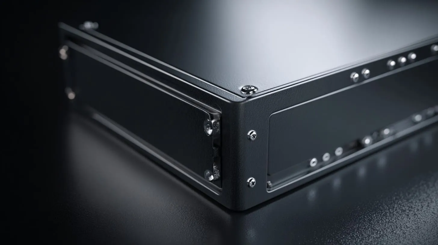
I see surface finish as an electrical decision, not only a cosmetic one. That is why I take it seriously on EMI-sensitive enclosure projects. I have seen too many cases where a beautiful finish created a weak shield, and the problem only became visible after time, money, and confidence had already been spent.
My view comes from the way these projects fail in real life. The material choice can be correct. The machining can be good. The assembly can feel solid. Still, if the conductivity path is blocked by anodizing in the wrong places, the enclosure stops behaving like a reliable shield. That is why I do not judge a finish by appearance alone. I judge it by what it does to seams, joints, fasteners, and contact zones.
I think that is the right way to look at it because EMI does not reward wishful thinking. It rewards continuity. It rewards careful contact design. It rewards teams that accept trade-offs early instead of hiding from them until testing forces the truth out.
So yes, anodizing can be useful. I am not against it. I am against using it blindly.
If I choose anodizing on an EMI project, I want a reasoned plan behind it. I want masking where it matters. I want the seam path protected. I want hardware that helps instead of pretending. I want the design to reflect how the enclosure really works, not just how it photographs.
That is also why I believe buyers should ask harder questions, and why suppliers should answer them with real engineering thought, not sales comfort.
If you are working on a custom aluminum enclosure and you need to balance finish, appearance, and EMI performance, feel free to contact me at info@maidatech.com or visit maidatechenclosure.com. I care about these details because they decide whether a box only looks finished, or actually works the way it should.