Skip to content

The first enclosure question I receive is usually a size: “Can you make a 160 × 120 × 75 mm box?” That is a useful starting point, but it is not enough to choose a housing that will work in production. The electronics may fit inside the outer dimensions and still leave no room for a mating plug, an assembly tool, a gasket joint, or a sensible cooling path.
I treat enclosure selection as a system decision. The enclosure has to protect the product, locate its components, route its cables, support its installation, and still be repeatable at the target volume. When those requirements are settled in the right order, the quote and sample are much less likely to bring a surprise.
Start With the Application, Not the Catalog

Before comparing aluminum, plastic, or sheet metal, write down what the finished unit must do. A desktop instrument, a wash-down machine controller, and a pole-mounted outdoor sensor may have similar circuit boards but very different enclosure risks.
Define the conditions around the installed product
Include the location, exposure, operating temperature range, likely contaminants, mounting orientation, service access, target production quantity, and expected product life. Also identify whether the enclosure must satisfy a named customer, market, safety, or test requirement. This turns a vague request for “waterproof” or “rugged” into an engineering brief that a manufacturer can review.
I have learned to ask about installation early. A box that looks excellent on a bench can be awkward on a wall, difficult to open under a machine, or exposed to water at a cable entry that nobody included in the first drawing. Those conditions lead directly to the protection level and construction details you need.
Specify Protection as an Installed System
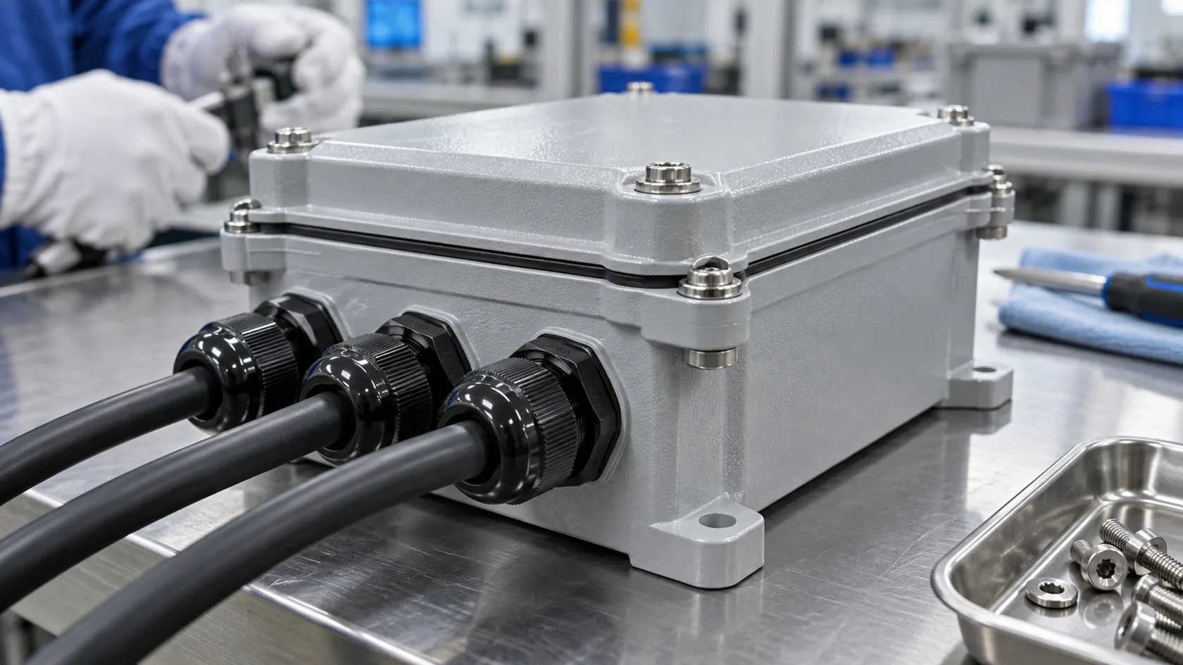
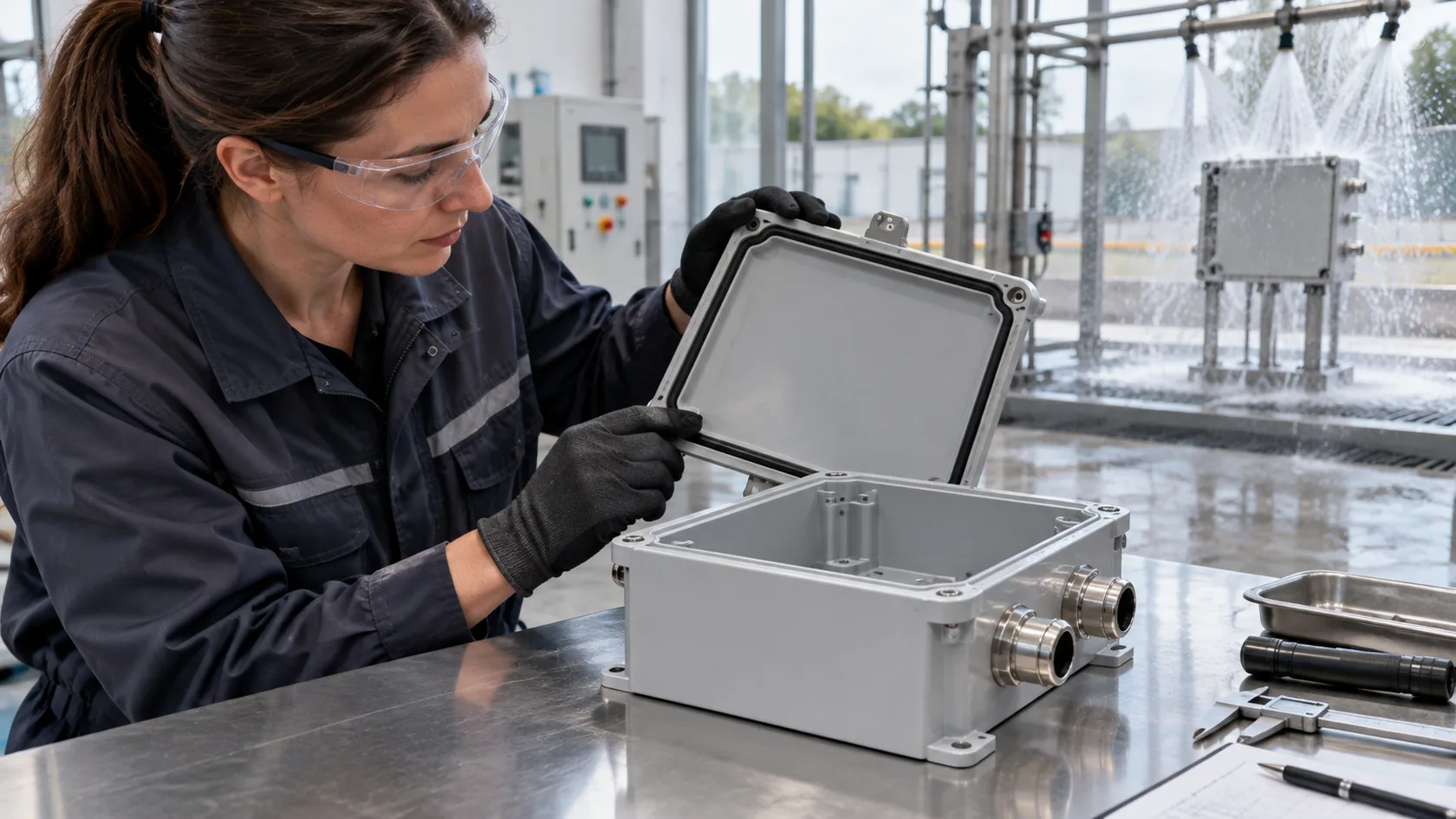
An IP or NEMA designation is not simply a label that can be added to a bare housing. The joint between cover and base, gasket compression, screws, hinges, cable glands, connectors, vents, mounting orientation, and final test configuration all affect the result.
Choose the standard and the actual exposure
IEC 60529 defines IP Code classifications for degrees of protection provided by enclosures. In North American applications, NEMA enclosure-type descriptions are also widely used. Do not assume that an IP number and a NEMA Type are interchangeable; NEMA notes that its types can address additional hazards, so direct conversion is not complete.
| Exposure question | Detail to define | Why it changes the enclosure |
|---|---|---|
| Dust or fibers | Location and cleaning practice | May change cover overlap, gasket, and vent design |
| Rain or wash-down | Direction, pressure, frequency, and installed orientation | Determines joint, cable-entry, and test considerations |
| Corrosive or UV exposure | Chemicals, salt air, sunlight, and maintenance | Influences material, finish, hardware, and validation |
| Condensation | Thermal cycling and internal heat load | May require drainage, breathing, or thermal design choices |
My practical rule is to select the protection target only after the interfaces are named. A correctly rated cable gland cannot compensate for a poorly planned connector, cover joint, or mounting hole. Once the environment is clear, you can choose material and construction on useful evidence rather than habit.
Select a Material for the Real Trade-Off
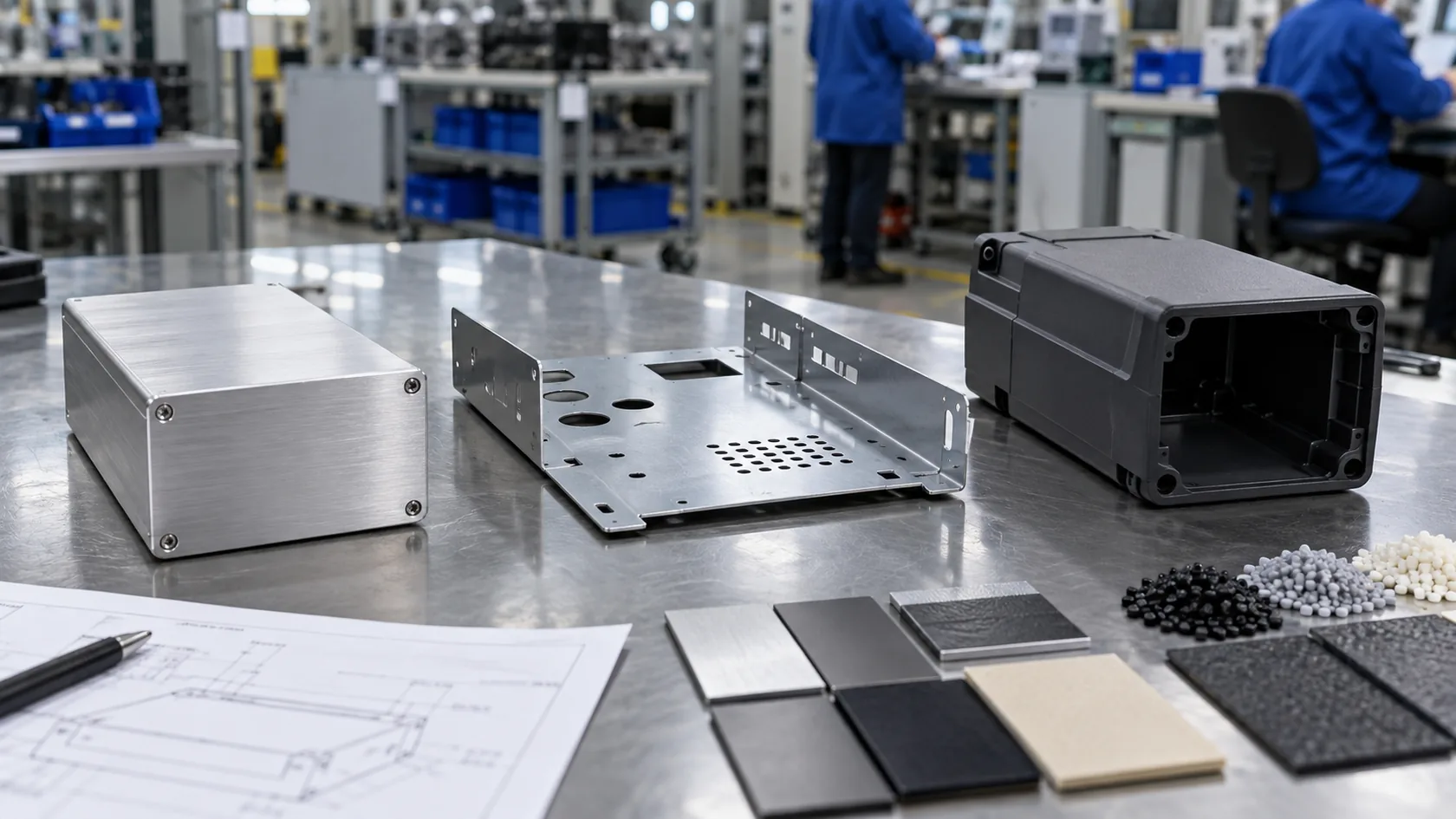
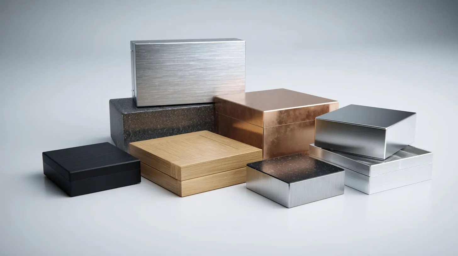
There is no universal “best enclosure material.” Aluminum, steel, stainless steel, and engineering plastics each make sense under different combinations of heat, stiffness, corrosion, appearance, electrical needs, weight, geometry, and cost.
Compare the factors that affect your product
| Material family | Often useful when | Check before deciding |
|---|---|---|
| Aluminum | Low weight, machining, heat spreading, or a premium finished appearance matter | Alloy, wall geometry, corrosion exposure, finish, and electrical-contact needs |
| Sheet steel or stainless steel | Higher structural demand, established panel construction, or demanding corrosion conditions apply | Weight, forming details, finish system, welds, and dissimilar-metal interfaces |
| Plastic | Electrical isolation, complex molded geometry, low weight, or production tooling economics matter | UV and chemical exposure, wall design, heat, impact, and molding constraints |
A powder-coated or anodized aluminum housing can be an excellent choice, but the finish may interrupt a required conductive path unless the grounding or EMI interface is deliberately designed. Plastic can simplify electrical isolation, yet it is not a shortcut around heat, UV, or wall-thickness design. I prefer to decide the material alongside the electrical, thermal, and environmental requirements, not after the outside shape is frozen.
Calculate the Usable Interior, Not Only Outside Size
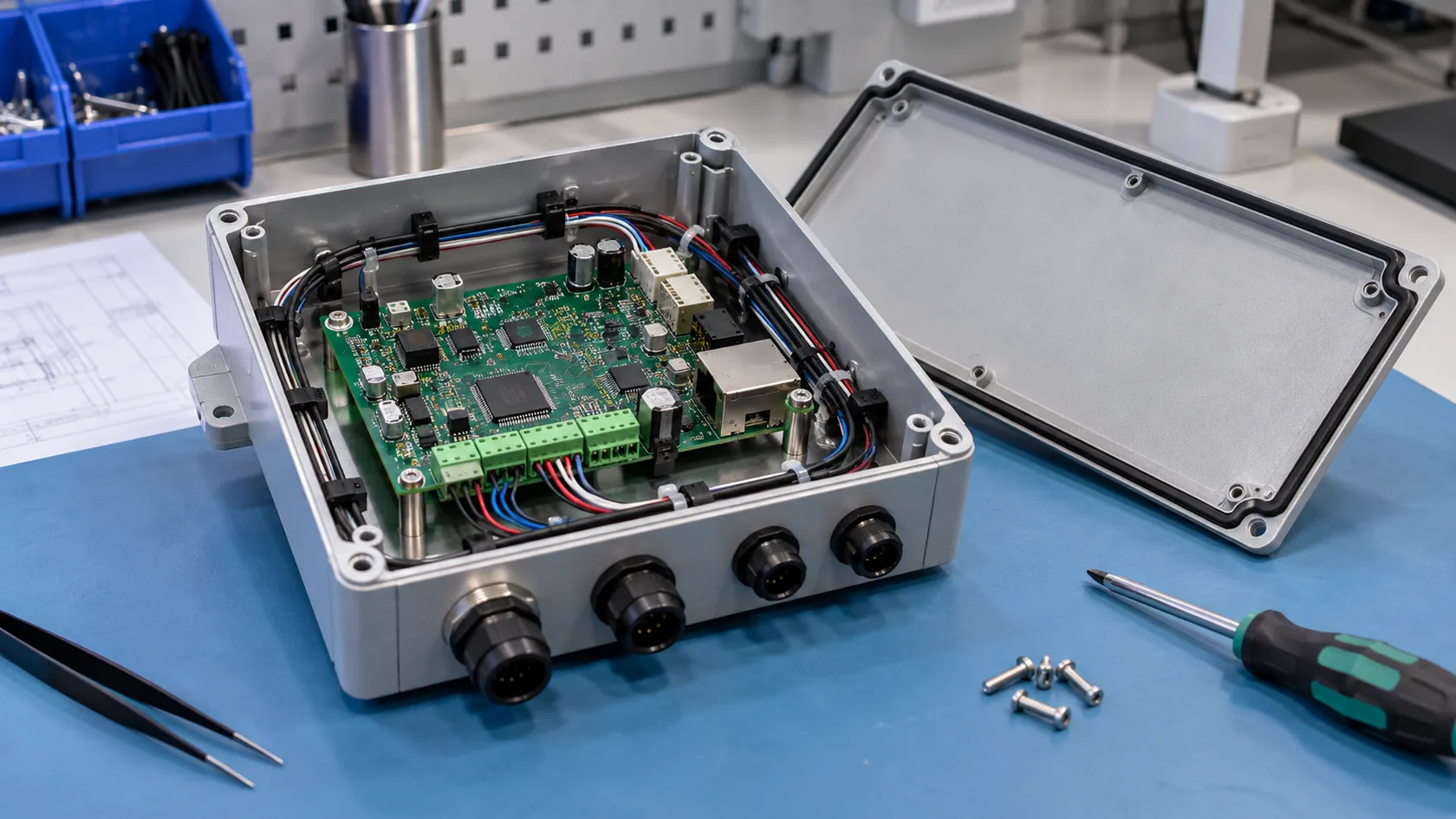
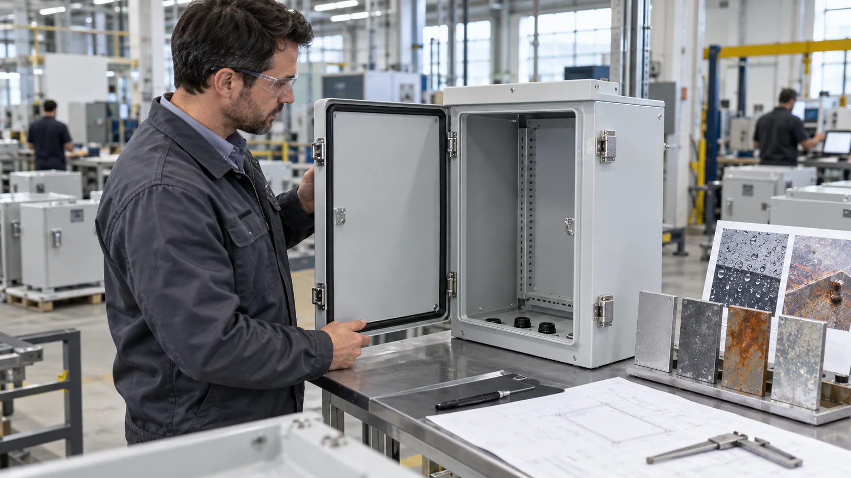
Catalog dimensions describe the outer envelope. The space available to the product is smaller after wall thickness, cover overlap, gasket channels, ribs, standoffs, fasteners, mounting flanges, and wiring access are included.
Map every interface in the assembly
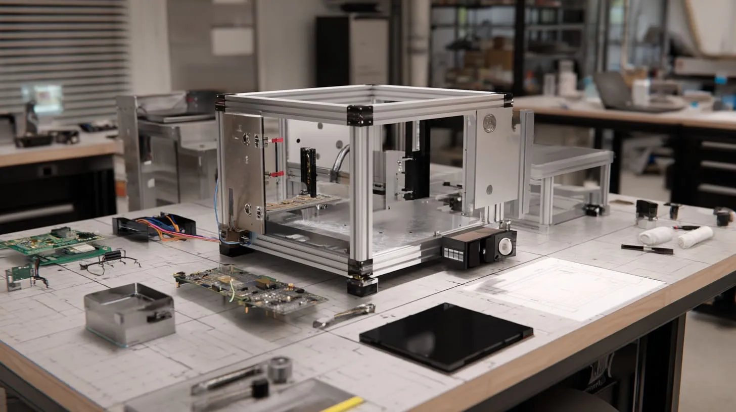
Build a simple layout around the actual PCB, mating connectors, cable diameters, plugs, power parts, battery or display if applicable, and the tools a technician needs to assemble or service the unit. Use dimensioned component data rather than a visual approximation from a 3D model.
| Interface | Question to check | Common late discovery |
|---|---|---|
| PCB and standoffs | Which datums locate the board? | Holes do not align after the production board arrives |
| Connectors | What is the full plugged-in envelope and cable bend? | The connector fits the cutout, but the plug cannot be used |
| Lid and fasteners | Is there tool clearance and a controlled sealing path? | A screw or gasket clashes with the internal assembly |
| Mounting | What clearance is required behind and beside the installed unit? | A wall, rail, or bracket blocks cable routing or access |
This is usually where I find the important millimeters. Reserving them before the first sample is cheaper and cleaner than enlarging one panel after the tooling, machining program, or finish plan is underway.
Design the Thermal Path and the Seal Together

Heat management and environmental sealing are often treated as separate tasks. In reality, the choice to close every opening can reduce airflow and change internal temperatures, while a vent or fan can change the protection and contamination strategy.
Ask where heat goes in normal operation
List the heat-generating components, ambient conditions, permitted internal temperatures, duty cycle, and installation clearance. A conductive path into an aluminum housing may help in one layout, while a sealed plastic housing may require a different arrangement, thermal interface, or electronics derating. Do not promise a temperature result from a material name alone; the component layout, contact area, wall geometry, ambient conditions, and validation method matter.
I also check what happens after the unit cools down. A sealed enclosure that avoids direct water entry can still face condensation during thermal cycling. The right answer might be a gasketed design with a chosen cable-entry arrangement, a protected vent, drainage in an appropriate orientation, or a different thermal architecture—but it must be reviewed as one system.
Choose the Manufacturing Process With Volume in Mind
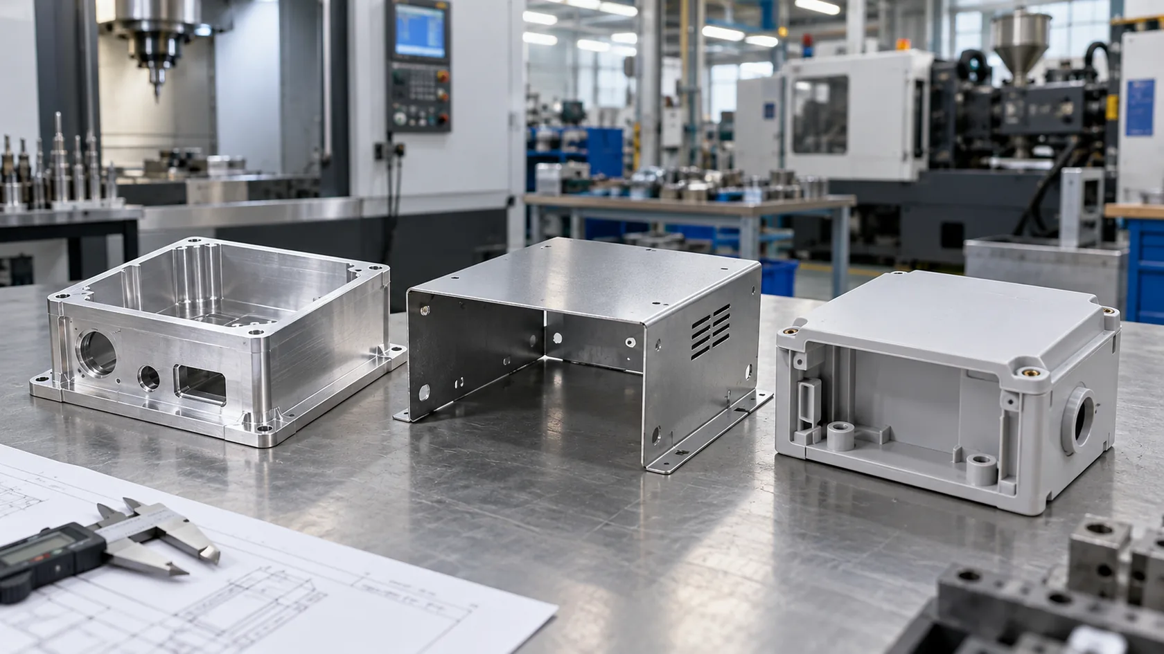
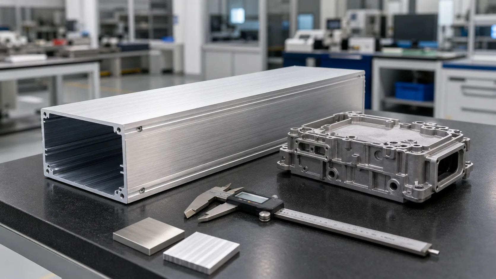
The same enclosure outline can be made through CNC machining, bent sheet metal, aluminum extrusion with machined panels, die casting, or injection molding. The best process depends on more than the part size: geometry, surface requirement, redesign risk, assembly strategy, tolerances, and annual demand all matter.
Keep prototype flexibility separate from production economics
For a pilot or changing design, CNC machining or sheet metal can often accommodate updates without dedicated hard tooling. For a stable higher-volume program, molding or die casting can become appropriate if the part is designed for the tool and its investment is justified. Protolabs’ electronic-enclosure manufacturing overview is a useful starting comparison of several routes.
In sheet metal, bend radii, reliefs, tool access, joining, and the sequence of formed features can determine whether a drawing is simple to build. In molded plastic, draft, wall consistency, ribs, gates, and ejection are design inputs, not factory afterthoughts. I would rather use a sensible prototype route for one more iteration than force an unstable design into expensive tooling too soon.
Put Tolerances Where Parts Must Locate, Seal, or Mate
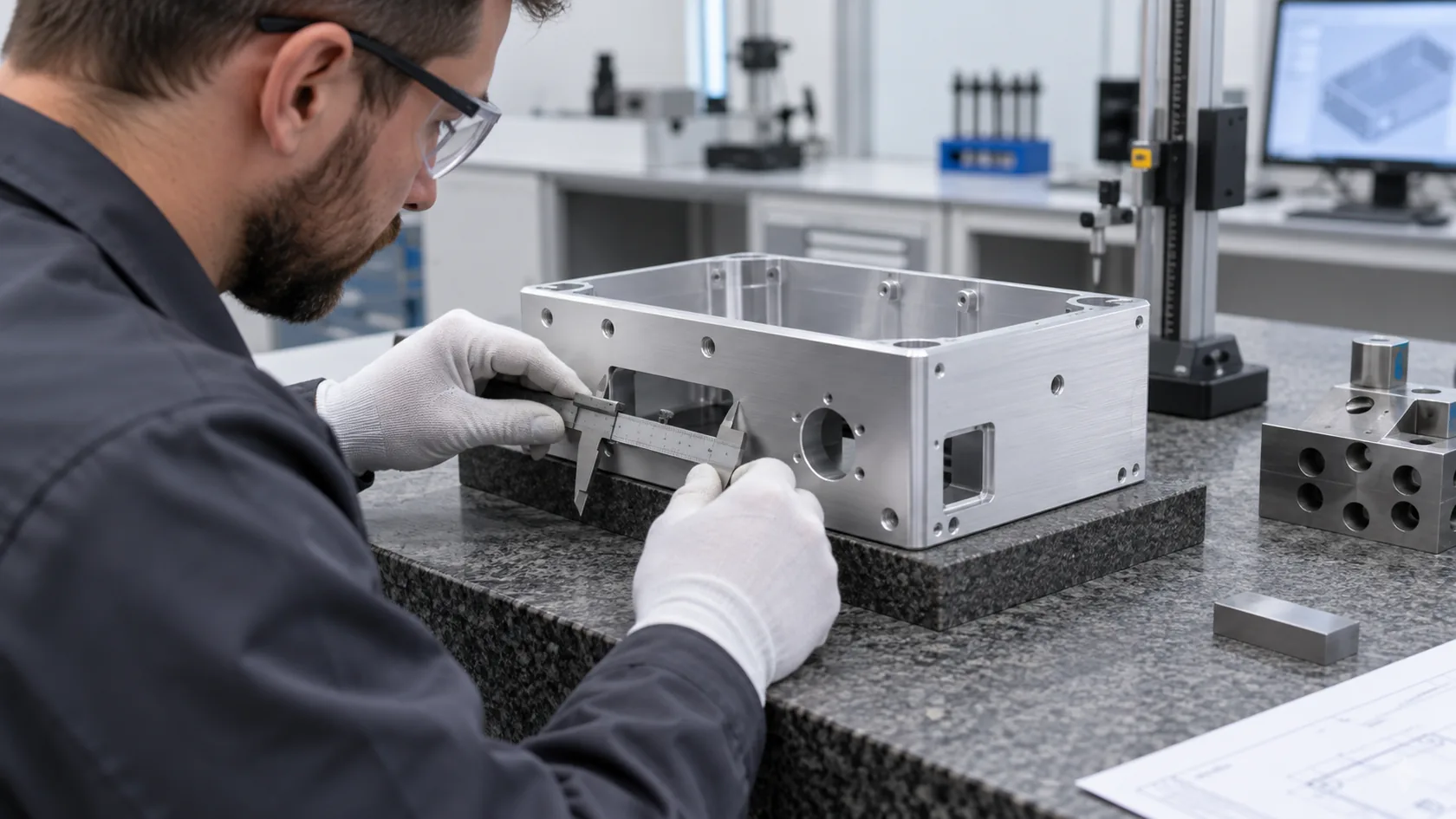
Nominal dimensions describe intent; tolerances describe what variation real production parts can have and still work. Tightening every dimension raises cost and inspection effort, but leaving critical relationships uncontrolled can create a connector, gasket, or mounting failure.
Establish functional datums
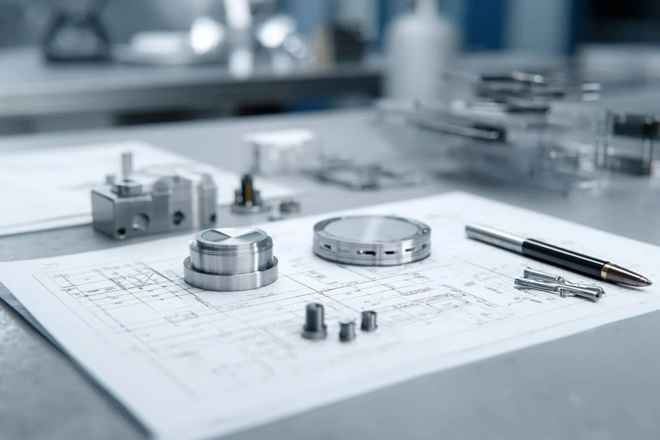
Use datums to control the relationships that matter: PCB mounting holes to front-panel cutouts, cover faces to gasket lands, rail clips to a mounting plane, or an external connector to its mating part. NIST’s geometric-dimensioning guidance explains why tolerance information is needed to define manufactured shape requirements more completely than a simple list of box dimensions.
Pay attention to finished dimensions too. A cutout that works in bare metal may bind after powder coating, anodizing, labels, inserts, or a connector flange are added. My approach is to put precision at functional interfaces and allow realistic process capability elsewhere; that helps the part assemble without turning ordinary features into unnecessary cost drivers.
Review Cable Entry, Grounding, and Assembly Access
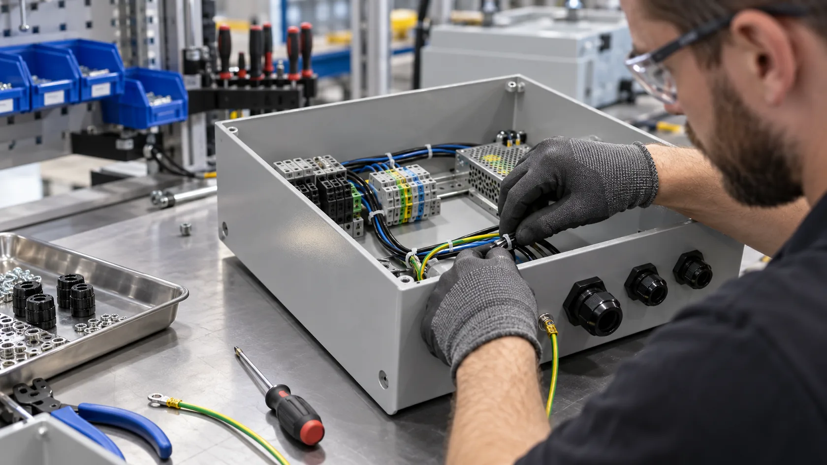
Cable entry is a mechanical, sealing, electrical, and assembly problem at the same time. A round hole is only the beginning: the selected gland or connector needs a compatible panel thickness, sealing surface, clamp or locknut clearance, cable range, torque access, and room for the cable to bend inside the enclosure.
Check every add-on in the finished state
UL Solutions notes that environmental-rated enclosure accessories are evaluated for concerns such as corrosion, UV degradation, gasket materials, and maintaining an environmental seal when mounted. That is a useful reminder to check windows, fans, plugs, handles, hinges, and cable fittings as part of the final assembly—not as unrelated purchase items.
For a metal housing, identify grounding and bonding points before cosmetic finish is applied. For any enclosure, confirm screwdriver access, insert installation order, display or label alignment, and whether a service technician can remove the lid without disturbing the wiring. These small details are where a pleasant design review becomes a reliable product.
Use a DFM Review Before the First Production Sample

A design-for-manufacturability review turns an enclosure selection into a buildable plan. It does not take product ownership away from the buyer. It gives the buyer and manufacturer one structured chance to expose conflicts before tooling, programming, purchasing, or finishing makes changes slow.
Send the inputs that let the factory make useful comments
Provide the controlled drawing and 3D model, plus PCB data or a mounting drawing, connector part numbers, cable information, target volume, material and finish preference, exposure description, and any required validation. Clearly flag the dimensions that locate, seal, mate, or affect appearance.
Use the review to confirm:
- The selected process fits today’s volume and expected design changes.
- The usable interior includes wiring, plugs, fasteners, lid, gasket, and service clearance.
- Functional datums and tolerances are identified.
- Materials, finish, grounding, sealing, and cable entries work together.
- First-article and final-assembly checks reflect the actual installation.
The best DFM feedback often sounds simple: move a feature, add a radius, define a datum, change the panel sequence, or reserve clearance for a tool. In my experience, resolving that simple issue on the drawing is much better than discovering it on finished parts.
Conclusion

The right electronic enclosure is not chosen by dimensions alone. Start with the product’s environment and installation, define the protection target as an installed assembly, then work through material, usable interior, thermal path, production route, tolerance relationships, and assembly details.
From the factory side, I get the best results when a buyer sends the enclosure drawing together with the PCB, connectors, cable plan, expected volume, exposure, and the interfaces that cannot move. That gives us a practical basis to check manufacturability before the first sample—and to choose a housing that protects the product without creating avoidable cost or rework.