Skip to content


On an enclosure drawing, “powder coat, 80 microns” can look like a simple note. On the production floor, that one number reaches into corrosion protection, door and cover fit, threaded features, gasket contact, grounding points, and final appearance. A high reading is not automatically a good reading.
For a general single-coat steel enclosure, 60–80 µm is often a sensible starting range when the selected powder supplier supports it. AkzoNobel’s Interpon technical data sheet, for example, lists 60–80 µm for its stated test conditions. The final requirement should still come from the exact powder product, the steel preparation, enclosure geometry, exposure, and acceptance method—not from a number copied from an unrelated cabinet.
In my experience, buyers get the best result when they define a controlled dry-film range and the surrounding process instead of asking a coater to make the finish “as thick as possible.”
That practical distinction starts with knowing exactly what the thickness number represents.
What Powder-Coating Thickness Actually Means

Dry film thickness is the finished coating
The useful number is normally the cured dry film thickness (DFT): the distance from the steel surface to the outside of the finished powder film. It is not the amount of loose powder sprayed, the oven temperature, or a visual impression of how smooth the finish looks.
For steel, a magnetic-induction gauge is commonly used on a cured non-magnetic coating. ASTM D7091 describes non-destructive thickness measurement of non-magnetic coatings on ferrous and non-ferrous metals; the probe and the substrate need to match the method. A reading taken on a simple flat panel is useful, but it is not a full substitute for measurements on the released enclosure.
Keep microns and mils unambiguous
One mil equals 25.4 µm. That makes 60–80 µm roughly 2.4–3.1 mils. I put both units on a cross-border RFQ when different teams use different conventions, because a unit mix-up is much harder to fix after a production batch has been coated.
| Term | What it should mean in an enclosure specification | Common mistake |
|---|---|---|
| DFT | Cured film thickness measured on the finished part | Treating a gun setting as a thickness requirement |
| Target range | The approved upper and lower limits for the named powder system | Naming only one nominal value |
| Significant surface | A defined visible or service-critical area that can reasonably be measured | Measuring only easy broad faces |
Once the measurement basis is clear, the range can be selected for the real enclosure rather than by habit.
Start With a Practical Target Range

Use 60–80 µm as a starting point, not a shortcut
Many ordinary single-coat powder systems for steel are controlled around 60–80 µm. Product data sheets and coating guides also commonly show broader ranges such as 50–100 µm or 60–120 µm, depending on the system and part. That context makes 60–80 µm a useful conversation opener for indoor or moderate-duty fabricated enclosures, not a universal acceptance criterion.
The proper target may change with powder chemistry, color, texture, part shape, intended appearance, corrosion system, or coating supplier’s validated application window. The named product’s technical data sheet should set the allowable film build and cure schedule. If a project requires multiple coats, a primer, or galvanized steel, specify each layer and the total system deliberately.
Start with service and geometry
| Enclosure situation | Sensible thickness discussion | What still needs confirmation |
|---|---|---|
| Indoor control enclosure | A single-coat range supported by the selected powder, often beginning near 60–80 µm | Fit features, contact points, chemical exposure, and appearance |
| General outdoor steel enclosure | Exterior-suitable powder system with a defined DFT range | Pretreatment, edges, drainage, UV, corrosion exposure, and validation |
| Coastal or polluted installation | System design before increasing film build | Steel condition, pretreatment, primer or duplex approach, joints, and test basis |
| Tight-tolerance cover or machined insert | Lowest approved range that still meets the service need, plus masking where required | Gap stack-up, threads, gasket land, and assembly method |
I prefer to approve a real formed sample before locking a narrow range. Flat coupons help control a line, but they do not reveal every recess, return flange, or interference point in a cabinet.
The gauge reading matters, but it cannot compensate for a weak foundation underneath the film.
Thickness Is Only One Part of Corrosion Protection
Pretreatment and cure decide whether the film can perform
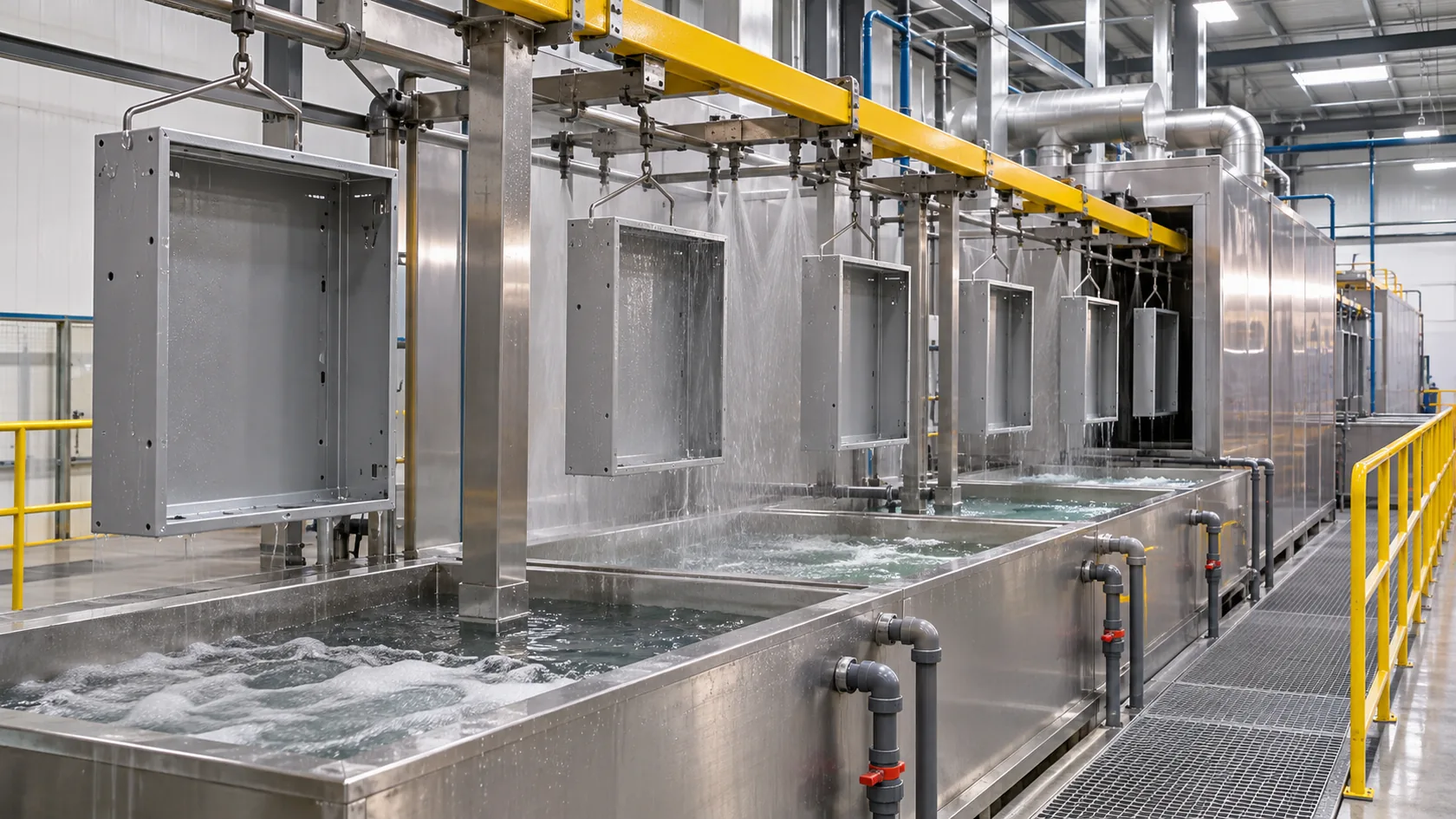
Oil, weld residue, oxide, salts, fingerprints, and early rust can weaken adhesion and create routes for corrosion beneath a seemingly generous coating. The steel must be cleaned and prepared with a conversion or other compatible pretreatment process appropriate to the material, powder, and service conditions. A thicker layer on contaminated steel is not a durable correction.
Cure is equally specific. The powder manufacturer’s cure schedule applies to the part temperature and time for that product, not merely to the oven display. A thin door, a heavy welded base, and a densely loaded rack can heat at different rates. Process control needs to show that the actual enclosure receives the approved cure.
Outdoor risk may change the system, not the number
For visible outdoor steel, an exterior-suitable chemistry is normally more important than adding an undefined amount of an indoor coating. The Powder Coating Institute notes that epoxies and epoxy-containing hybrids are generally poor choices when long-term exterior appearance is important, whereas suitable polyester and acrylic systems have better UV stability.
I have seen an impressive film-thickness report used to distract from unclear pretreatment or powder chemistry. For an outdoor cabinet, I would rather see a modest, controlled range on a compatible system than an inflated number with no evidence for the environment.
That system also has to reach the vulnerable features of the enclosure.
Geometry Changes the Coating You Can Achieve
Steel enclosures do not coat like flat panels
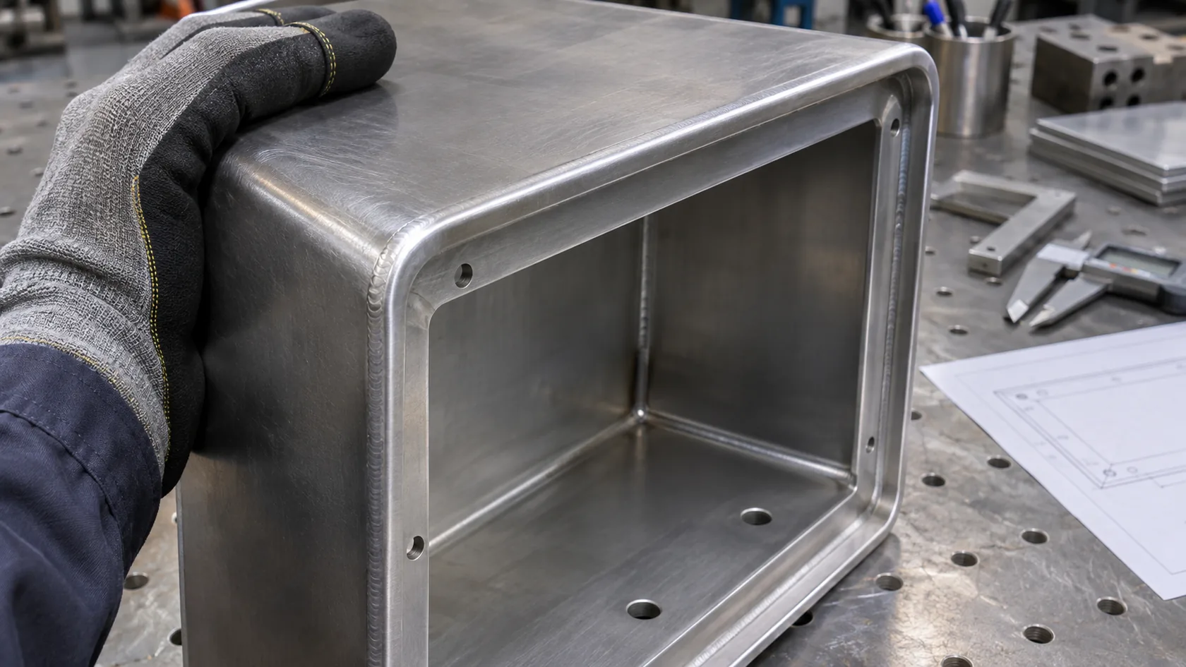
Sharp edges, burrs, rough welds, deep returns, narrow channels, screw lands, and closely spaced bends are harder to clean and coat evenly. Electrostatic powder is attracted to the grounded part, but the electric field can make deposition in deep recesses more difficult. The broad face may measure within range while a difficult feature receives less coverage.
Round or break sharp edges where the design allows, clean welds, remove burrs, and give the coating process access to critical faces. ISO 12944-3 focuses on design considerations that support corrosion protection, application, inspection, and maintenance. It is a useful reminder that coating quality begins in the drawing.
Tolerance stack-up needs the coating allowance
Powder coating adds thickness on every coated face. That matters on cover overlaps, sliding features, holes, threaded sections, gasket lands, press-fit features, and mating hardware. A blind assumption that “microns are too small to matter” can turn into a door rub or a fastener problem when both sides of an interface are coated.
| Feature | Risk if coating is ignored | Practical control |
|---|---|---|
| Cover-to-body gap | Binding, scratches, or an uneven visible gap | Reserve clearance for the approved maximum build on both mating faces |
| Threaded hole or stud | Lost thread engagement or difficult assembly | Mask, chase by an approved method, or use protected hardware design |
| Grounding/EMC land | Insulating film interrupts the intended contact path | Define a masked or engineered conductive interface and corrosion control |
| Gasket surface | Compression changes or sealing surface damage | Keep the land controlled; mask only where the gasket design requires it |
When a feature is critical, I want it shown on the drawing instead of leaving the coater to discover it after the first assembly trial.
The same discipline prevents a common mistake: treating extra powder as free protection.
Avoid the “Thicker Is Better” Trap

More film can create its own defects
Beyond the product’s intended application range, an excessively heavy film can affect appearance, flow, edge behavior, cure consistency, and the fit of mating parts. It may accumulate on exposed edges while recessed features remain difficult to cover. A high average reading therefore does not prove uniform protection where the enclosure is most vulnerable.
Thick film also changes manufacturing cost. It can increase powder use, rework, masking effort, rack time, and rejects at tolerance-sensitive interfaces. If protection is insufficient, the correct response may be better steel preparation, a suitable primer or coating system, improved edge treatment, drainage changes, or a justified test plan—not simply another pass through the booth.
Do not solve electrical or sealing needs by scraping paint later
Powder coating is typically electrically insulating. A protective-earth, bonding, or EMC path should use an intentional masked land or designed contact arrangement, with compatible corrosion protection around it. Randomly scraping a finished enclosure during assembly can expose steel and make the result hard to repeat.
Ingress protection is also a completed-system issue. Gasket compression, fasteners, cable glands, vents, connectors, mounting orientation, drainage, and installation workmanship influence water entry and condensation. I flag this early because coating thickness cannot turn a poorly designed joint into an IP-rated enclosure.
The practical response is to inspect the parts in the locations where these trade-offs actually occur.
Measure the Finished Part, Not Just a Flat Coupon

Agree where measurements count
Define the significant surfaces, the test locations, the number of readings, and the acceptance rule before mass production. Use locations that represent visible faces and accessible service-critical areas; avoid pretending that an impractical internal corner can be measured exactly like a broad panel. The selected method should account for the enclosure geometry, local curvature, and the gauge manufacturer’s instructions.
For coated steel, magnetic induction is typically appropriate. For non-magnetic conductive substrates such as aluminum, eddy-current measurement follows a different physical principle; ISO 2360 specifies an eddy-current method for non-conductive coatings on non-magnetic electrically conductive base metals. A supplier should calibrate and verify the instrument against known standards and the relevant substrate condition.
Build inspection into the first article
- Confirm the powder product, batch traceability where needed, color, gloss or texture, and approved cure basis.
- Inspect DFT at the agreed locations on a real enclosure, not only a convenient witness panel.
- Examine edges, welds, recesses, returns, masked areas, and assembly interfaces for coverage and fit.
- Record any approved repair method and require review before substituting a powder or pretreatment process.
My preferred first-article review includes the cover, hardware, gasket, and cable-entry parts assembled together. A coating can pass a gauge test and still reveal a clearance or contact problem only after assembly.
Those observations are most useful when the purchase order gives the factory a clear release target.
Write a Coating Requirement a Supplier Can Quote

Include the details that actually control the result
A useful powder-coating note identifies more than a color and one thickness. It should state the material and relevant fabrication condition, the installation environment, the approved powder family or product, pretreatment expectations, DFT range, measurement method and locations, cure basis, appearance requirement, and any masked or tolerance-critical areas.
Where corrosion testing is justified, name the test standard, sample or assembled configuration, exposure, duration, scribe condition when relevant, evaluation rule, and approval owner. ASTM B117 itself cautions that salt-spray results alone seldom correlate predictably with natural environments, so a bare “hours” requirement should not be treated as a field-life promise.
Example RFQ wording
> Steel enclosure: clean, deburr, and prepare using a pretreatment process compatible with the approved powder system. Apply the specified exterior-suitable polyester powder, RAL ____ / gloss ____, to a cured DFT of ____–____ µm on agreed significant surfaces, measured on finished steel parts by a calibrated magnetic-induction gauge. Protect or mask the identified grounding, threaded, gasket, and tight-fit features. Confirm cure controls and submit first-article DFT and appearance records before production release.
This is only a template: the values, powder chemistry, pretreatment, masking, and validation must match the project. In quotations, I ask buyers to tell us which faces are cosmetic, which are tolerance-critical, and what the cabinet will face after installation. That lets the coating requirement protect the product rather than create avoidable manufacturing ambiguity.
A well-written note turns a thickness number into a controlled production decision.
Conclusion

For many general steel enclosures, 60–80 µm is a reasonable place to begin the discussion. It is not a universal answer. The correct powder-coating thickness is the range approved for the exact powder system and then checked against exposure, pretreatment, cure, edges and recesses, clearances, grounding points, sealing features, and the way the enclosure will be installed.
After years of reviewing enclosure details, I trust a clear film range and a disciplined process far more than the biggest number on a gauge. If you are preparing a steel enclosure RFQ, send the drawing, service environment, finish target, and any tight-fit, grounding, or gasket areas. We can help identify where the coating specification needs detail before production starts.