Skip to content

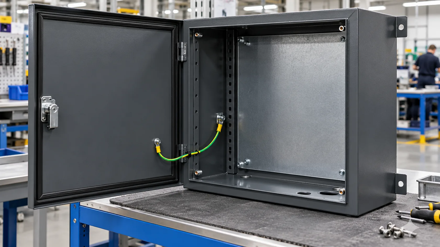
A powder-coated enclosure can look like one continuous piece of metal, especially after a clean black or gray finish has covered the panels, door, fasteners, and seams. The trouble starts when that same finish sits between a grounding lug and the chassis, or between a removable door and the body. The cabinet is metal underneath; the completed contact path may not be.
The short answer is that ordinary cured powder coating normally does **not** conduct electricity. It usually behaves as an insulating polymer film. That can be useful for corrosion protection and appearance, but it is a design issue wherever the finished enclosure needs a defined protective-earth bond, chassis connection, static-control route, or EMC interface.
There are exceptions. Some specialist powders are formulated to be conductive or static dissipative, but they are not interchangeable with a standard decorative powder coat. The product data, film thickness, substrate, measurement method, and installed assembly all matter.
In factory work, I treat the finish and the conductive path as two separate features that must meet at controlled interfaces. That small distinction prevents a lot of late rework. First, it helps to separate the coating process from the electrical behavior of the cured film.
The Short Answer: Standard Powder Coating Usually Does Not Conduct
The substrate conducts; the normal coating film does not
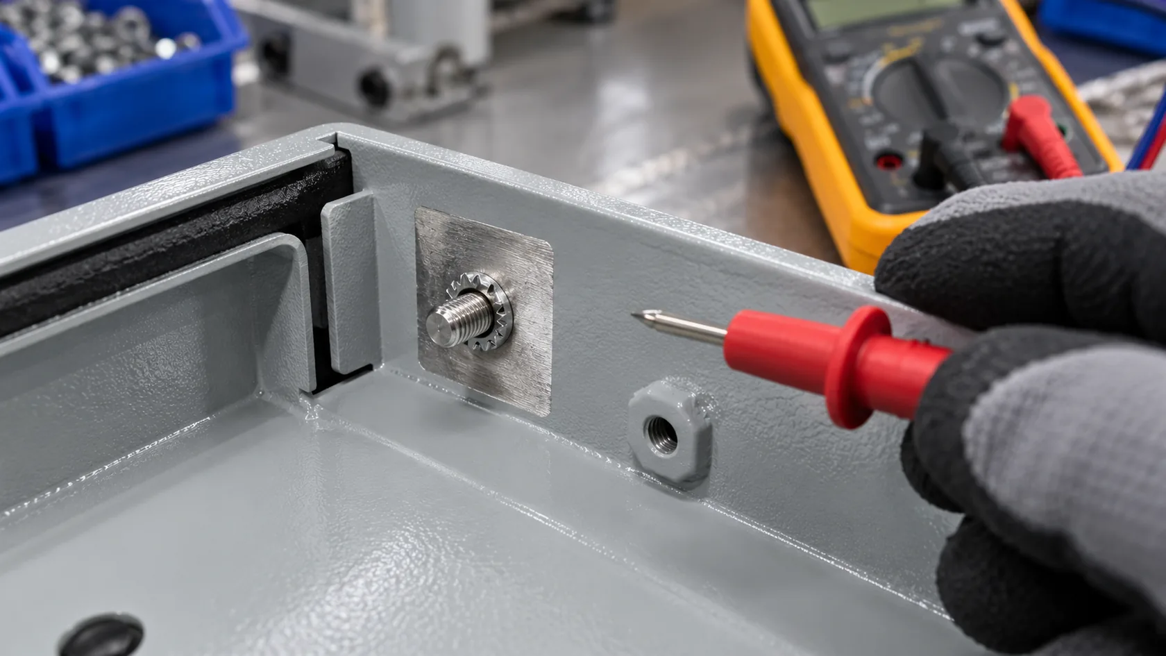
Steel and aluminum enclosure panels are conductive, but the usual polyester, epoxy, epoxy-polyester, or polyurethane powder film is polymer-based. Once it is cured into a continuous layer, it normally separates a terminal, washer, mating panel, or probe from the metal beneath it. A meter may find a path around a joint through an exposed edge, screw, or jumper, but that does not mean current is passing through the coating as a designed connection.
The electrical behavior is not just a theoretical detail. PPG notes that a powder coating can provide electrical insulation when it forms a continuous, uninterrupted film at sufficient thickness. Purpose-designed insulating powders are even used on electrical components, where their properties are measured rather than assumed.
Electrostatic application is not evidence of conductivity after cure
Powder is commonly charged during spraying so that it is attracted to a grounded metal workpiece. That process sometimes creates a misleading impression that the finished coating is conductive. The coating-line connection is temporary and belongs to the application process; the cured film can still be highly resistive.
Nordson's powder-system grounding guidance is a useful reminder that conductive equipment and workpieces require deliberate grounding during application. It does not turn a normal cured powder film into a protective-earth or EMC path in the delivered product.
From my perspective, the practical rule is simple: unless the specified powder supplier data says otherwise, design a standard powder-coated surface as nonconductive. That assumption is conservative, visible in a drawing review, and far safer than discovering an insulated lug at final assembly.
That default leads naturally to the next question: what makes the cured layer electrically different from the metal it protects?
Why a Cured Powder-Coat Film Usually Acts as an Insulator
The film is a polymer barrier, not bare metal
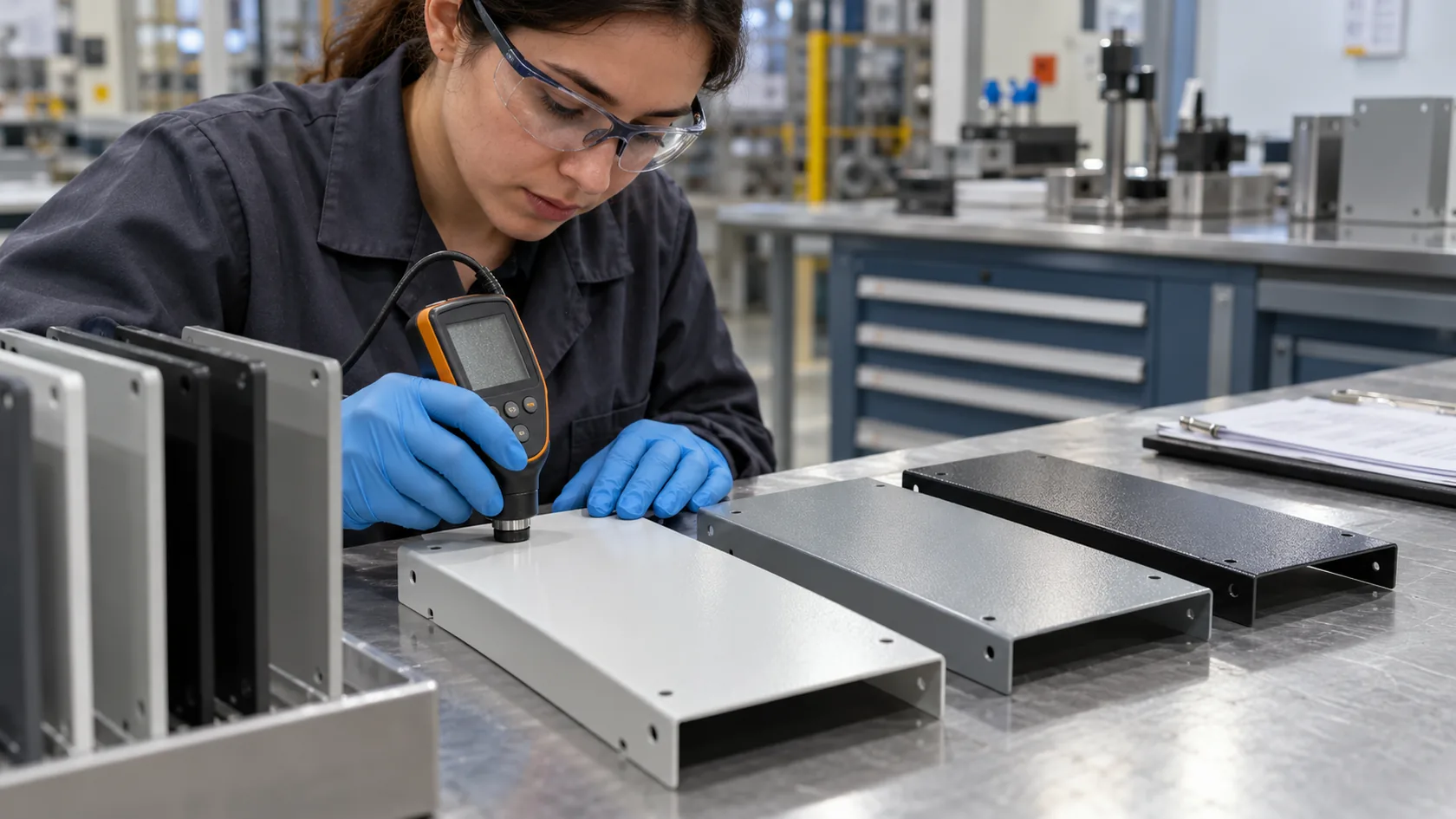
Powder coatings combine a resin system with pigments, additives, and sometimes fillers. During cure, the deposited powder flows and becomes a continuous film. In an ordinary finish, the formulation is intended to protect and decorate the metal, not to create a low-resistance route through it. Film continuity is exactly why standard powder coating can be helpful as an electrical barrier in appropriate applications.
Electrical-insulation products make the distinction clear. For example, an AkzoNobel epoxy powder designed for armature-slot insulation lists resistivity, tracking performance, and dielectric strength in its technical data. Those values belong to that named product under its stated methods and conditions—not to every powder coat on every enclosure.
Thickness, defects, moisture, and geometry still matter
No coating should be treated as an unlimited electrical safety barrier. Electrical behavior can vary with the exact formulation, applied thickness, cure, pinholes, damage, edges, humidity, contamination, and the geometry of the test. A scratch or sharp feature can expose the metal below; a damp, dirty surface can change leakage and tracking behavior; a joint can bypass the film through its hardware.
| Question | Why it matters |
|---|---|
| Which powder chemistry and product code? | A standard polyester and a specialist insulating epoxy may have very different intended use and data. |
| What film thickness and cure profile? | Film formation and thickness affect whether the coating is continuous and how it performs. |
| Is the concern insulation, static control, or a metal-to-metal bond? | These are different electrical functions with different acceptance methods. |
| What is the real environment? | Moisture, contamination, abrasion, UV, chemicals, and service access can change the practical result. |
I avoid promising a universal voltage or resistance value from a finish description alone. A generic phrase such as “black powder coat” tells me almost nothing about electrical performance. The relevant data sheet and the product-level test plan should carry that decision.
Once the coating is recognized as a barrier, the main enclosure risk becomes much easier to see: a required electrical interface may be buried beneath a very good finish.
Where Insulation Creates an Enclosure Risk
Protective-earth and bonding interfaces need intentional contact
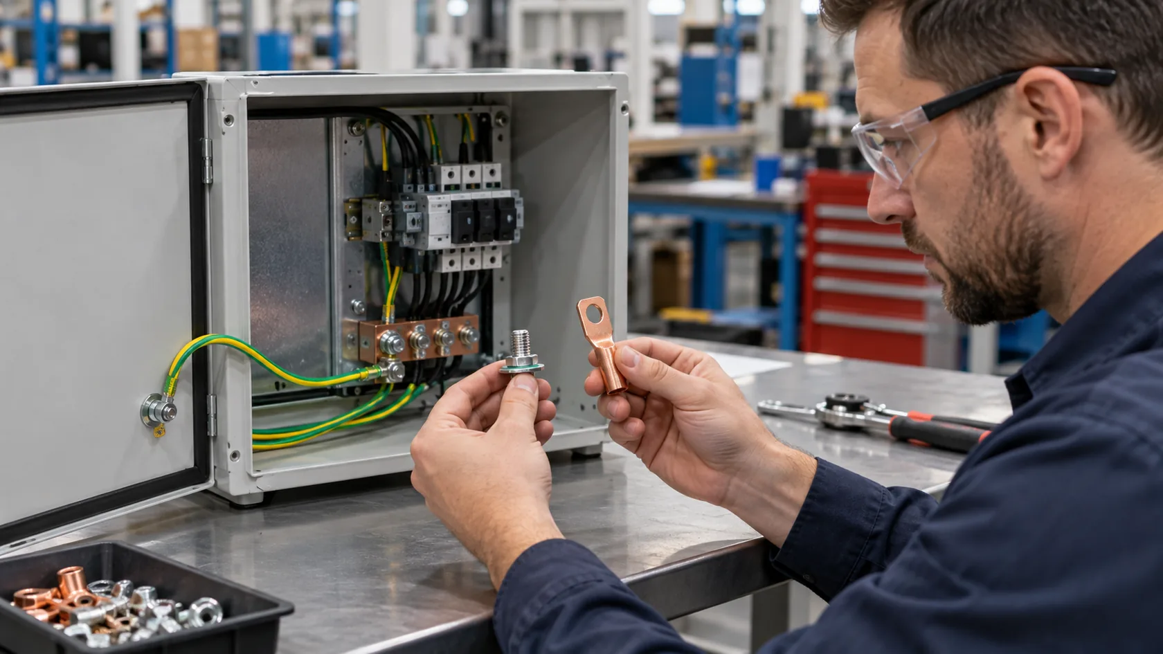
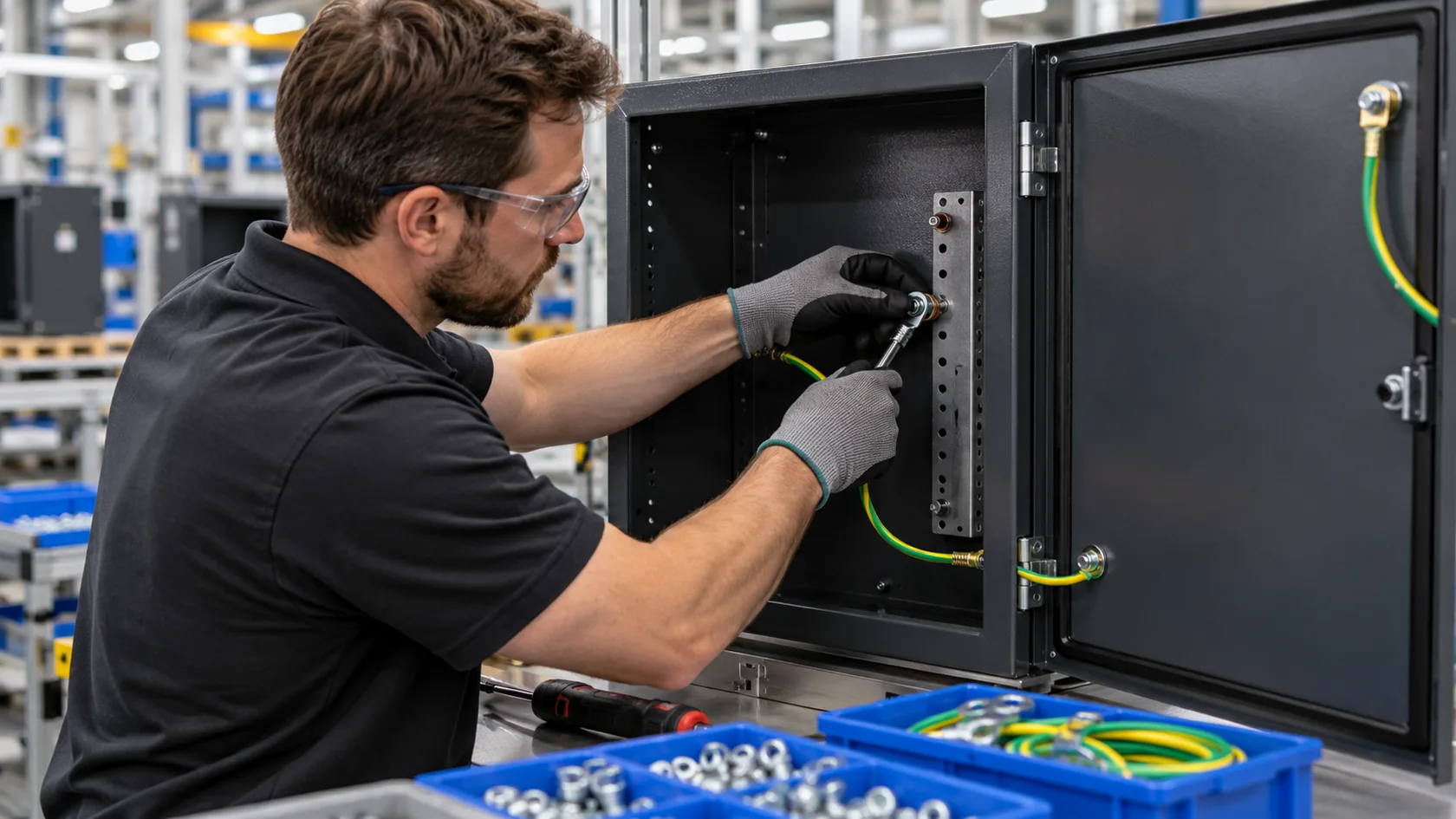
Where an electrical design requires a conductive chassis or protective-earth path, coating on threads, contact faces, and mating lands can interrupt it. OSHA's electrical rule says that nonconductive coatings at equipment grounding contact surfaces must be removed unless a fitting is designed to make removal unnecessary. The accountable product engineer and applicable standard determine the actual requirement, but the manufacturing lesson is clear: the intended contact cannot be left as an unspoken assembly assumption.
| Interface | Common failure after coating | Better manufacturing question |
|---|---|---|
| Earth stud or lug | Paint remains under a terminal or washer | Where is the defined contact land and what hardware meets it? |
| Door or removable cover | Hinge or painted fasteners are treated as the bond | Does the approved design require a dedicated jumper or controlled joint? |
| Internal panel | A coated subpanel is assumed to bond through screws | Which faces must mate, and can they be inspected after assembly? |
| Cable entry or connector shell | A gasket or finish isolates a designed chassis connection | Is it a protective, shield, or EMC function, and how is it assembled? |
A low-resistance DC path can be necessary for a product-defined protective bond, but it does not automatically demonstrate high-frequency shielding. At an EMC seam, geometry, seam length, contact pressure, gasket or spring-contact selection, cable-shield termination, and the actual frequency range can matter. Conversely, scraping a random patch of coating may harm corrosion resistance or sealing without solving an EMC problem.
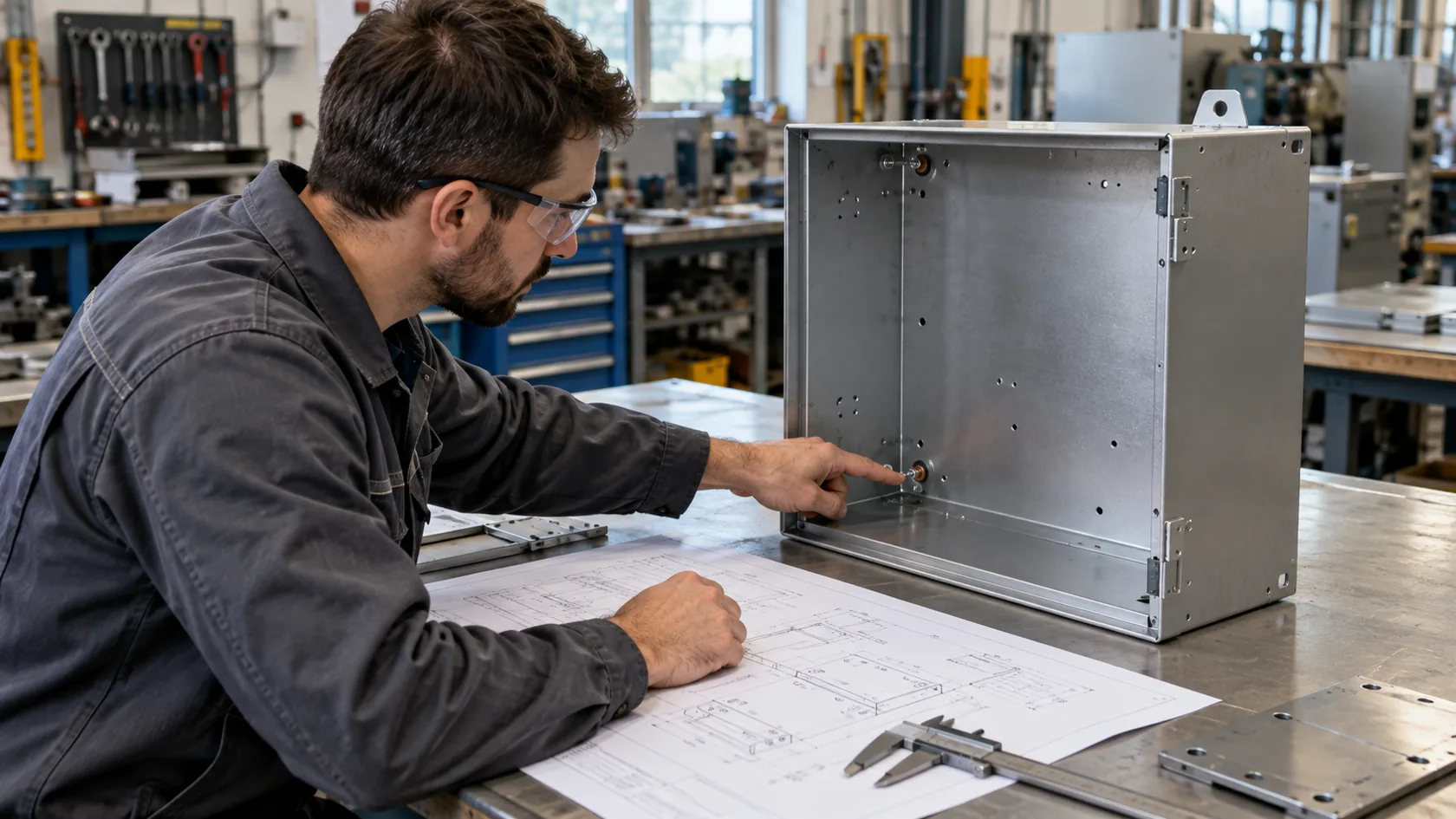
I have seen enclosure drawings where “ground here” was the only note beside a finished panel. That is not enough direction for the sheet-metal team, powder coater, and final assembler to produce the same interface repeatedly. A controlled contact land or a specified bond is much more reliable.
The exceptions deserve equal care: powders that genuinely conduct or control static have their own limits and should be specified by function, not guessed from appearance.
When Powder Coating Can Conduct or Dissipate Charge

Conductive and dissipative powders are specialist systems
Some powders include conductive additives or are formulated to dissipate static charge. They can be appropriate for defined ESD, process, or application needs. They are not the same as a normal decorative powder, and “conductive” and “dissipative” are not interchangeable terms. The required resistance range, measurement setup, thickness, substrate, humidity, and grounding arrangement need to be stated.
IGP's technical information on electrostatic-discharging powders, for example, discusses point-to-point resistance under DIN EN 61340-2-3 and cautions that the coated substrate affects the result. It also notes limitations with coated aluminum in ESD applications. This is a good example of why a finish name alone is not an engineering specification.
Request product data, not a verbal assurance
If a buyer needs a conductive or static-control finish, I would ask for the following before quoting it as part of an enclosure:
- The electrical function: static dissipation, a specified conductive surface, insulation, or another defined purpose.
- The named powder product, color/texture, supplier technical data, and allowed thickness range.
- The test method, probe arrangement, conditioning, acceptance range, and sample plan.
- The substrate and full assembly condition, including any masking, hardware, gaskets, fasteners, and earth route.
- The operating environment, cleaning method, wear exposure, and service life expectations.
Specialty powder can be a sensible solution when it matches a released design. I would not use it as a shortcut for a missing bond path. A known mechanical interface or jumper is usually easier to manufacture, inspect, and maintain than relying on a coating to carry a safety-critical function.
With the powder choice defined, the enclosure should be detailed so its intentional conductive points survive fabrication, coating, and service.
Design the Conductive Path Before Coating
Put required metal-to-metal interfaces on the drawing
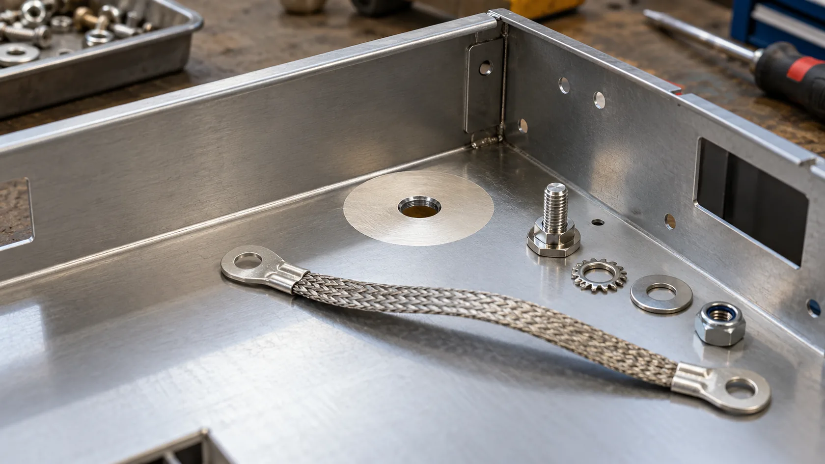
The cleanest approach is usually to identify each needed conductive interface before powder coating begins. Depending on the product design, that may be a masked contact land, a dedicated earth-stud area, an approved conductive treatment, specified contact hardware, or a flexible bonding jumper for a removable part. The feature needs to show its exact location, mating face, usable area, hardware stack, assembly order, and inspection access.
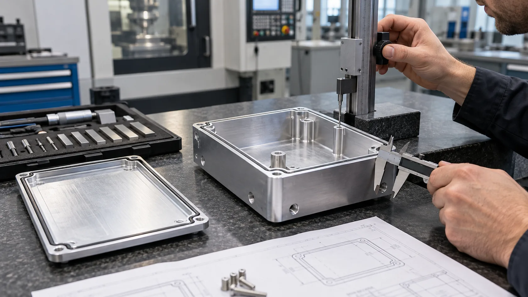
Masking is often more repeatable than an instruction to remove paint after cure. It allows the coater to preserve a defined area without creating uncontrolled scratches, burrs, debris, or damage to adjacent cosmetic surfaces. It also makes first-article inspection straightforward: the right metal is visible in the right place before final assembly.
Balance corrosion protection, sealing, and service access
An exposed contact area is not automatically a durable one. Base material, mating metals, moisture, salt, chemical exposure, drainage, torque retention, and maintenance access can affect the joint. A broad bare patch may make testing convenient but increase corrosion risk. A poorly positioned patch may interfere with a gasket or turn an ingress-rated enclosure into a leak path.
| Design choice | What to define with it |
|---|---|
| Masked land | Boundary, corrosion plan, handling protection, mating hardware, and visual inspection point |
| Ground stud | Base-metal contact, terminal stack, retention, access, and product-defined verification |
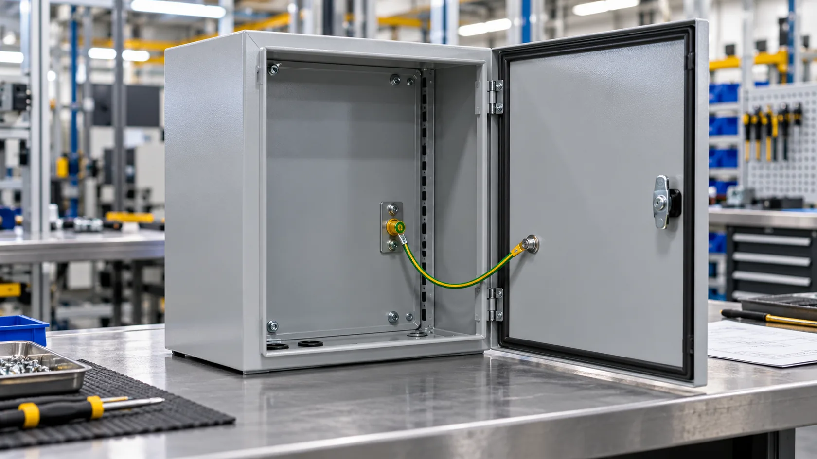
| Door jumper | Attachment lands, length through full travel, bend relief, abrasion protection, and service sequence |
| EMC interface | Surface preparation, seam geometry, gasket/contact design, cable termination, and validation basis |
I prefer a small, accessible, documented contact interface over a large unprotected bare area. It respects the purpose of the powder coat while making the electrical path an intentional part of the manufacturing package.
The final discipline is to verify the complete configuration rather than checking only an uncoated panel or an isolated component.
Specify and Verify the Finished Assembly
Make the supplier conversation specific
Before release, give the enclosure fabricator and powder supplier more than a color and gloss callout. Identify the powder product or approved equivalent, substrate, pretreatment, target finish, required masking, contact interfaces, cure constraints, and acceptance evidence. If electrical behavior matters, add the correct property, test method, conditioning, and accountable approval route rather than adding an undefined word such as “conductive.”
This is especially important after a change. A different powder supplier, texture, cure window, masking fixture, fastener, door hinge, or gasket can alter the physical contact stack even when the enclosure still looks identical.
Test the representative assembled product
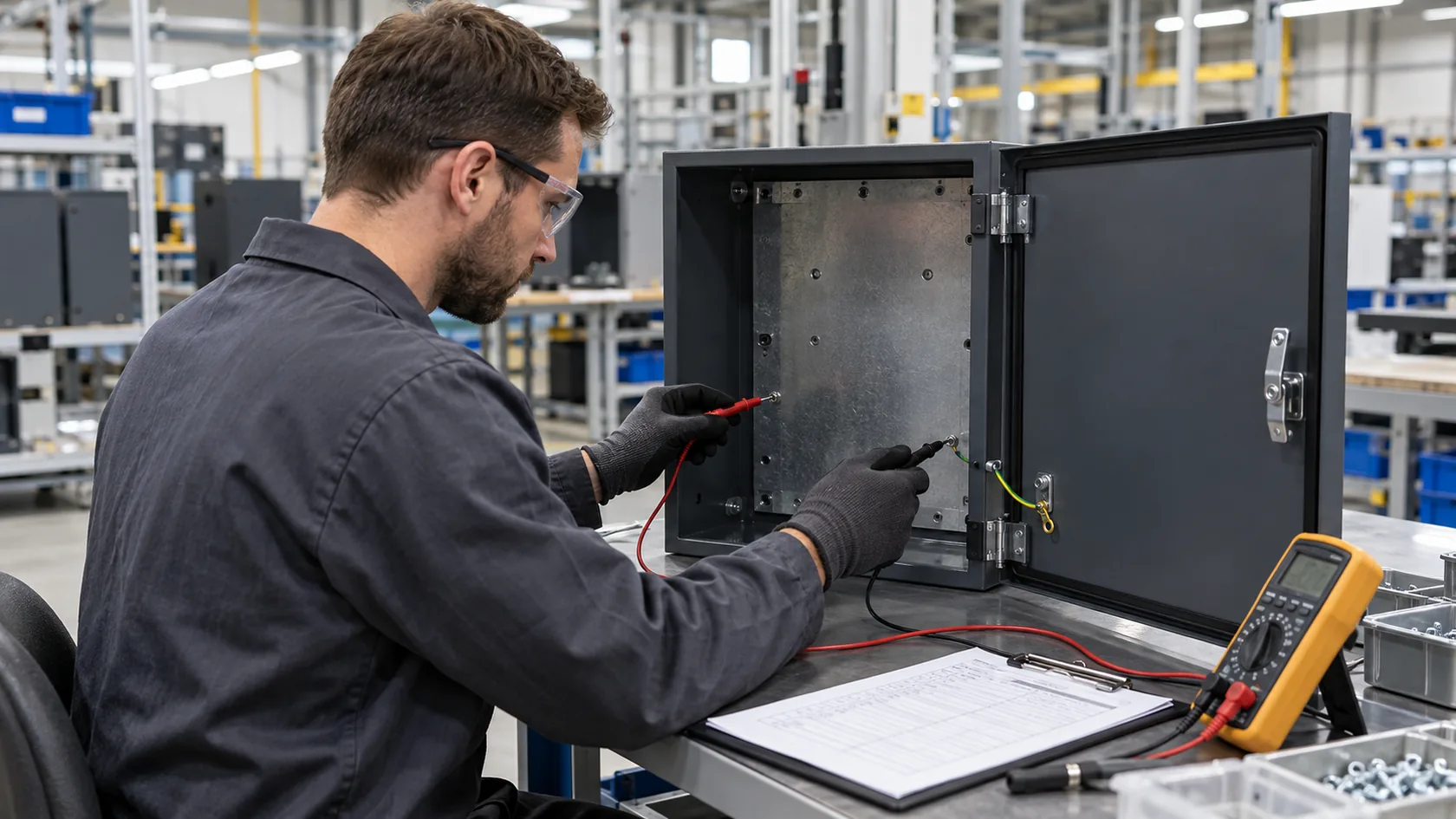
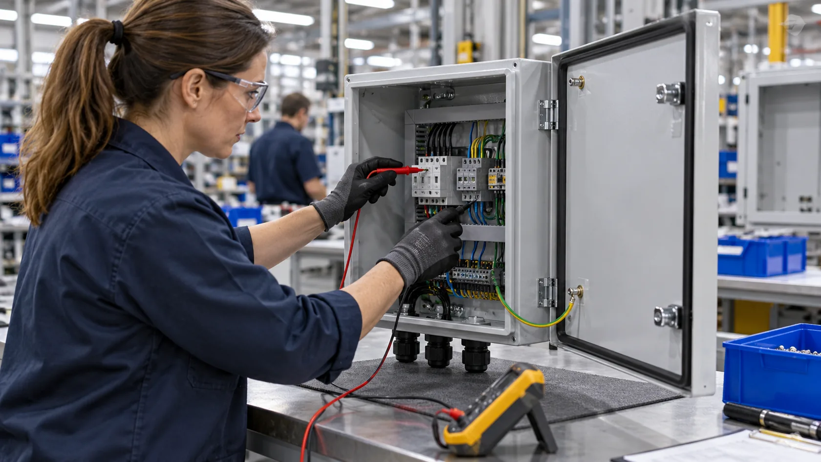
The suitable verification is determined by the product’s electrical and compliance requirements. That may include a visual inspection, a specified protective-bond or continuity test, an ESD resistance measurement, or an EMC validation plan. The test must reflect the finished condition: coating in place, final hardware fitted, panels closed, door jumper installed, cable entry assembled, and any relevant environmental or conditioning state applied.
I would not convert a convenient multimeter beep into a universal pass criterion. Probe locations, instrument, current, duration, acceptance limit, sampling, and design responsibility come from the applicable product standard and validated test plan. A clear drawing, a first-article record, and a controlled change review are more useful than a number copied from an unrelated enclosure.
That level of evidence lets the finish perform its protective job without hiding an electrical decision that the finished product still needs to make.
Conclusion
Standard powder coating normally does not conduct electricity. It is generally an insulating finish over a conductive metal substrate, which is exactly why it can disrupt a required ground, bond, or chassis interface if that interface is not designed before coating. Conductive and static-dissipative powders exist, but they need named materials, controlled application, and a function-specific test basis.
After years of working through enclosure details, I find the most dependable approach is modest and visible: keep the protective finish where it belongs, show every required conductive interface on the drawing, protect that joint for its environment, and verify the representative assembled unit. If you are releasing a powder-coated enclosure, send the drawing, intended electrical function, finish callout, environment, and cable-entry or door details. We can review the contact plan before the coating stage makes a small omission expensive.