Skip to content


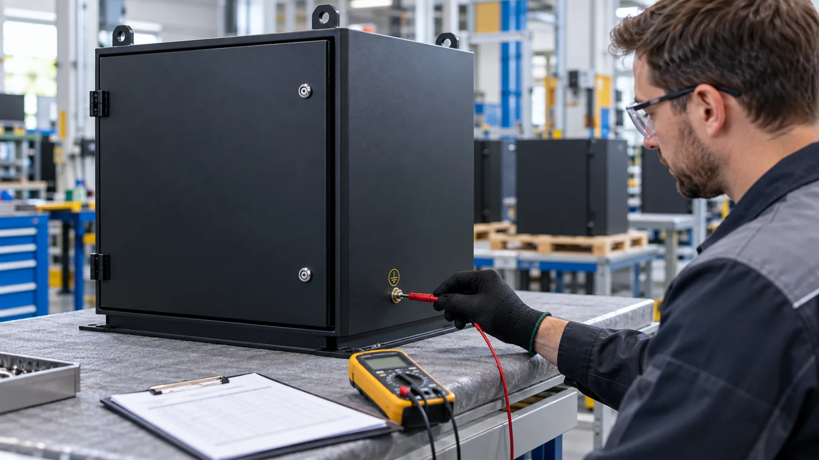
The awkward moment usually comes at final inspection. The powder coat looks even, the enclosure door closes well, and the earth symbol is in the right place. Then the test lead touches the terminal and the technician has to decide what, exactly, this check is meant to prove.
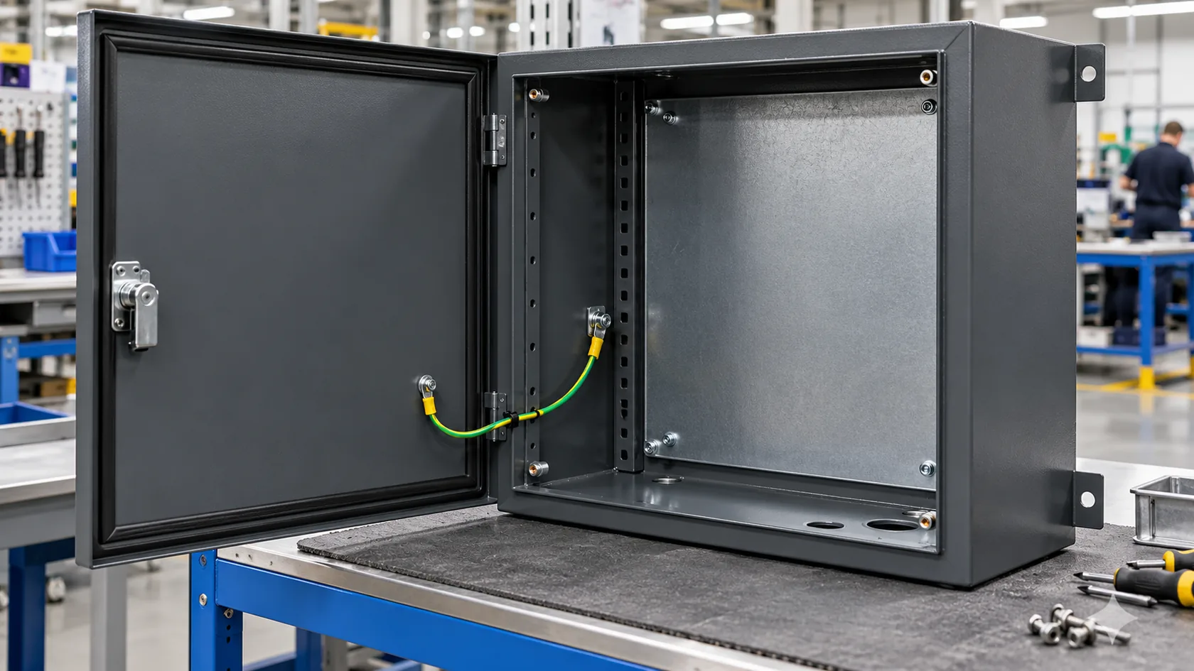
Powder coating protects and finishes metal, but it is normally an insulating layer. A continuity check is therefore not a ritual of touching two probes to any exposed screws. It is a controlled check of a path that the approved design says must remain conductive after fabrication, coating, and assembly.
For a custom enclosure, I treat the test as an enclosure-side control. The responsible electrical designer and compliance team must define the applicable product standard, test method, acceptance limit, fault-current duty, and sampling plan. My job is to make the relevant physical interfaces repeatable enough to inspect and measure. OSHA likewise describes the grounding path as permanent and continuous, which is a useful reminder that a ground symbol or a green-yellow wire alone is not the finished path.
The sensible starting point is to decide which continuity question is actually being asked.
Define What the Test Must Prove

Separate protective-earth, chassis, and EMC questions
One enclosure can have several conductive relationships: a protective-earth terminal to chassis, a removable door to chassis, an internal mounting plate, a cable-shield connection, and a high-frequency seam. They are not automatically the same test. A low-resistance result at a protective-earth point may be important for the intended safety path, yet it does not by itself establish RF shielding or finished-product EMC performance.
Start with the released drawing, wiring documentation, and assembly instruction. Mark the exact start and end points for every required path. Then identify the intended route: direct metal contact, a dedicated strap, a fastener stack, a connector shell, or another approved interface. The OSHA grounding-path guidance is clear that paths to ground must be permanent and continuous; it does not turn every metal-to-metal contact into a qualified path.
| Question | Typical test relationship | What the record must identify |
|---|---|---|
| Protective-earth path | Defined PE terminal to required conductive enclosure part | Terminal, route, assembly state, specified method |
| Removable-part bond | Chassis to door, lid, or cover where required | Strap or approved contact points, full installed condition |
| Internal chassis bond | Chassis to subpanel or conductive component | Hardware stack, finish boundary, drawing revision |
| EMC-related interface | Defined seam or shield termination | Applicable EMC validation plan, not only a DC reading |
I have seen teams lose time because “check ground” was the entire instruction. A short bond map is cheaper than having a technician infer electrical intent from a finished cabinet.
With the purpose fixed, the next discipline is to test the same physical condition that will leave the factory.
Make the Assembly Safe and Representative
Isolate, inspect, and establish the test condition
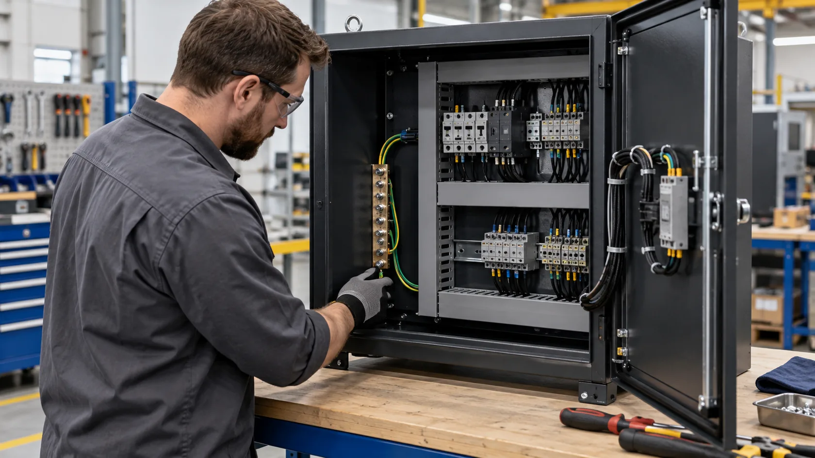
Only trained personnel following the site and product safety procedure should perform electrical testing. De-energize and isolate the assembly as required, verify the safe condition under the approved procedure, and avoid treating this enclosure guidance as a substitute for a qualified electrical test plan. The UK HSE guidance on electrical testing is a useful general reference for planning safe test work.
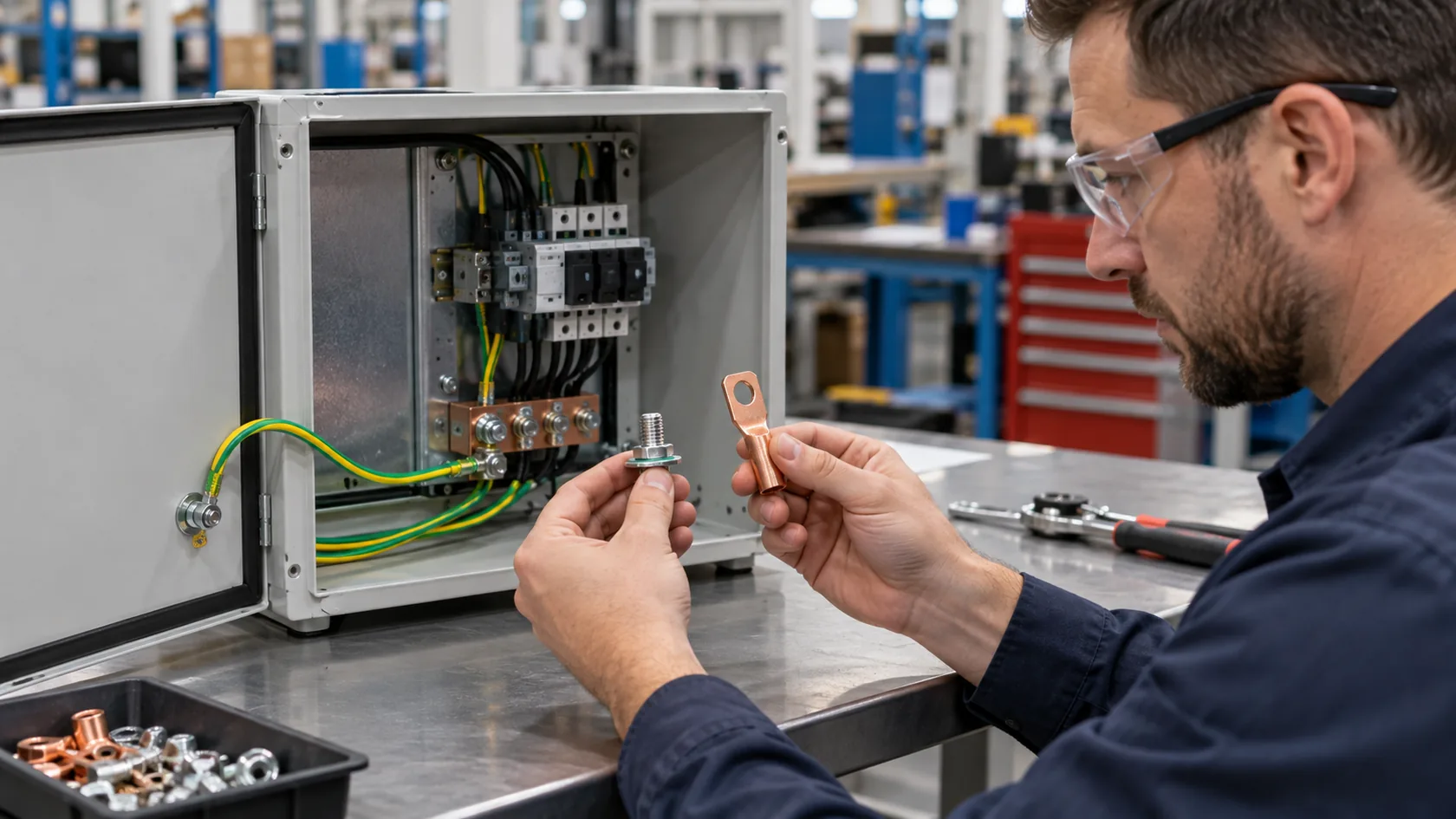
Before measuring, inspect the joint that is supposed to conduct. Look for coating across the specified land, oxide, cleaning residue, an incorrect washer sequence, loose hardware, a damaged strap, or a gasket pushed into the contact area. A meter can tell you that a path exists under that moment’s conditions; visual inspection explains whether it is the intended path and whether it is likely to remain reliable.
Test the representative released configuration. That means the intended door, cover, hardware, straps, cable entries, and mounting parts are installed as the product procedure requires. If a cover has to be removed for access, record whether the measurement represents the installed condition or only a subassembly. I prefer to settle this at first article, because a beautiful enclosure can hide a very different electrical stack-up after final assembly.
That preparation prevents a neat but irrelevant measurement.
Choose a Method That Matches the Requirement

Use an indicator for screening and a specified low-resistance method for acceptance
A continuity-beep mode on a handheld meter is convenient for a quick assembly screen. It can flag an obvious open circuit and help a technician trace whether a door strap is connected. It should not be silently promoted into an acceptance method if the applicable product requirements call for a defined low-resistance or protective-bond measurement.
The OSHA continuity-test overview makes the simple point that a continuity test verifies an equipment grounding conductor is electrically continuous. For an enclosure release record, the product team still needs to name the instrument, measurement arrangement, lead handling, any required current, allowed value, and sampling frequency. Those details depend on the product, installation, applicable standard, and intended fault path.
For low values, lead and contact resistance can dominate the displayed result. A suitable product-specified method may require lead compensation or a four-wire arrangement so the reading reflects the tested joint rather than the test leads. NIST’s discussion of four-lead measurement illustrates why separating current and voltage connections improves confidence in low-resistance work, even though it is not an enclosure acceptance procedure.
I would never insert a universal resistance number into a quotation or a blog post. A number without its test points, instrument, current, assembly condition, and governing requirement is only a number.
Once the method is chosen, probe placement decides whether the result answers the intended question.
Place Probes on the Actual Bonding Path

Test from the defined terminal to each required interface
Place one probe at the defined source point, commonly the specified protective-earth terminal or chassis point. Place the other probe on the defined finished interface: the door-side bond land, subpanel, cover, cable-entry metalwork, or other point named on the bond map. Avoid an easy nearby screw unless that screw is itself the approved interface.
Use clean, repeatable probe contact. Do not pierce surrounding cosmetic powder coat simply to obtain a reading. That may create corrosion damage and prove a path the released design never intended. If the procedure needs an exposed location, put it on the drawing or test fixture plan so every operator uses the same spot.
For each point, capture enough information to repeat the result:
- Assembly or serial reference, drawing revision, and tester identification.
- Defined probe locations and whether the enclosure is fully assembled.
- The specified measurement method and the observed result.
- Any lead check, compensation step, or fixture confirmation required by the approved procedure.
- The reviewer, date, and disposition when a result is outside the defined requirement.
On a powder-coated assembly, I favour a named probe-point photo in the work instruction. It prevents a good technician from becoming the only person who knows where the paint is intentionally absent.
The next risk is subtler: a reading can pass through an unintended route.
Investigate a Pass That Does Not Make Sense
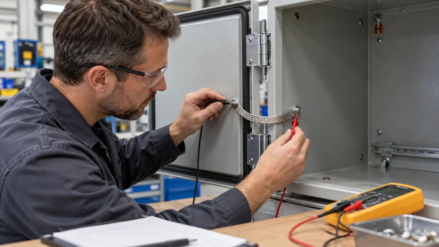
An unexpected low reading may travel through a temporary clamp, test fixture, mounting rail, cable shield, hinge, or another installed part instead of the intended bond. A door can appear continuous through a hinge during one check and become unreliable after lubrication, coating wear, corrosion, or a replacement hinge. If the design requires a door bond, verify the dedicated strap or approved contact route, not just the most convenient metal path.
When a result conflicts with the drawing or an inspection, pause and investigate. Remove or isolate parallel paths only when the approved procedure permits it, then repeat the product-defined test. Do not improvise by grinding away paint around the test point. Occupational electrical guidance has long recognized that nonconductive coatings at required contact surfaces have to be deliberately addressed; the answer is a defined contact design or fitting, not a last-minute scratch.
The same caution applies to corrosion protection. UL’s protective-coatings information describes powder and other organic coatings as corrosion protection for outdoor electrical enclosures. That protective role remains valuable. The design should reserve only the necessary conductive lands and specify how their exposure, mating hardware, and inspection will survive the environment.
From the factory side, a suspicious pass concerns me as much as a clean failure. A failed test tells us where to look; a result obtained through an accidental parallel path can escape into production unnoticed.
Once the path is credible, make the result useful after the enclosure leaves the inspection bench.
Record the Result as Production Evidence

Link the result to the drawing, assembly state, and change control
A continuity result is most useful when another qualified person can reproduce and interpret it later. Keep the evidence tied to the drawing revision, finish specification, test-point definition, assembly instruction, instrument or fixture, and the actual configuration tested. A photograph can support the record, but it should not replace the measurement context.
Use a release record that answers these questions:
- Which exact conductive relationship was tested, and why is it required?
- Was the enclosure in the final intended assembly state?
- Which approved test method and acceptance criterion applied?
- Were the defined lands, hardware stack, straps, and retention features visually acceptable?
- Did any change to coating, masking, fasteners, door hardware, cable entry, gasket, or mounting require review?
Escalate changes that affect RF seams, conductive gaskets, cable-shield termination, sealing, or field installation. A DC continuity measurement is not evidence that the finished apparatus meets every safety or EMC obligation. It is one controlled piece of evidence for the specific path it was designed to check.
That record lets a powder-coated finish stay both protective and electrically intentional.
Conclusion
Checking continuity in a powder-coated enclosure begins before the probes touch metal. Define the required path, use the released and safely isolated assembly, apply the product-specified method at fixed probe points, rule out accidental parallel routes, and preserve a repeatable record. The coating is not the enemy; an unspecified interface is.
After years of reviewing custom enclosure details, I trust a check most when the drawing, finish mask, hardware stack, and test record all describe the same joint. If you are releasing a new powder-coated enclosure, send the relevant drawing, finish specification, intended grounding or bonding function, service environment, and product test basis. We can review the contact interfaces before production makes a hidden path hard to verify.