Skip to content

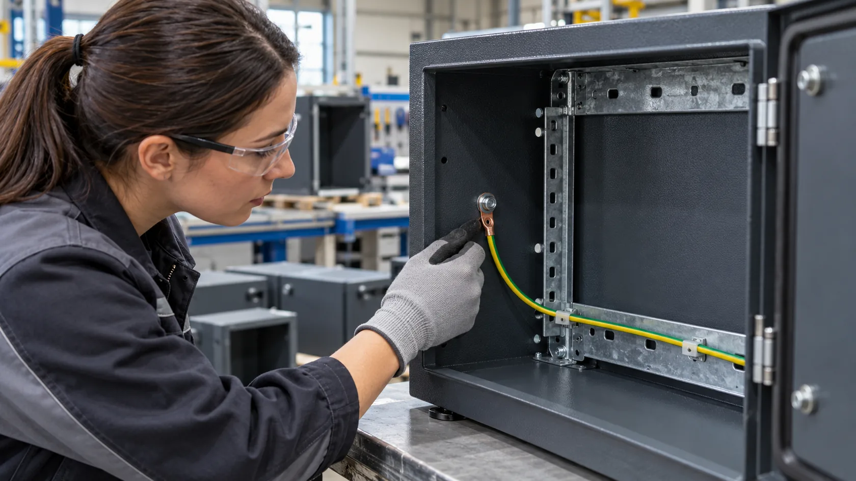
A powder-coated enclosure can leave a factory with a neat finish, a dedicated earth stud, and a good first inspection. Months later, it may be opened for a wiring change, moved into a wetter location, or have a door refitted. That is when electrical continuity can quietly become a maintenance issue rather than a drawing issue.
Powder coating can be a sensible finish for a custom steel or aluminum enclosure because it helps protect exposed surfaces and gives a consistent appearance. It is also normally nonconductive. Any joint that must remain electrically continuous therefore needs to be designed, assembled, protected, and maintained as an intentional interface. A metal cabinet is not automatically a continuous electrical assembly just because its underlying panels are metal.
For this article, I am discussing the enclosure-side controls that help preserve a product-defined protective-earth or bonding path. The responsible electrical and compliance teams still need to define the applicable product, installation, fault-current, and verification requirements. OSHA's explanation of a permanent, continuous grounding path is a useful reminder that the finished path matters, not merely the presence of a green-yellow wire or a ground symbol.
In my experience, the difficult failures are rarely dramatic. They are often a painted-over contact land, a loose strap after service, or corrosion under a reassembled fastener. The practical solution is to make the path inspectable from the first drawing through every service event.
That begins by identifying exactly which interfaces are meant to stay conductive and why.
Identify the Continuity Path Before Maintenance Starts

Map each required conductive interface
“Maintain continuity” can refer to several different jobs. A chassis protective-earth point, a removable door bond, a mounting-panel connection, a connector-shell interface, and an RF seam may all be present in one enclosure. They may need different hardware, surface conditions, and evidence. Treating them as one generic grounding note creates an easy way to miss an interface during repair.
| Enclosure interface | Possible required function | Maintenance question |
|---|---|---|
| Chassis PE point | Product-defined protective connection | Does the specified lug and hardware still reach a prepared chassis surface? |
| Door or removable cover | Bonding of a separate conductive part | Can opening, removal, or a hinge change interrupt the defined path? |
| Internal panel or subplate | Defined chassis relationship | Has repainting, replacement, or a new fastener stack changed the contact? |
| Cable-entry or connector shell | Product-defined shield or chassis interface | Did a gasket, paint boundary, or replacement connector change the designed interface? |
UL's discussion of metallic enclosures makes the same basic distinction: parts that must serve an equipment-grounding function have to be bonded where necessary to preserve continuity and carry the current the design anticipates. That does not mean every screw needs bare metal. It means the required path needs a known route and a known joint.
I normally ask for a small interface map before a service program begins. It lists the two parts, their intended function, the permitted surface condition, the approved hardware, and the inspection evidence. It saves technicians from interpreting a cosmetic scratch, a spare hole, or a hinge as an electrical feature.
Once the path is visible on paper, each serviceable joint can be made reliable in the real enclosure rather than only in a CAD model.
Design Contact Points That Survive Service
Make the controlled joint visible and accessible
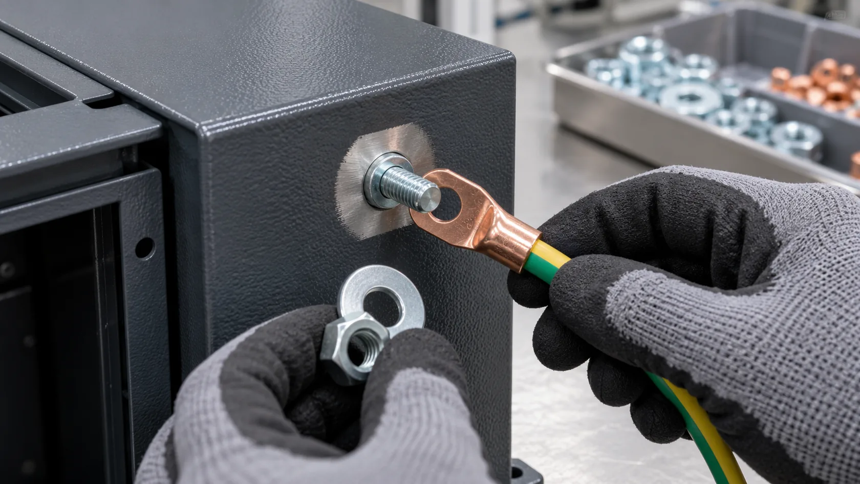
A contact point works best when it is a deliberately bounded feature: a masked contact land, an approved conductive surface treatment, or another specified condition that matches the equipment design. The land needs to fit the actual terminal, washer, strap, or mating surface—not an idealized component in a drawing. It also needs tool clearance and a location that can be inspected after the enclosure is wired.
| Approach | Useful when | Control that should be defined |
|---|---|---|
| Masked contact land | An accessible chassis stud or repeatable bolted connection | Boundary, handling protection, visual inspection, and corrosion plan |
| Approved conductive treatment | A material-specific interface needing corrosion management | Compatibility with substrate, environment, and electrical requirement |
| Controlled post-finish operation | A reachable feature with a validated, clean process | Burr/debris removal, exposed-edge protection, and documented inspection |
| Design-approved contact hardware | Only where the joint was designed and validated for it | Surface condition, stack, retention, torque or other specified assembly control |
Sandia's electrical-bonding guidance is written for a different class of equipment, but its practical point transfers well: mating surfaces should be free of nonconductive contaminants such as paint, oils, and inks where direct electrical contact is required. It is not a license for a technician to abrade any finished surface. The drawing should state where preparation is allowed and how the finished joint is protected.
I prefer a clearly marked contact land to an instruction saying “remove paint if needed.” The first approach can be quoted, masked, photographed, and checked; the second turns a controlled assembly feature into an operator judgment call. On a serviceable enclosure, that difference shows up every time a lug is removed.
The prepared surface is only half of the issue, though. A joint that conducts on day one can deteriorate if its corrosion boundary is left undefined.
Control Corrosion Without Re-Insulating the Joint

Treat corrosion protection and continuity as one interface decision
An exposed contact land exists because the joint needs conductivity, but bare metal can bring an environmental risk. Condensation, salt, cleaning fluid, residue from a process area, and a trapped washer interface can change the surface over time. The right response depends on the base material, the joint geometry, the real exposure, the mating metal, access for inspection, and the product’s approved requirements.
NASA's Electrical Bonding Design Guide notes that bond performance depends on surface condition, cleanliness, contact pressure, and the environment. Its aerospace context is not a generic enclosure specification, yet it is a useful warning against treating a serrated washer or an exposed patch as a complete corrosion strategy.
For an outdoor or washdown application, I would review these practical points with the product team:
- Is the contact location shielded from standing water and routine spray, or is drainage required around the joint?
- Are the base metal, fastener, lug, and any treatment compatible for the service environment?
- Can the contact land be reached without damaging surrounding coating or a gasket during inspection?
- Does a coating repair, sealant, or barrier material belong near the joint, and could it unintentionally insulate the intended path?
- What service interval or event should trigger a visual and product-specified electrical check?
It is tempting to protect every visible metal edge with the same coating system. I would keep the contact interface separate from that cosmetic instinct. A small, controlled area with an agreed protective plan is usually safer than a broad bare patch or a buried joint that cannot be checked.
Environmental control also needs to survive movement. Doors, covers, and removable panels deserve their own continuity plan.
Maintain Doors, Covers, and Other Moving Parts

Do not treat hinges as the entire continuity plan
A door may look electrically connected through its hinges or painted fasteners until lubrication, wear, coating, corrosion, vibration, or a replacement part changes the contact. If the approved product design requires the door or cover to be bonded, show that path directly. A flexible bonding strap can be suitable when it has the correct routing, attachment points, bend allowance, mechanical protection, and service movement for the application.
Schneider Electric's enclosure-layout guidance separates broad conductive contact for EMC purposes from ordinary cabinet construction, and it calls out deliberate grounding of the enclosure, door, and subplates in the relevant installation. This is why I keep protective bonding and high-frequency shielding as separate design questions even when they share an enclosure.
For a moving part, I check the practical failure modes before shipment and again after a maintenance change:
- Open the door or remove the cover through its real service travel; the strap must not pull, pinch, rub through, or catch on cable bundles.
- Confirm the attachment hardware and prepared lands remain visible enough to inspect.
- Reinstall the part in the documented sequence; a strap tucked behind a gasket or a lug trapped under a painted washer is not a controlled result.
- Review whether a replacement hinge, panel thickness change, or added component has altered the intended path.
From the factory side, I am cautious about relying on a hinge alone. It may be an acceptable part of a validated design, but a maintenance team should not need to guess whether a lubricated, painted, or replaced hinge is still carrying the product’s required bond.
The same discipline applies after any intervention. A completed service job should close the continuity loop instead of merely closing the door.
Recheck After Service, Modification, or Process Change

Verify the representative assembled condition
Continuity is easiest to lose when a change seems unrelated: a new powder supplier, a revised masking fixture, a replacement door, a different fastener lot, a connector change, or a field repair. Each can change the physical contact stack. A documented change review helps decide whether the original inspection still applies or whether the product needs a new representative check.
Nordson distinguishes protective-earth grounding from electrostatic/ESD grounding in its powder-system guidance and explains why frequency and conductor geometry can matter. That is a useful caution for enclosure maintenance: a convenient DC reading at one stud does not prove RF seam behavior, shielding performance, or full compliance of the finished apparatus.
Before releasing a serviced or changed enclosure, I would use a short, product-specific checklist:
- Verify that every required contact land, strap, terminal, or interface is present at the specified location.
- Inspect for paint, oxide, cleaning residue, loose debris, damaged coating boundaries, and corrosion at the defined contacts.
- Confirm the approved hardware stack, retention method, cable/strap routing, and access condition.
- Run the electrical or continuity check specified by the responsible product and compliance team on the assembled configuration.
- Escalate changes that affect EMC seams, cable-shield termination, gasketing, or environmental sealing to the appropriate validation plan.
I would not issue a universal resistance limit in a general enclosure article. Probe points, instrument, current or measurement method, acceptance criteria, and sampling plan come from the applicable product requirements. Good production evidence is a clear record of the interface, the assembly state, and the specified result—not a meter screenshot detached from the design intent.
With that record, a powder-coated finish remains an asset to the product rather than a hidden source of continuity risk.
Conclusion
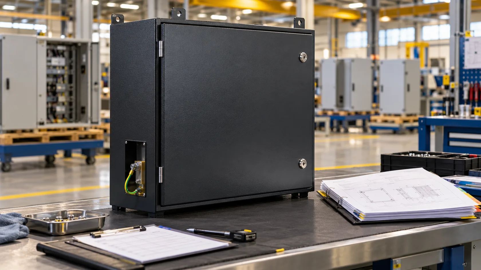
Maintaining electrical continuity in a powder-coated enclosure is not about stripping coating from every joint. It is about preserving only the interfaces that the approved product design needs to keep conductive, then protecting and inspecting them through service life. Map the path, define repeatable contact points, control corrosion, give moving parts a deliberate bond, and recheck after a meaningful change.
After years of handling custom enclosure details, I find the best continuity plan is one a technician can follow without interpretation: the drawing shows the contact land, the assembly record shows the hardware and route, and the maintenance process tells the team what must be rechecked. If you are preparing a new enclosure or a service modification, send the enclosure drawing, finish specification, cable-entry layout, expected environment, and product test basis. We can review the contact interfaces before a tidy powder coat hides an important electrical decision.