Skip to content
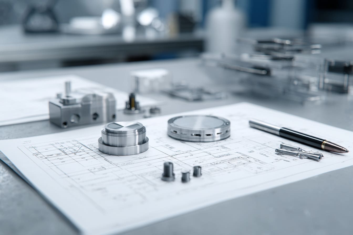
On a production drawing, “IP67” can look like the final answer. In real industrial use, it is often only the beginning of the question. I have seen a well-made enclosure shell arrive with a sound gasket and clean machining, then lose water resistance after a cable was changed, a lid was opened for service, or a machine spent a season cycling between hot days and cold nights.
An IP67 waterproof enclosure is intended to meet a defined ingress-protection test; it is not a promise that every installed version will survive every wet, dirty, vibrating, or poorly maintained environment. IEC 60529 defines the IP Code as a classification of protection provided by enclosures, while the final installation includes far more than the bare housing. IEC’s description of IEC 60529 is a useful starting point, but buyers still need to review the sealing system around it.
This is how I separate a credible IP67 enclosure design from an “IP67” label that becomes expensive after commissioning.
An IP67 Test Is a Defined Test, Not an Unlimited Service Guarantee
What the rating actually describes
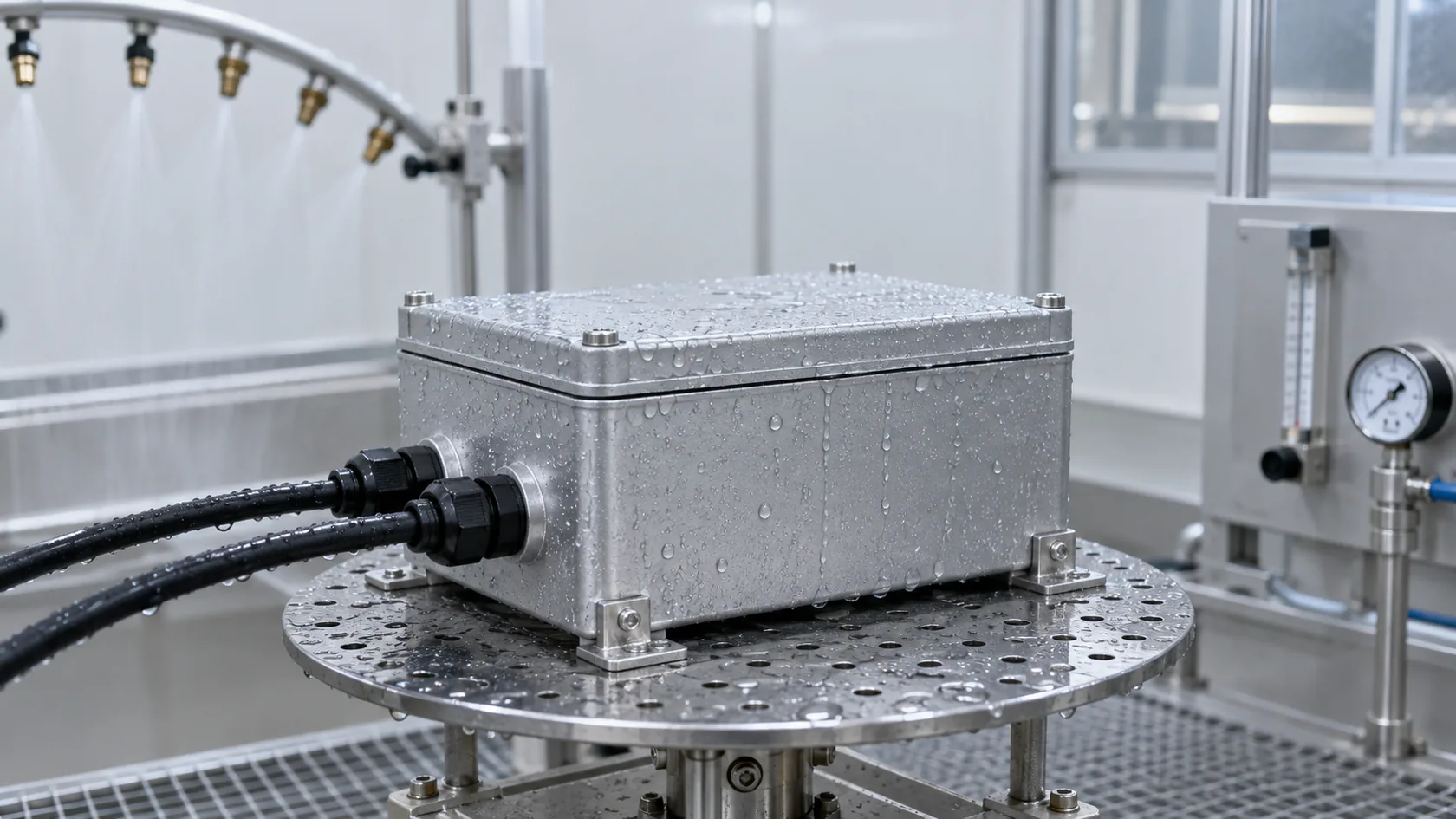
The “6” addresses dust ingress and the “7” addresses temporary immersion under the conditions specified by the applicable test. It does not automatically cover every liquid, pressure, duration, temperature, mounting position, or maintenance practice the product may face later.
For me, the practical trade-off is simple: a higher rating on the quote is useful only when the test configuration resembles the equipment’s real exposure. A compact sensor box beside a wash-down line, a controller on an outdoor gantry, and a junction box that can sit in a flooded pit need different questions even if all three ask for IP67.
Ask the supplier to state the test basis, the sample configuration, the cable-entry arrangement, and whether the lid was opened or changed after testing. That moves the discussion from a label to a repeatable design.
Cable Entries Usually Decide the Installed Rating
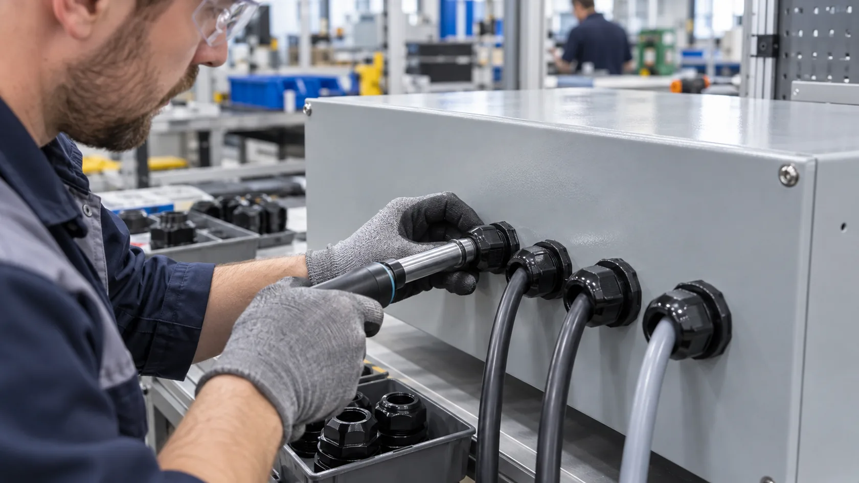
A rated gland still has limits
A cable gland needs the correct cable outside diameter, sealing insert, thread engagement, tightening torque, and panel hole. A gland chosen for a nominal cable size can leak if the actual cable jacket is undersized, oval, hard, or installed with the wrong torque. An adapter, reducer, plug, connector, or conduit fitting can create another seal path.
NEMA’s guidance for liquid-tight conduit makes the system principle very clear: the overall rating is limited by the lowest-rated component in the conduit-fitting-enclosure chain. NEMA Bulletin 123 also cautions that IP and NEMA ratings are not completely equivalent.
Before mass production, I would rather see the real customer cable, connector, and strain-relief plan than approve a generic hole chart. It is a small delay compared with reworking a sealed panel after installation.
The Lid Seal Fails When Compression Is Not Controlled
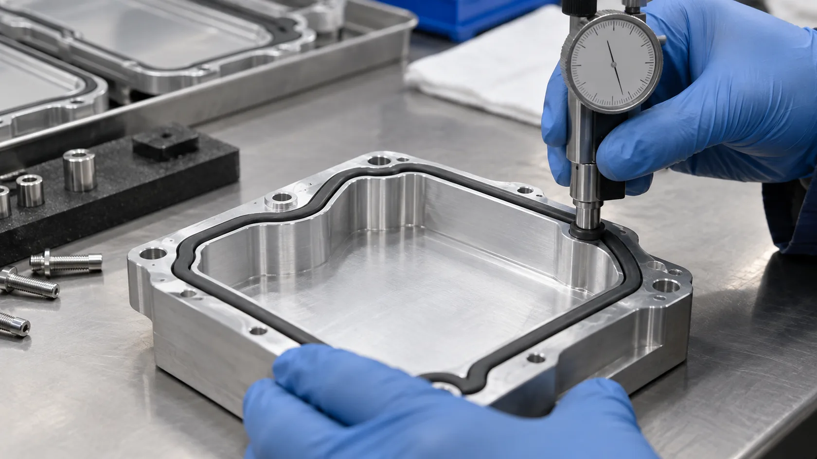
Gasket material is only one part of the seal
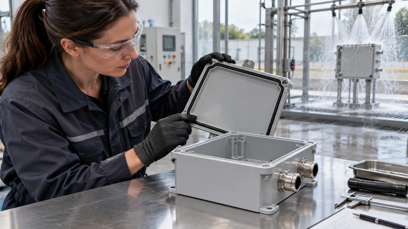
Foam, silicone, EPDM, and O-ring solutions can each work in the right geometry and environment. The gasket needs a continuous land, controlled compression, suitable corner treatment, and enough fastening stiffness to keep the cover from lifting between screws. A beautifully specified gasket cannot compensate for a warped cover, burrs across the seal path, uneven screw torque, or an over-painted groove.
| Check | Why it matters in use |
|---|---|
| Compression path | Uneven clamp load creates local leak paths. |
| Surface condition | Burrs, weld spatter, and texture can interrupt contact. |
| Fastener layout | Wide spacing can allow a cover edge to lift under load. |
| Service cycles | A removable cover repeatedly asks the seal to recover. |
For periodically opened covers, material suitability matters as much as the initial squeeze. UL’s explanation of its UL 50E gasket compression test distinguishes cellular gaskets used in periodic recompression from continuous-compression applications. I treat service access as a design input, not an afterthought.
Heat, Condensation, and Pressure Changes Work Against Static Seals
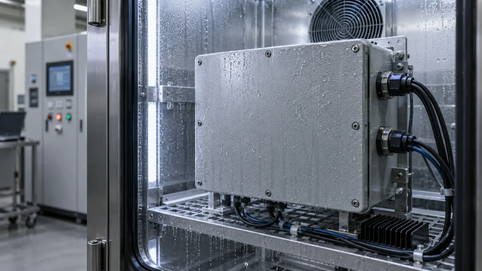
Water can appear from inside the enclosure
An enclosure can stay closed and still collect moisture. Warm air expands, cool air contracts, and thermal cycling can draw humid air through marginal interfaces. When internal surfaces cool below the dew point, condensation can form on terminals, PCBs, or the inside of a clear window.
More sealing can reduce direct water entry but also reduce passive breathing and heat rejection. That is why I do not treat a vent, heat sink, gasket, or coated cover as an isolated feature. The thermal path, mounting surface, internal heat load, cable entry, and any pressure-equalization solution need to be reviewed as one system.
Parker’s O-ring guidance notes that temperature range can require gland-design compensation for seal expansion or contraction. Its O-Ring Handbook is a useful engineering reference for why room-temperature assembly alone may not prove a seal through thermal cycling.
Installation and Orientation Create Failures the Lab Sample Did Not See
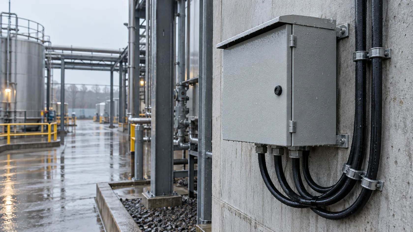
Gravity, vibration, and field work matter
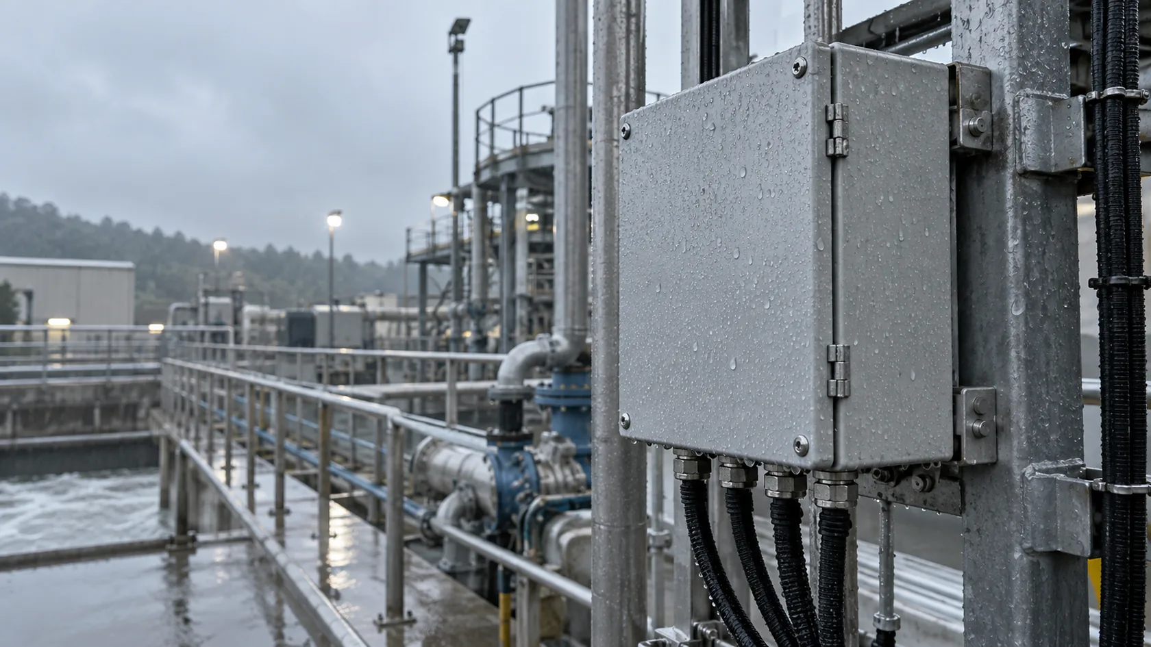
A gland that faces upward can become a standing-water point. A door seam placed under a drip edge behaves differently from one directly exposed to driven rain. Machine vibration can relax hardware, while a field technician may remove a cover and reinstall it with a different screw sequence.
The enclosure’s mounting angle, cable loop, exposed face, hose direction, and service access should be frozen before final validation. In outdoor work, I also look at cut edges, dissimilar-metal contact, finish damage, and drainage. Corrosion near a gasket land or threaded fitting can slowly change the geometry that originally sealed well.
This is also why a quick “add a drain hole” correction is risky. NEMA cautions that a drainage opening must not jeopardize the enclosure type rating. Its guidance on openings in wet-location boxes shows that drainage is a controlled design feature, not a drill-on-site fix.
Production Variation Can Turn a Good Sample into a Weak Series
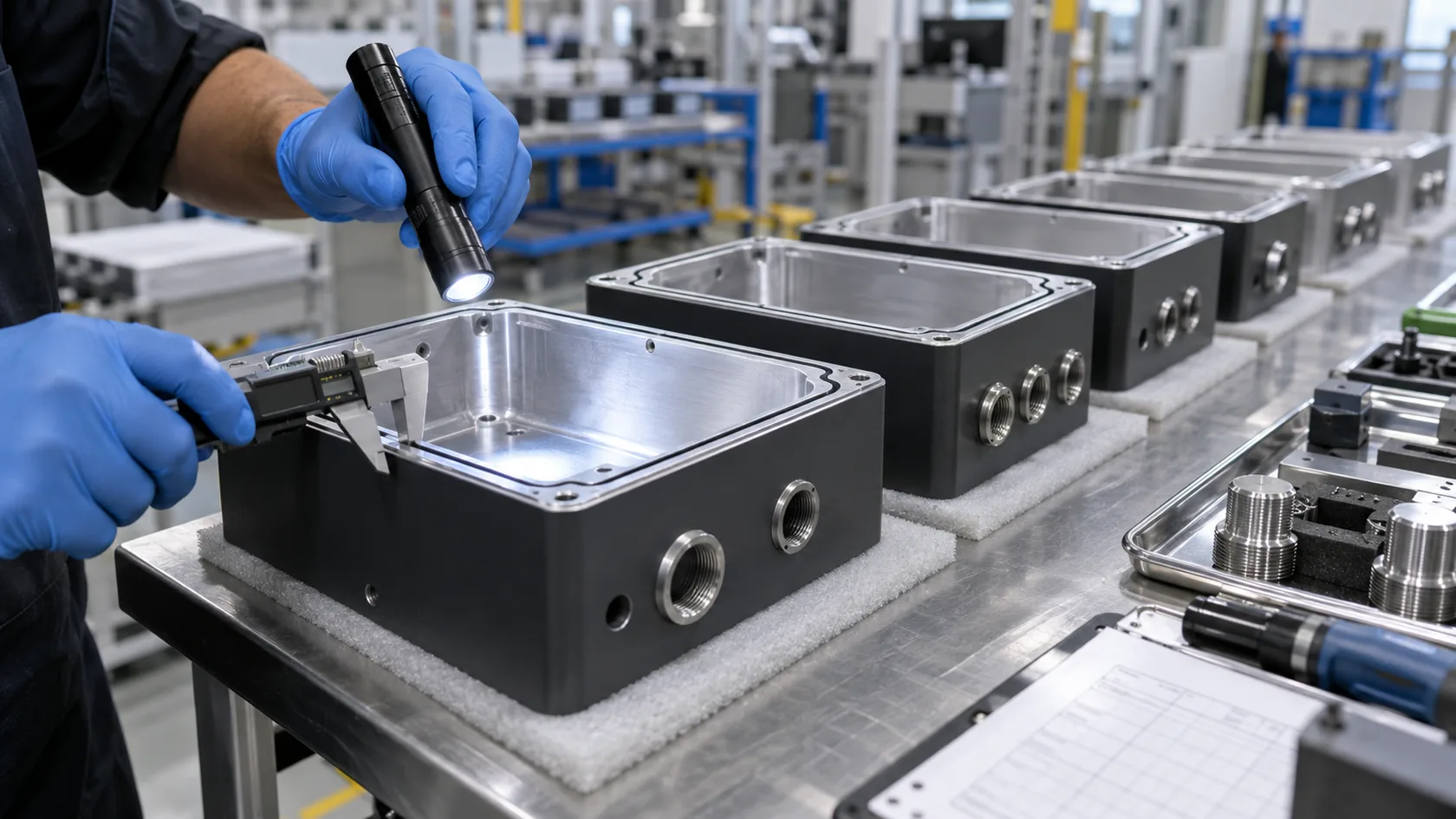
Control the details that affect the seal
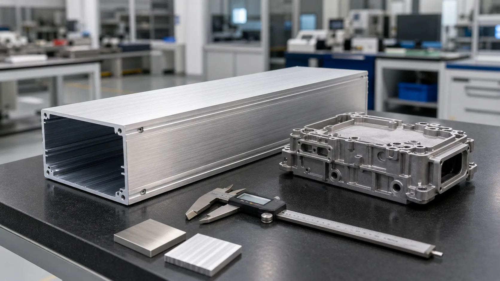
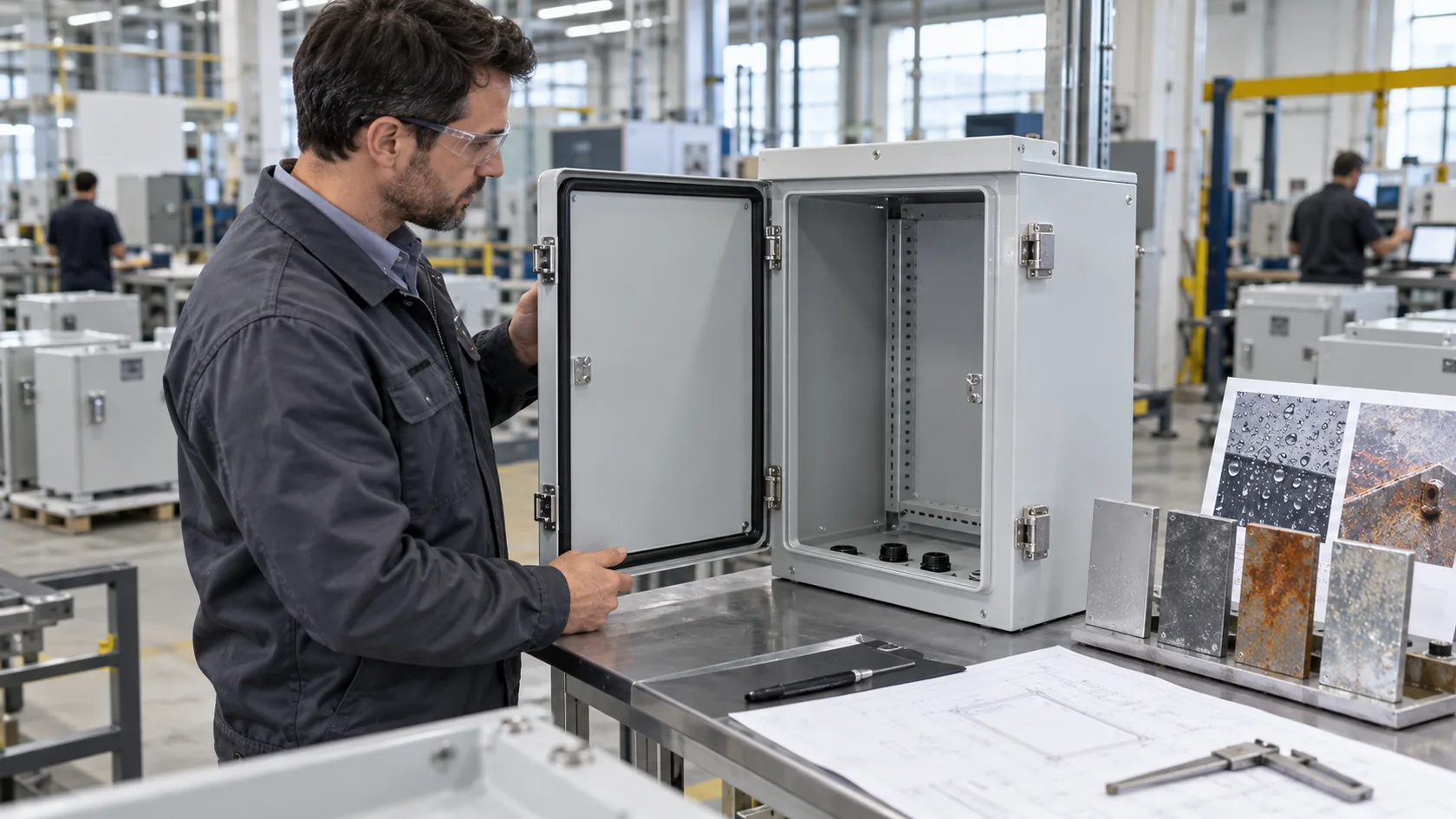
Prototype parts are often hand-checked by the people who built them. Production parts must survive variation in forming, machining, coating, gasket application, fitting torque, and assembly sequence. A sheet-metal cover can change with bend control; a die-cast body can need careful treatment around draft and flat sealing lands; a CNC enclosure can still lose consistency if a groove or threaded port is not inspected.
| Production control | Buyer or supplier evidence to request |
|---|---|
| Critical seal geometry | Drawing dimensions, inspection method, and acceptance limits |
| Gasket application | Approved material, lot control, joint location, and work instruction |
| Fastening | Torque specification and recorded assembly process where appropriate |
| Cable entries | Approved component list and cable-range verification |
| Final test | Defined sample plan, setup, and pass/fail record |
My preference is to identify the few dimensions and work steps that actually protect the ingress path, then inspect those consistently. Measuring every cosmetic feature while skipping lid flatness or gland torque is false confidence.
Validate the Complete Configuration, Then Protect It Through Service
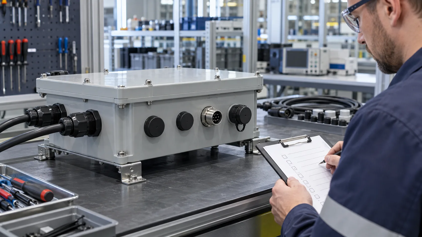
A practical buyer checklist
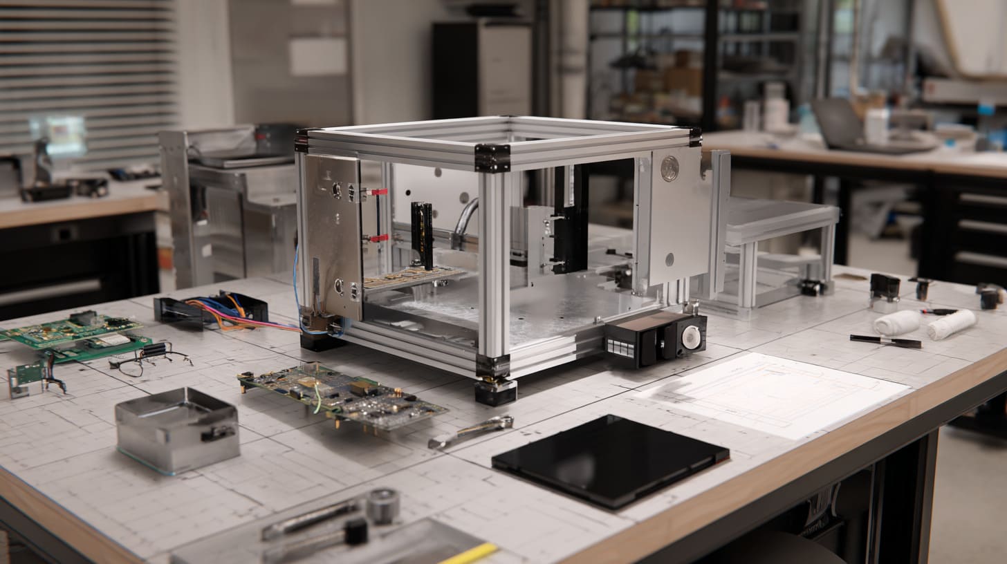
Before approval, use the intended enclosure, cover, gasket, fasteners, glands, plugs, connectors, cable sizes, and mounting orientation. Document the configuration and keep it stable. If the installation changes, decide whether the changed assembly needs a new review or test.
- Define the actual exposure: immersion, wash-down, rain, dust, UV, coolant, vibration, and temperature swings.
- Freeze the real cable and connector arrangement rather than testing blank holes.
- Confirm seal geometry, compression, fastener pattern, and torque method.
- Validate the finished assembly against the relevant requirement and record its configuration.
- Provide installers and service teams with the cable range, torque, replacement-gasket, and reassembly instructions.
UL notes that environmental-rated accessories can be evaluated for corrosion resistance, UV degradation, and their ability to maintain a seal against an appropriately rated flat enclosure surface. UL’s enclosure-accessory guidance is a good reminder to qualify handles, windows, fittings, and similar add-ons—not only the box.
Conclusion
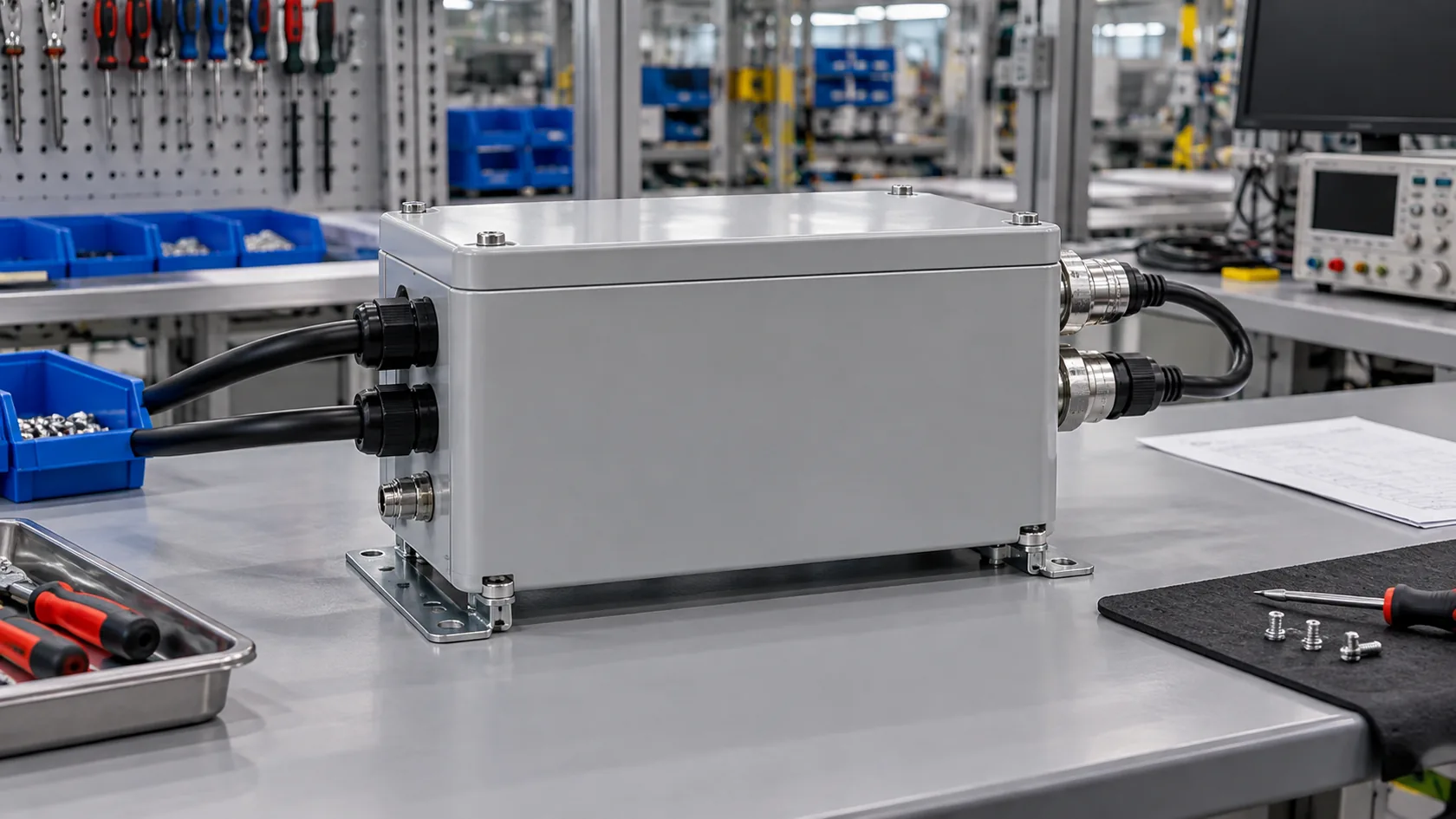
IP67 is valuable when it is treated as a verified design condition. It becomes unreliable when a shell rating is used to cover untested cable entries, uncontrolled gasket compression, condensation, field modifications, or production variation.
From the factory side, I trust the enclosure that has a documented seal path, specified accessories, practical assembly controls, and validation of the actual installed configuration. If you are reviewing a new industrial enclosure, send the drawing, cable-entry plan, exposure details, and service expectations. We can identify the weak links before they become a field-return problem.