Skip to content


The expensive mistake is easy to miss in a production meeting. A sheet-metal enclosure is ready for powder coating, the colour and texture are approved, and somebody adds “grounding point” to the notes. After cure, the enclosure looks excellent—but the only intended metal-to-metal interface is under an insulating finish.
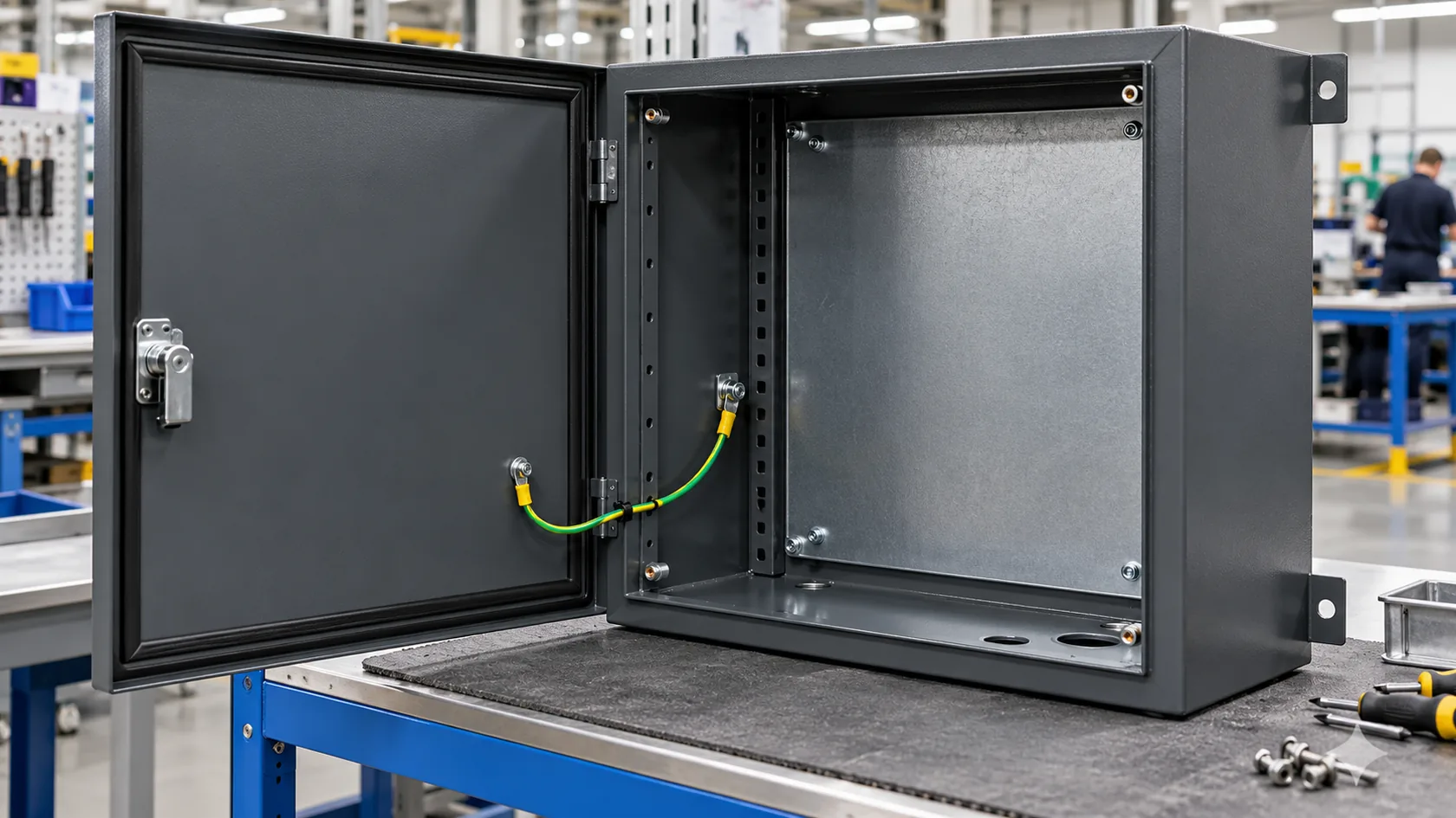
That is why I prepare grounding points before powder coating, not during final assembly. Powder coating is valuable corrosion and appearance protection, but it changes the surface stack-up. OSHA's US electrical rule is explicit that nonconductive paint or similar coating has to be removed at required threads, contact points, and contact surfaces, unless a fitting is designed to make that removal unnecessary. The practical lesson for an enclosure buyer is simple: define the intended conductive interfaces before the part reaches the coating line.
This is an enclosure-manufacturing guide, not a substitute for a product safety design or compliance decision. The electrical designer and the applicable product standard still determine whether a protective-earth path, functional bond, EMC interface, shield termination, or another connection is required. My role at the factory is to make the defined interface visible, repeatable, and practical to produce.
The first useful distinction is between the grounding that helps powder adhere and the grounding that the shipped product needs.
Separate the Product Bond From the Coating-Line Ground

Do not confuse coating-line grounding with the finished enclosure bond
During electrostatic powder application, the part needs a reliable path to the coating line. Clean racks, hangers, and contact points help powder deposition; the Powder Coating Institute notes that uncoated parts and clean hangers are good conductors, while powder build-up at contact points can degrade that path. That production connection is temporary. It does not prove that a protective-earth terminal, removable cover, mounting plate, cable shield, or EMC seam will work in the finished enclosure.
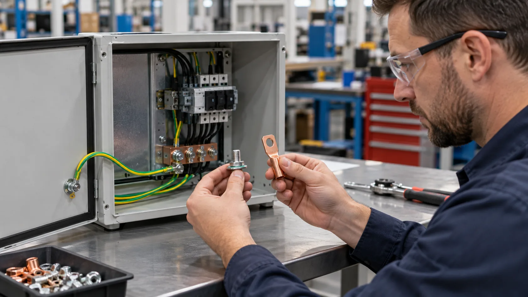
For the product, begin by asking what each connection must do. A protective-earth path may need to connect a defined terminal to conductive parts. A door or cover may need a deliberate bond if the product design requires it. A cable shield or conductive gasket may serve a separate EMC function. A low-resistance DC path does not, by itself, establish RF shielding or overall finished-product EMC performance.
| Interface question | What must be decided before coating | What should not be assumed |
|---|---|---|
| Protective-earth attachment | Terminal location, required mating surfaces, hardware, test basis | A painted screw head creates a qualified fault path |
| Removable panel or door | Whether a dedicated jumper or controlled joint is required | The hinge will remain a reliable electrical path |
| Internal chassis or subpanel | Defined contact route and assembly sequence | Every fastener automatically bonds through finish |
| Shield or EMC seam | Seam geometry, treatment, gasket or spring-contact plan, validation | A continuity beep proves EMC compliance |
I ask the buyer to name the electrical function at every point before discussing a masking method. It prevents a coater's temporary rack contact from being mistaken for the product's real grounding design.
Once the functions are separate, turn them into a short register that both engineering and finishing can read.
Make a Grounding-Point Register Before Detailing the Finish

Name each interface, its mating part, and its evidence
A grounding-point register is a small table or drawing layer, not a complicated new document. For each intended conductive interface, identify the enclosure part, the mating part, the electrical purpose, the finish boundary, the hardware or jumper, and the inspection evidence. This is where an ambiguous note such as “scrape paint for ground” becomes a buildable instruction.
Keep protective bonding, functional grounding, static control, and EMC interfaces separate in the register. Their acceptance conditions can be different. OSHA describes bonding as connecting conductive objects so they are at the same electrical potential; that concept is useful, but the specific method and acceptance criteria must still come from the product's responsible engineering and compliance plan.
| Register field | Example of a useful entry |
|---|---|
| Interface ID | PE-01, door bond DB-02, or the customer's own controlled identifier |
| Electrical role | Protective-earth path, internal chassis bond, or specified EMC interface |
| Parts and mating state | Enclosure body to terminal lug; door to body with the released strap installed |
| Finish instruction | Defined masked land or approved finish treatment; no informal removal instruction |
| Assembly control | Specified hardware stack, torque/process reference, or dedicated jumper |
| Evidence | Visual inspection, product-specified electrical test, or released validation record |
Avoid filling this table with invented resistance values or generic “pass” criteria. The accountable product team should define the method, instrument, current, limits, sample plan, and representative assembly state where those are required. I have seen a great deal of rework caused by a number copied into a drawing without any defined probes or test condition.
The register tells us what to preserve. The drawing must then tell production how to preserve it.
Turn Each Point Into a Buildable Drawing Feature
Define the contact land, hardware stack, access, marking, and owner
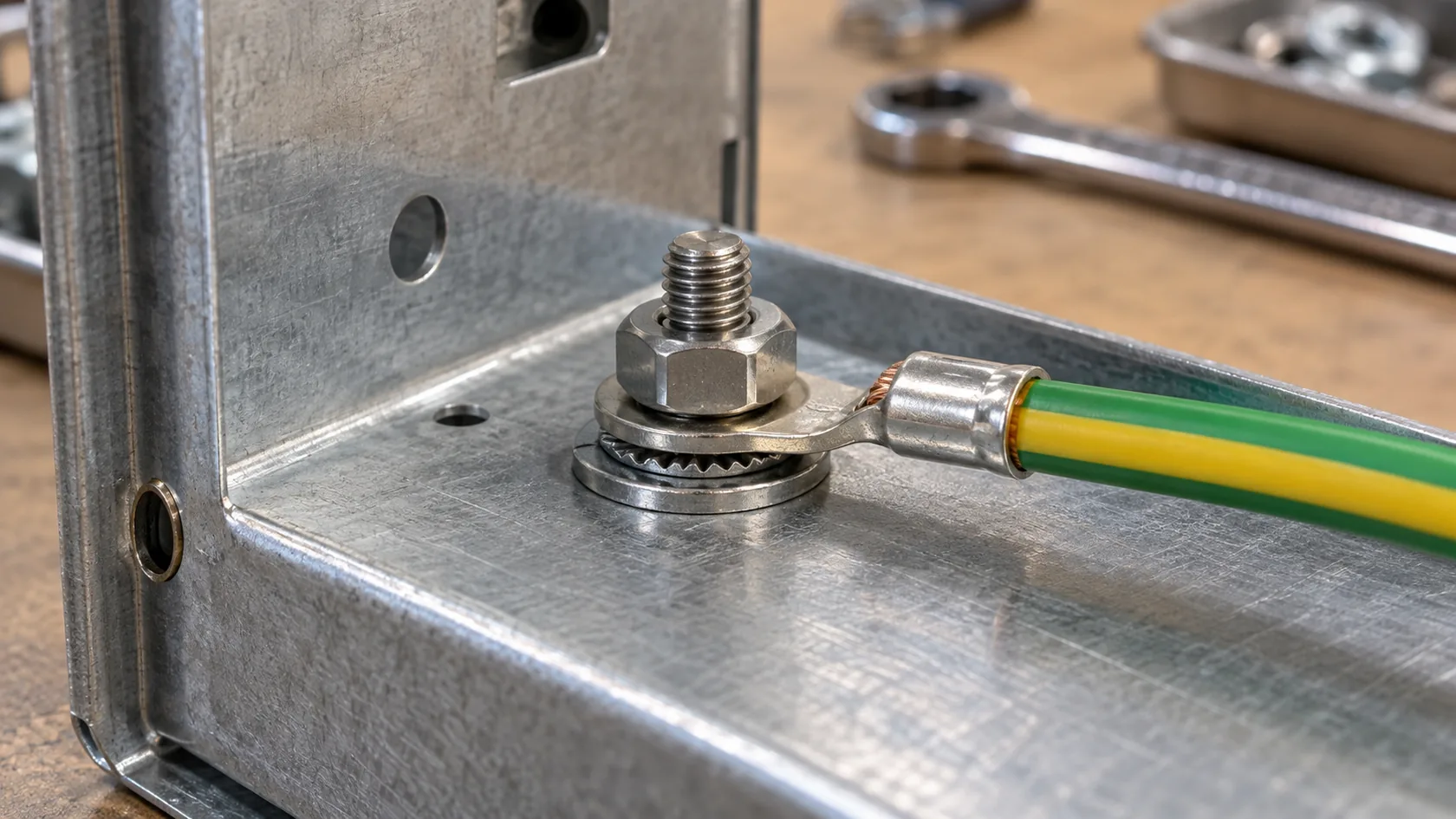
Every grounding point needs a physical feature that survives fabrication and can be reached after finishing. Depending on the design, that may be a controlled uncoated land, a purpose-designed terminal location, a dedicated jumper attachment, or an approved conductive treatment. The choice is conditional: geometry, base metal, environment, mating hardware, sealing, service access, and the product requirement all matter.
Show the feature on the released drawing. Include the extent of the finish exclusion or approved treatment, which surfaces mate, the required hardware stack, and which side of a formed panel carries the terminal. If the terminal needs a protective marking, specify the approved marking method so it remains legible after coating. Do not rely on an assembler to guess whether the paint-free circle belongs under a washer, around a stud, or on the opposite face of the panel.
For removable parts, make access practical. A bonding strap that can only be installed before a cover is painted or a fastener hidden behind a permanently fitted component creates a production trap. A deliberate contact land also needs enough surrounding clearance that a tool, probe, or replacement part can reach it without damaging the cosmetic finish or a gasket.
In my experience, the best grounding point is not the smallest possible bare-metal spot. It is the smallest controlled interface that can be assembled, inspected, protected, and serviced without argument.
With the feature defined, the next release item is the mask itself.
Specify the Masking Plan, Not a Last-Minute Paint Scratch
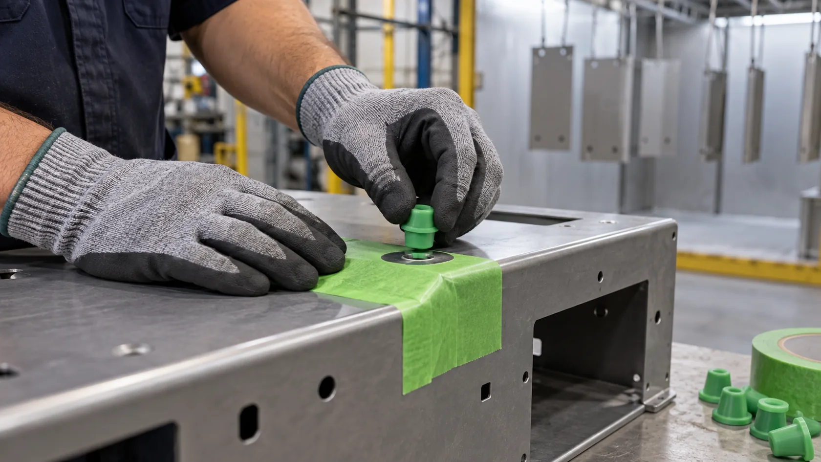
Give the coater a revision-controlled mask map and a clear edge condition
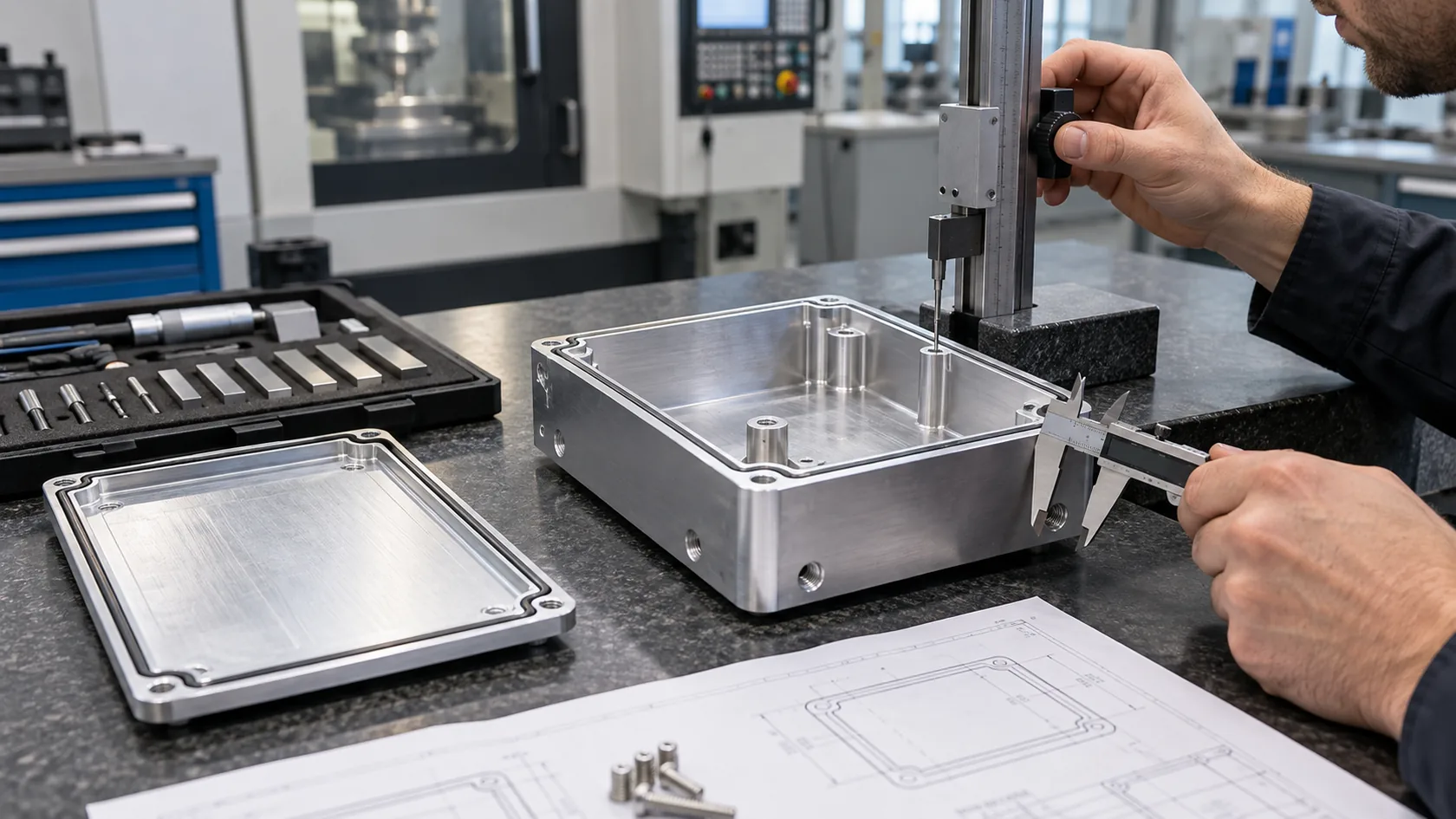
Powder-coating masking is a production operation: it covers an area to prevent powder deposition. The Powder Coating Institute defines it exactly that way. Put the required mask locations on a finish drawing or a controlled mask map, keyed to the grounding-point register. State the part revision, mask ID, location, surface boundary, and inspection view. A clear photo of the uncoated part is often useful beside the drawing.
Choose masking materials and placement that suit the actual curing cycle and geometry. For example, 3M notes that powder-coating tapes must remain in place during bake cycles and remove cleanly; plugs, caps, and purpose-made masking may be more appropriate for holes, threads, and complex edges. That is a process-selection issue, not permission to use a random tape in a hot oven.
The mask plan should answer these factory questions:
- What exact area must remain free of coating, and on which side of the part?
- Is the interface a flat land, stud face, thread, bore, flange, or a more complex formed feature?
- Which masking method is approved, and who confirms it after removal?
- Does the mask edge interfere with a gasket, label, cosmetic surface, or seating face?
- What happens if masking shifts, leaves residue, or damages the edge during removal?
Never make “scrape paint as needed” the normal control. It makes the electrical contact, corrosion exposure, and cosmetic damage dependent on whoever is holding the tool that day. A mask map makes the intended uncoated interface part of the product definition.
The map also needs to be compatible with how the coater actually handles the part.
Hand Off a Part the Coating Line Can Process Reliably
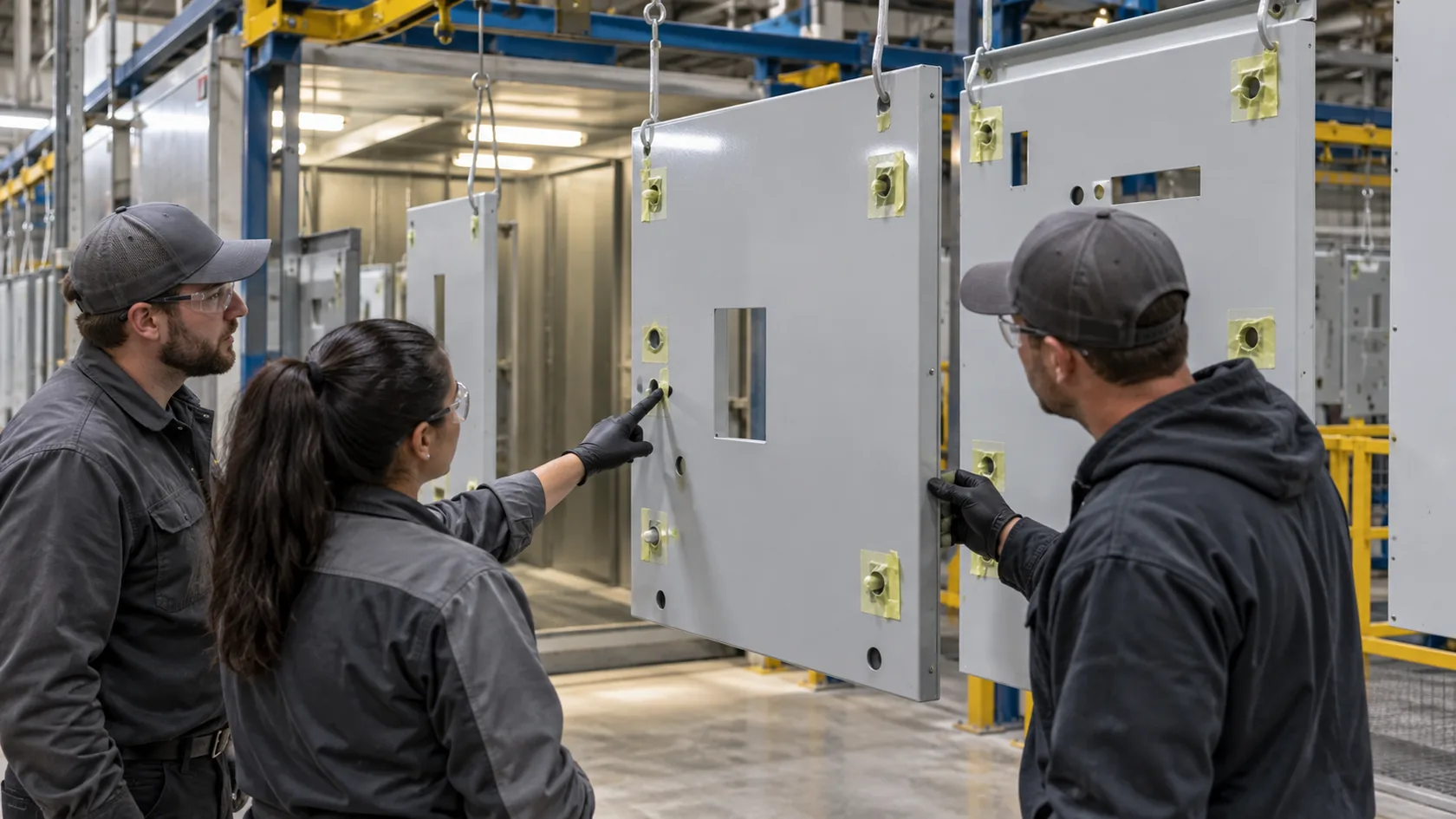
Review racking, handling, cure exposure, and protected threads
Before production, let the enclosure fabricator and coater review a representative part together. The coater needs workable rack locations and clean electrical contact for application. The product needs its final grounding land preserved exactly where the released design expects it. Those can be different locations, and the work instruction should show both.
Check whether a rack hook, clamp, or fixture will touch a cosmetic face, a sealing surface, a designated grounding land, or a thin flange that can mark or distort. A line contact mark may be acceptable only when it is intentionally located and documented. Do not quietly reuse a product grounding point as a hanging point if handling wear, masking movement, or a later assembly step could alter the interface.
Also review the cure process against every non-metal item that is deliberately installed before coating. In most cases, grounding hardware, flexible straps, electronics, labels, and elastomeric seals are better kept out of the coating cycle unless the released process specifically qualifies them. The Powder Coating Institute describes powder coating as a process in which powder is deposited and then fused into a continuous film by heat or radiant energy, so the cure stage is not a harmless storage step for nearby components.
I prefer a simple pre-coating traveler with an unmasked/masked check, a rack-location check, and a post-cure visual check. It costs very little compared with stripping, refinishing, and explaining why the final assembly no longer matches the drawing.
Even a perfectly placed land needs an environment-aware joint after the masks come off.
Protect the Exposed Interface for Its Service Life
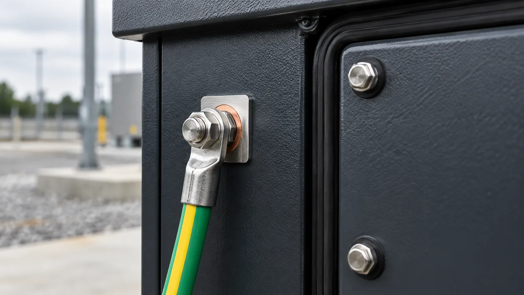
Balance conductivity, corrosion protection, sealing, and maintainability at the actual joint
An exposed grounding land is not automatically a durable grounding point. Bare or specially treated surfaces, dissimilar metals, trapped moisture, loose hardware, cleaning residues, and repeated service can change the joint over time. The right approach depends on indoor or outdoor exposure, condensation, salt or chemical risk, maintenance access, base metal, mating materials, and the approved electrical function.
Protect only what the design allows. A coating that bridges the contact can insulate it; an uncontrolled corrosion compound or sealant can do the same. Conversely, leaving a large bare area simply because it is easy to contact can create a corrosion and cosmetic problem. Plan the contact land, its hardware, drainage or orientation where relevant, and any approved protective treatment as one interface.
For an ingress-rated enclosure, the electrical plan must coexist with the enclosure joint, gasket compression, cable glands, fasteners, drainage, and installation orientation. Do not assume that a paint-free area near a cover seam is harmless to water resistance. Likewise, do not equate a coating decision with an IP, NEMA, safety, or EMC result; those are configuration- and test-basis-dependent outcomes.
I am cautious about designs that solve conductivity by enlarging a bare patch. Usually the more durable answer is a controlled small interface, suitable hardware, and a review of the real service environment before the finish is released.
Now test the whole sequence on a first article rather than discovering the conflict during a production run.
Release the First Article Before Repeating the Process

Inspect the complete assembly and lock the evidence together
The first coated article is where the drawing, mask map, hardware, assembly sequence, and finish quality meet. Inspect the specified land before assembly: confirm its location, finish boundary, cleanliness, edge condition, and accessibility. Then install the released hardware, strap, panel, or terminal and perform the product-defined inspection or electrical verification on the representative assembly.
If the product requires a continuity or protective-bond test, use its approved method. Document the actual drawing and finish revisions, probe locations, assembly state, instrument/fixture identity, and any defined acceptance evidence. Do not turn a convenient multimeter beep into a safety or EMC certificate. The relevant standard, test plan, and qualified compliance responsibility remain with the product owner.
Release the process only when these items agree:
- The mechanical drawing and grounding-point register identify the same interfaces.
- The mask map preserves those exact features after cure.
- The coater's rack and handling instructions do not damage or substitute for them.
- The final assembly uses the specified hardware or jumper in the intended order.
- The inspection record can be repeated after a drawing, finish, hardware, or process change.
This is also the right time to agree on change control. A different powder supplier, revised cure profile, new door hardware, altered fastener, coating thickness change, or mask substitute can matter if it touches the controlled joint. Treat it as an interface review, not just a cosmetic change.
That early discipline lets the finish team protect the enclosure without accidentally changing its electrical intent.
Conclusion
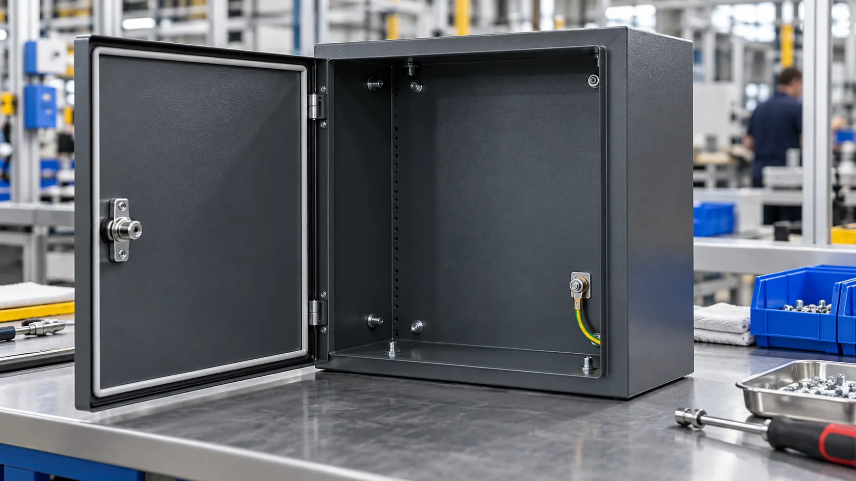
Preparing grounding points before powder coating is less about finding a clever way to remove paint later and more about making one clear manufacturing decision early. Separate the temporary coating-line ground from the finished product bond, register each required interface, show the contact feature and mask boundary on controlled documents, hand the part to the coater with realistic racking instructions, and prove the sequence on a first article.
After years of working through custom enclosure details, I trust a grounding point when the engineer, sheet-metal team, coater, and final assembler all see the same interface in their own instructions. If you are releasing a powder-coated enclosure, send the drawing, intended bonding or grounding functions, finish specification, service environment, and relevant test basis. We can review the contact and masking plan before the coating line turns a small unclear note into a costly production change.