Skip to content
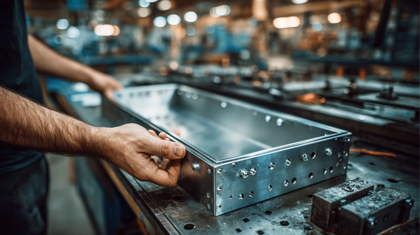
A metal enclosure can look serious, clean, and expensive on the bench, yet still fail EMI shielding because of something that seems almost too small to care about.
Sometimes that weak point is the screw layout.
I have seen teams spend hours discussing board layout, cable routing, grounding points, and filter choices. Then the test result comes back, and the real problem is sitting right on the seam. Not the big design choice. Not the expensive part. Just a lid, a row of screws, and too much space between them.
That is why I think this topic deserves more respect than it usually gets.
People often treat screw count as a cost line. Fewer screws mean less hardware, less machining, and faster assembly. On paper, that sounds neat. In real work, it can turn into a very annoying mistake. A seam that looks tight to the eye may still leak in electrical terms. A cover that feels “good enough” by hand may still behave badly in a test chamber.
The part that makes this tricky is simple: EMI shielding does not only depend on material. It also depends on contact. Real contact. Stable contact. Repeated contact across the seam, not just at a few isolated points.
I do not judge a screw layout by how clean it looks in CAD. I judge it by whether the seam stays electrically useful after coating, assembly, handling, vibration, and time.
That is where fewer screws start creating more problems.
And once you see that pattern in one project, you start noticing it everywhere.
Why Do Screws Matter in EMI Shielding Enclosures?
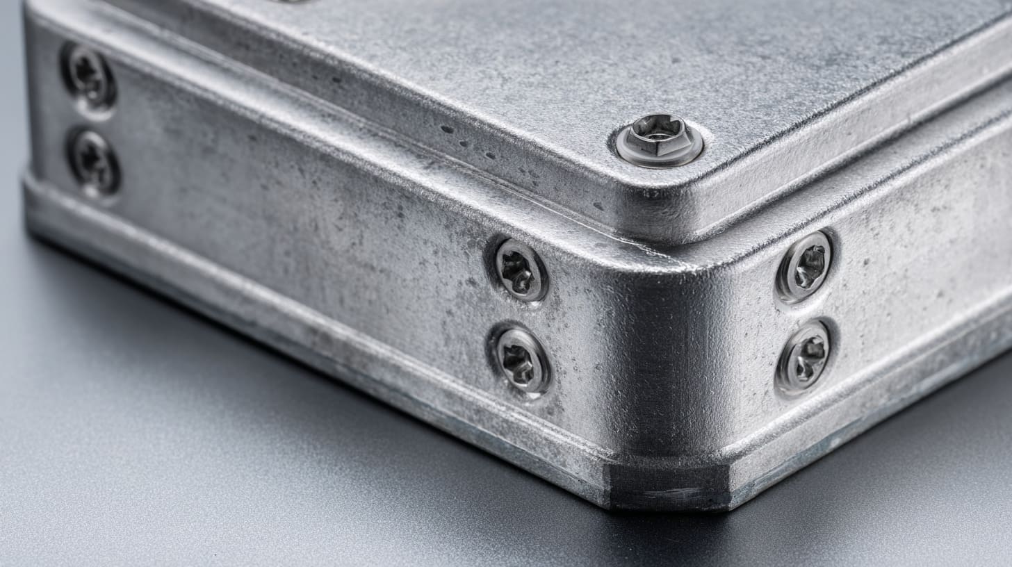
I think many people see screws as a purely mechanical detail. They hold the lid down. They keep parts aligned. They help the product survive shipping and use. All of that is true. But in an EMI shielding enclosure, screws often do one more job. They help build the electrical path across the seam.
That changes how I look at them.
If the enclosure is meant to shield noise, the metal body has to act like one connected shell. The moment that shell becomes electrically weak at the joints, the shielding performance starts to drop. That is why screw count and screw spacing matter so much more than many buyers or even engineers expect.
A nice-looking housing can still perform badly if the conductive path is broken again and again along the edge.
Electrical Continuity vs Mechanical Fastening
Mechanical fastening and electrical continuity are related, but they are not the same thing.
A screw can pull two panels together. That helps structure. But EMI shielding asks for more. It asks for reliable metal-to-metal contact along the seam, not just force at isolated spots. A row of screws creates repeated bridges. Each bridge gives current another chance to pass from one panel to the other.
If there are too few screws, those bridges are too far apart. The panels may still feel secure in a mechanical sense. But electrically, the path becomes weak, uneven, or unstable.
I have seen this confusion many times. Someone tightens a few screws, presses on the lid, and says, “It’s solid.” That statement may be true for structure. It may be totally wrong for shielding.
| Mechanical view | EMI view |
|---|---|
| Does the cover stay in place? | Does the seam stay conductive? |
| Can it survive handling? | Can current pass across the seam consistently? |
| Does it feel tight? | Is contact stable along the full edge? |
| Are there enough fixing points? | Are there enough conductive contact opportunities? |
This is one of those areas where a product can pass one test in your hand and fail another test in the lab.
Contact Resistance at Seams
Contact resistance is where the problem gets real.
Even when two metal parts touch, they do not always touch well. Surface roughness, coatings, oxidation, dirt, and pressure all matter. The actual current does not flow through the whole visible area. It flows through tiny real contact points. That is why seam design can be deceptive.
When screw count drops, pressure becomes more uneven. Areas close to the screws may press well. Areas farther away may not. The seam can start behaving like a chain with missing links.
This is where I stop trusting appearance. I have seen anodized aluminum parts look beautiful and fit beautifully, yet the oxide layer quietly blocks the electrical path people thought they had.
Here is a simple way I think about it:
- More screws usually mean more pressure points
- More pressure points often mean better contact consistency
- Better contact consistency usually means lower seam resistance
- Lower seam resistance usually helps EMI shielding
But there is a catch. Screw count alone is not enough. If the contact area is coated, dirty, or badly designed, adding screws may only partly help.
| Seam condition | Likely result |
|---|---|
| Bare metal contact + good pressure | Lower resistance |
| Anodized contact area + limited pressure | Higher resistance |
| Few screws + long seam | Uneven resistance |
| Many screws + poor surface prep | Better than few screws, but still risky |
That is why I never look at screw layout alone. I look at the screw layout and the contact surface together.
Shielding Effectiveness and Leakage Paths
A gap between screws is not just empty space. At the wrong frequency, it can behave like a leakage path.
That is the part many people miss.
A seam does not need to open dramatically to become a problem. A tiny discontinuity can still let high-frequency energy escape. The enclosure may still look closed. It may still feel robust. But electromagnetically, that long unsupported section between screws can act more like an opening than a shield.
I do not like treating seams as cosmetic lines. I treat them as risk lines.
The higher the frequency, the less forgiving the seam becomes. A product that seems acceptable at lower frequencies can become much more sensitive at higher ones. This is why sparse screw layouts often create painful surprises in EMC work. The design looks efficient at first. Then the seam behaves like a weak antenna.
A simple comparison helps here:
| Seam layout | EMI behavior |
|---|---|
| Short gaps between screws | Better control of leakage |
| Long gaps between screws | Higher risk of slot-like leakage |
| Uniform pressure | More stable contact |
| Uneven pressure | More unpredictable shielding |
I have learned to be suspicious of any design that saves a few screws while asking the seam to do too much work.
That is where the next problem starts. Once screw count goes down, the seam itself begins to change in ways people do not notice right away.
What Happens When You Use Fewer Screws?
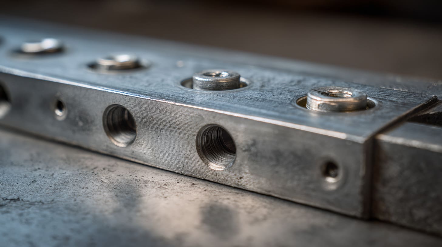
The first thing many people notice is cost. The second thing is assembly speed. The third thing, sadly, often comes much later, when the enclosure starts behaving worse than expected.
Using fewer screws usually sounds harmless. Sometimes it even sounds smart. You reduce hardware, cut machining time, and make assembly look simpler. But in shielding work, simpler is not always safer. Fewer screws can create a seam that is mechanically acceptable and electrically unstable at the same time.
That split is where many bad decisions are born.
What makes this even more frustrating is that the problems do not always show up in an obvious way. The enclosure may look flat. The lid may feel secure. The first sample may even pass a rough bench check. Then vibration, heat, handling, or frequency exposure starts revealing what the eye missed.
I pay close attention when cost reduction touches fastener count, because cheap changes at the seam have a bad habit of becoming expensive changes after testing.
Increased Seam Gaps
The most direct result of fewer screws is longer unsupported distance between fastening points.
That matters more than it sounds.
A metal panel is not perfectly rigid. A lid can flex. A base can move slightly. Tolerance stacks can add up. Once the gap between screws gets longer, the seam becomes easier to bend, lift, or relax in the middle. You may not see a dramatic gap, but even a tiny loss of contact can matter for shielding.
I have seen lids that looked perfectly fine when screwed down at the corners. Then I pressed near the middle of the edge and felt just enough movement to worry me. That tiny movement told the real story.
Here is how the problem usually grows:
- Screw count is reduced.
- Unsupported seam length increases.
- Pressure becomes uneven.
- Small seam openings appear between screws.
- EMI leakage risk rises.
| Screw layout | Typical seam behavior |
|---|---|
| Dense, even spacing | Better edge support |
| Sparse, wide spacing | More mid-span flex |
| Corner-focused fastening | Weak middle sections |
| Mixed spacing with long open runs | Unstable contact zones |
The dangerous part is that these gaps can be microscopic and still matter.
Higher EMI Leakage Risk
Once gaps get longer, the leakage risk goes up.
That is where the electrical problem becomes more serious than the mechanical one. Long seam sections between screws can act like narrow radiating openings. The enclosure is still “closed” in a common-sense way, but not closed enough in an EMI sense.
This is one of those details that can really fool people. If you are not used to EMC work, it is easy to think a tiny seam is basically no seam. But high-frequency energy does not think the way a buyer or a factory manager thinks. It finds the weak path.
I often explain it like this: shielding does not fail only through big holes. It also fails through badly controlled edges.
A sparse screw layout tends to create three kinds of risk:
- Longer leakage path
- Less uniform seam pressure
- More variation from unit to unit
That last point matters a lot in production. One sample may look okay. Another may behave worse because of normal tolerance variation. That makes EMC results less predictable, and unpredictable results are expensive.
| Risk factor | Effect on shielding |
|---|---|
| Long seam gap | Higher chance of leakage |
| Poor contact repeatability | Inconsistent performance |
| Higher frequency operation | Stronger sensitivity to seam weakness |
| Production tolerance variation | More test uncertainty |
A design that depends on “probably okay” seam contact is a design I do not trust much.
Mechanical Deformation Over Time
This is where things become even less forgiving. Time starts working against the design.
Heat cycles, vibration, shipping shock, repeated opening and closing, and simple material stress can all reduce contact quality over time. When there are fewer screws, each screw carries more responsibility. The seam has fewer points holding pressure and alignment. That means small mechanical changes can have a larger effect.
I have seen enclosures that seemed decent at first build, then became less convincing after normal handling. Not broken. Not visibly damaged. Just less stable. That kind of slow drift is dangerous because it does not announce itself loudly.
A few common causes make it worse:
- Thermal expansion and contraction
- Panel warp
- Screw relaxation
- Repeated maintenance opening
- Transport vibration
| Time-related factor | What can happen |
|---|---|
| Heat cycling | Contact pressure changes |
| Vibration | Fasteners loosen slightly |
| Rework or service opening | Seam fit becomes less consistent |
| Thin cover panels | Flex increases over time |
I get nervous when a design relies on very few screws and also expects long-term stability in a harsh environment. That combination often looks efficient in the drawing and fragile in the field.
This leads to the next question people usually ask me: how much spacing is too much? That is where the discussion stops being abstract and starts becoming very practical.
How Screw Spacing Affects Shielding Performance
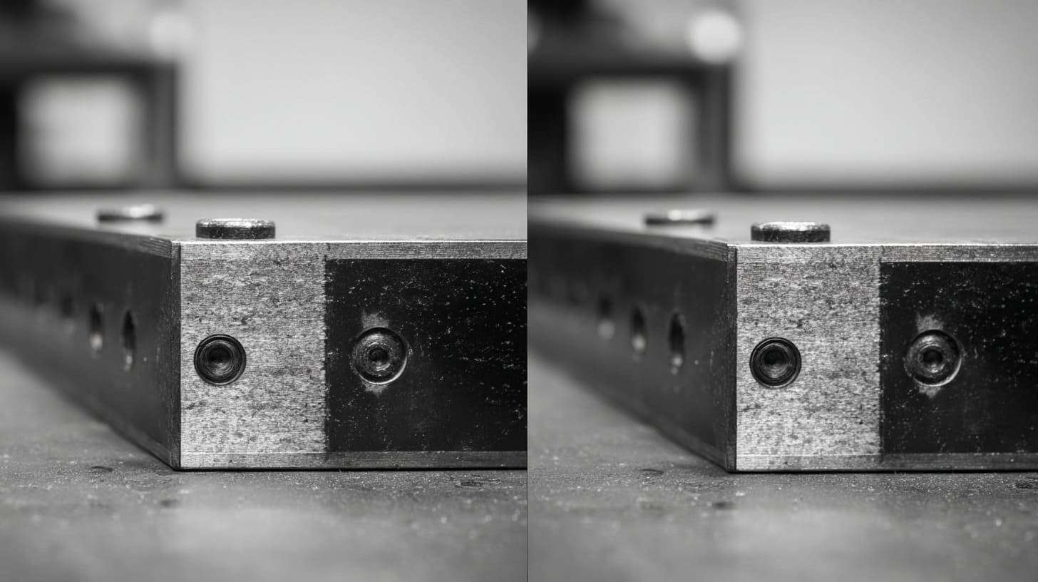
Screw spacing is not just a layout choice. It is part of the shielding strategy.
I think this is the point where many conversations finally become honest. At first, people argue about hardware count, assembly speed, or machining cost. Then once frequency enters the discussion, the room changes a little. The screw pattern is no longer just a mechanical drawing detail. It becomes an electrical design issue.
That shift matters.
The right spacing depends on what the enclosure is trying to contain or block. A low-frequency industrial box and a high-frequency communication product do not ask the seam to do the same job. That is why copying a screw pattern from an old project can be risky. Similar shape does not mean similar EMI behavior.
When I review a fastener layout, I do not start by counting screws. I start by asking what frequency range the seam needs to survive.
Relationship Between Gap Length and Wavelength
A longer gap is more dangerous when the frequencies are higher.
That is the basic idea.
As wavelength gets shorter, seam openings become more meaningful. What looks tiny to us may still be large enough, relative to wavelength, to create leakage trouble. That is why a screw spacing that works for one product may fail badly in another.
I do not think it helps to treat the 1/20 wavelength rule as a magical answer, but I do think it is a useful design warning. It reminds people that seam length and signal frequency are connected. Once the gap becomes too long compared with the wavelength involved, the risk grows fast.
Here is a simplified view:
| Frequency | Wavelength trend | Tolerance for seam gap |
|---|---|---|
| Lower frequency | Longer wavelength | More forgiving |
| Mid frequency | Medium wavelength | Moderate caution needed |
| Higher frequency | Shorter wavelength | Much tighter seam control needed |
This does not mean every project needs extreme screw density. It means every project needs the spacing to match the electrical reality.
That is the part I care about. Not theory by itself, but theory applied to a real product.
Recommended Screw Spacing Guidelines
General guidelines help, but I never treat them as universal truth.
A common rule is to keep spacing below about one-twentieth of the wavelength of concern. That gives engineers a starting point. It is useful. Still, real projects also depend on gasket design, seam geometry, panel stiffness, surface finish, and expected environment.
So I use guidelines as a first filter, not a final answer.
A practical view looks more like this:
| Design factor | What I consider |
|---|---|
| Operating frequency | Higher frequency needs tighter spacing |
| Enclosure size | Larger panels may need extra support |
| Seam shape | Straight long seams are more sensitive |
| Material thickness | Thin panels can flex more |
| Surface treatment | Coated seams may need extra help |
| Target compliance level | Tougher EMC targets need more margin |
I have found that trouble often begins when teams use a “reasonable-looking” spacing without tying it to the actual frequency behavior of the product. That is where guesswork sneaks in.
And guesswork at the seam is expensive.
Case Comparison: Dense vs Sparse Fastening
A direct comparison makes the point clearer.
I have seen dense fastening layouts that looked slightly overbuilt but passed more smoothly. I have also seen sparse layouts that looked elegant in CAD and became a headache later. The sparse version usually wins the beauty contest. The dense version often wins the EMC fight.
That does not mean dense is always right. It means sparse has less margin for error.
| Feature | Dense fastening | Sparse fastening |
|---|---|---|
| Seam support | More uniform | Less uniform |
| Contact consistency | Better | More variable |
| Leakage risk | Lower | Higher |
| Assembly time | Longer | Shorter |
| Hardware cost | Higher | Lower |
| EMC predictability | Better | Less stable |
This is where I often have to make a judgment call. If the product is sensitive, the environment is harsh, or the compliance target is strict, I would rather defend a few extra screws than defend a failed test later.
That still leaves a fair question, though. Can engineers go too far the other way? Yes. They can. And that matters too.
Are More Screws Always Better?
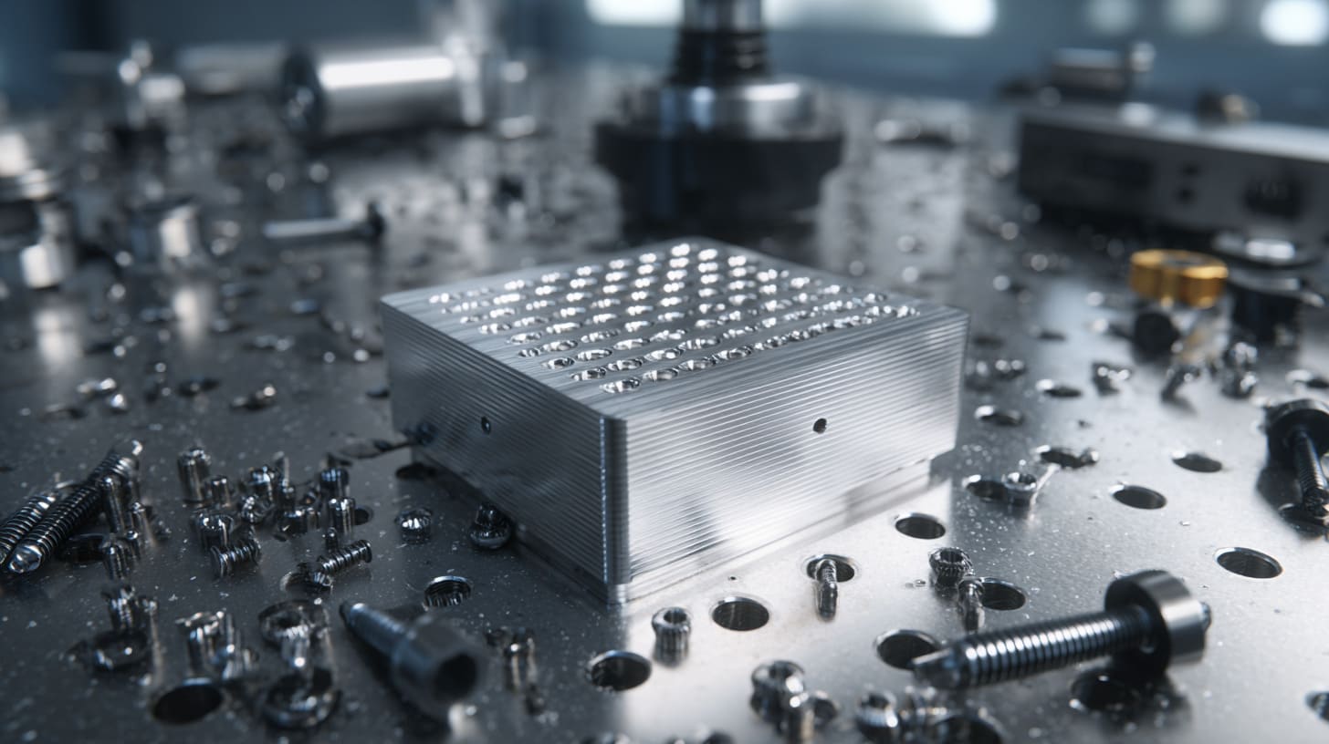
No, more screws are not always better.
I say that carefully because it is easy to swing too far once people understand the danger of using too few. Then the design starts collecting screws like a nervous habit. That can solve one problem and create three new ones.
I have seen that happen too.
A very dense screw pattern can improve contact, but it can also slow machining, complicate assembly, add tolerance headaches, and make maintenance annoying. It can even make a product feel overworked from a design point of view. Good engineering is not about stuffing in as many screws as possible. It is about getting enough conductive stability without making the product harder, slower, or more expensive than it needs to be.
When I look at a screw pattern, I am not chasing the biggest number. I am trying to find the point where performance margin still makes sense.
Diminishing Returns in Screw Density
There is a point where extra screws stop giving much extra benefit.
That point is different from project to project, but the pattern is real. Early screws often bring major improvement because they shorten gaps and increase contact points. Later screws may bring only small gains while continuing to add cost and process burden.
This matters because engineering time is limited. Budget is limited. Assembly time is limited. If I can get solid shielding with a smart screw layout and a good gasket strategy, I do not need to force extra screws into every edge.
| Screw count trend | Typical impact |
|---|---|
| Too few | Big EMI risk |
| Moderate and well-placed | Best balance in many cases |
| Very high count | Small extra benefit, bigger process burden |
I become skeptical when a design adds screws simply because nobody wants to think through better seam design.
Manufacturing Complexity and Cost Impact
Each screw is not just a screw.
Each one may mean another hole, another tapped feature, another alignment point, another chance for tolerance stack-up, another item to install, and another step to inspect. On paper, one more screw looks cheap. Across production volume, it adds up.
That is especially true in custom projects where machining time and assembly rhythm already matter. If the enclosure needs fast turnaround, good cosmetic control, and repeatable fitting, excessive fastening can start hurting efficiency.
Here is how I usually see the trade-off:
| Added screws | Possible downside |
|---|---|
| More machining operations | Longer cycle time |
| More hardware handling | Slower assembly |
| More alignment dependency | Fit-up issues |
| More opening steps for maintenance | Poor service experience |
A design should not make factory work harder without a clear reason. I respect good EMI control, but I also respect clean production logic.
Design Balance: Performance vs Cost
This is the real design job. Not “more” or “less,” but “enough, in the right place.”
I think the best enclosure work usually comes from balance. The engineer understands the frequency risk. The buyer understands the cost pressure. The factory understands assembly reality. When those three views meet, the screw layout becomes smarter.
I often ask myself a few simple questions:
- Where is the seam most vulnerable?
- Which edges need tighter control?
- Can surface prep improve contact enough to reduce screw burden?
- Would a gasket solve the problem better than extra fasteners?
- Does the product need service access later?
| Goal | Best design attitude |
|---|---|
| Lowest hardware cost | Risky if overdone |
| Best shielding only | Can become overbuilt |
| Best production balance | Usually the strongest long-term choice |
I do not like designs that save cents and lose reliability. I also do not like designs that add hardware because nobody wanted to think harder. The better answer is usually somewhere in the middle.
And that middle becomes easier to find once we stop thinking only about screws and start looking at the other tools available.
Alternatives to Increasing Screw Count
Sometimes adding screws is the right move. Sometimes it is the lazy move.
I do not say that to be harsh. I say it because many shielding problems are really contact problems, not hardware-count problems. If the seam is poorly designed, dirty, coated, or too flexible, adding a few more screws may help, but it may not solve the real weakness.
That is why I like looking at alternatives before locking the design.
A smarter enclosure often uses a combination of methods. Good screw placement, yes. But also better surface treatment, conductive gasketing, or spring features that keep contact more uniform across the seam.
When I see a team reach for extra screws too quickly, I usually suspect they are solving the symptom before checking the cause.
Conductive Gaskets and EMI Seals
Conductive gaskets can do a lot of work when the seam geometry is right.
They help fill small irregularities. They support conductive continuity across longer edges. They also reduce dependence on perfect metal-to-metal contact at every tiny point. That can be very useful when panel flatness, tolerance variation, or service opening is part of the real product life.
I like gaskets when the enclosure has demanding EMI goals and the seam has to stay reliable across repeated use. A good gasket can make the design more forgiving.
Still, they are not magic. A bad gasket choice can age badly, compress unevenly, or cost more than expected.
| Gasket advantage | Gasket caution |
|---|---|
| Improves seam continuity | Adds material cost |
| Helps with tolerance variation | Needs correct compression |
| Supports repeatable contact | Can age or wear |
| Useful on longer seams | Requires design space |
I usually see the best results when the gasket is treated as part of the seam design from the start, not thrown in later like a patch.
Surface Treatment Optimization
Surface treatment can make or break the seam.
This is a detail that gets ignored far too often. A beautiful anodized aluminum enclosure may look premium, and I understand why customers like that finish. But if the contact zone stays insulated, the EMI path becomes weaker. That means the seam may look expensive and perform poorly.
I have had to explain this to customers more than once. They focus on the outer finish. I focus on whether current can actually cross the mating area.
Simple surface decisions can change a lot:
- Mask the contact area before anodizing
- Remove coating at planned contact points
- Use conductive coating where needed
- Control oxidation and contamination during assembly
| Surface condition | EMI effect |
|---|---|
| Bare metal at contact points | Better conductivity |
| Full anodized seam contact | Poor conductivity |
| Conductive coating used correctly | Can improve seam performance |
| Dirty or oxidized contact area | Unstable performance |
When I review a seam, I often trust the surface plan more than the screw count to tell me whether the design really understands EMI.
Snap Fits and Clip Designs with Shielding Features
This option is useful when assembly speed matters a lot.
Spring fingers, EMI clips, and shielding snap features can help maintain repeated contact without relying only on screws. These solutions are often attractive in products that need quicker assembly or frequent servicing.
I like them when the design team understands both their strength and their limits.
A spring feature can provide distributed contact. That is good. But the geometry, material choice, durability, and compression behavior all need to be right. A weak clip concept can age badly or become inconsistent across production.
| Feature type | Benefit | Risk |
|---|---|---|
| EMI clips | Fast assembly, repeated contact | Wear or tolerance sensitivity |
| Spring fingers | Distributed contact | Design complexity |
| Shielded snap features | Fewer screws needed | Long-term durability must be checked |
My view is simple: if a product needs fewer screws, it should earn that choice through better seam engineering, not just through optimism.
That brings us to another painful part of this topic. Many shielding failures do not come from hard physics alone. They come from ordinary assumptions that sound reasonable at first and turn out to be wrong.
Common Design Mistakes Engineers Make

I do not think most EMI enclosure mistakes come from carelessness. I think they come from confidence in the wrong details.
That is why these errors keep happening.
An engineer sees a tight seam and assumes contact is good. A buyer sees fewer screws and assumes cost is better. A factory sees a nice finish and assumes the product is ready. Each person is making a reasonable guess from their own angle. The problem is that EMI shielding punishes incomplete thinking.
I have learned to be cautious whenever a design seems “obviously fine.” In enclosure work, obvious things are often the first things that fail under testing.
Assuming Mechanical Tightness Equals Electrical Contact
This is one of the most common mistakes.
Two panels can be pulled together firmly and still not provide a good electrical path. Pressure is part of the story, but contact quality depends on more than force. Surface condition, seam flatness, and real conductive area all matter.
I have seen products that felt solid in the hand and still had weak seam conductivity. That is a frustrating lesson because the product gives you false confidence.
A quick reality check helps:
| Looks good mechanically | May still fail electrically because... |
|---|---|
| Lid sits flat | Coating blocks contact |
| Screws feel tight | Pressure is only local |
| No visible gap | Microscopic discontinuity remains |
| Cover is secure | Seam current path is weak |
I never let “tight enough” end the conversation when shielding matters.
Ignoring Coating and Oxidation Effects
I think this mistake survives because coatings are easy to admire and hard to distrust.
A clean anodized or painted enclosure looks finished. It looks protected. It looks professional. But the same finish can quietly act like an insulator at the seam. Oxidation can do similar damage over time. So can contamination from production handling.
This is where surface beauty and electrical function can fight each other.
| Overlooked factor | Why it matters |
|---|---|
| Anodized contact area | Reduces conductivity |
| Paint overspray at seam | Blocks metal contact |
| Oxidation buildup | Raises resistance |
| Handling contamination | Creates unstable contact |
A lot of avoidable EMI trouble comes from treating surface finish as a cosmetic decision instead of a functional one.
Overlooking Long-Term Reliability
Passing once is not the same as staying good.
That sentence has saved me from bad decisions more than once.
A sample can pass early checks and still become risky later. Shipping, service opening, heat, vibration, and normal use all change the enclosure a little. If the seam design has weak margin, that little change can become a real problem.
I often worry more about products that “barely pass” than products that clearly fail. At least a clear failure forces action. A narrow pass can create false comfort.
| Early result | Long-term question |
|---|---|
| Bench sample looks fine | Will production units match it? |
| Initial EMI result passes | Will vibration change seam contact? |
| Assembly feels secure | Will maintenance reopenings weaken it? |
| Contact points are clean today | Will field conditions keep them clean? |
The enclosure has to survive real life, not just the first good impression.
Once those mistakes are clear, the next step becomes much easier. We stop arguing about symptoms and start building a better screw design on purpose.
How to Optimize Screw Design for EMI Enclosures
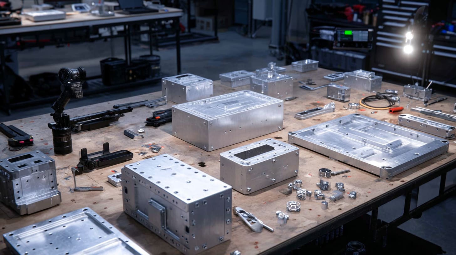
A good screw design does not happen by accident.
It usually comes from asking the right questions early, before the enclosure shape is frozen and before the team starts fighting over test results. I think this is where practical engineering earns its value. Not in grand theory, but in the small choices that keep a product stable, testable, and manufacturable.
I do not optimize screw design by staring at hardware catalogs. I optimize it by looking at frequency, seam behavior, contact surfaces, and the real life of the product.
That approach has saved more time for me than any late-stage fix ever has.
Define Frequency Range First
The first thing I want to know is what kind of electrical environment the enclosure is facing.
A product working at modest frequencies does not need the same seam discipline as one dealing with fast edges, sensitive circuits, or high-frequency sources. That is why I always want the frequency picture first. Without that, screw spacing decisions become guesswork dressed up as design.
| Question | Why I ask it |
|---|---|
| What frequencies matter most? | Determines seam sensitivity |
| Are there fast switching edges? | Raises EMI concern |
| Is the product sensitive to external noise too? | May require stronger shielding |
| What compliance target applies? | Sets design margin |
If the frequency story is serious, the seam deserves serious attention.
Control Contact Surfaces
I think this step gets less praise than it deserves.
A strong screw pattern on poor contact surfaces is still a weak design. So I pay close attention to where the real electrical path will sit. That may mean masking before anodizing, machining contact lands, or defining exact seam zones that must stay conductive.
This part should be intentional, not accidental.
| Surface control method | Why it helps |
|---|---|
| Bare metal contact zone | Improves conductivity |
| Defined mating area | Makes assembly more repeatable |
| Controlled finish removal | Reduces seam uncertainty |
| Clean assembly handling | Avoids contamination |
I trust designs more when the contact path is clearly planned, not left to chance.
Combine Screws with Supporting Solutions
The best results often come from combination, not purity.
A smart design may use moderate screw density, proper surface treatment, and a conductive gasket together. That usually gives more stable shielding than trying to force one single method to do everything.
I like balanced systems. They are more forgiving in production and more stable in use.
Here is a simple design mindset I often follow:
- Use screws to control spacing and pressure
- Use surface planning to protect conductivity
- Use gaskets or clips where seam demands are higher
- Keep the full seam behavior in mind, not just the hardware count
| Design approach | Likely outcome |
|---|---|
| Screws only, sparse layout | Risky |
| Many screws, poor surface plan | Wasteful and unreliable |
| Balanced fastening + surface control | Stronger |
| Balanced fastening + gasket support | Often best for demanding cases |
That is usually where a design starts feeling mature.
Prototype and Test Early
I do not like waiting until the final stage to discover that the seam was optimistic.
A prototype is not only for checking fit and appearance. It is for exposing bad assumptions while they are still cheap to fix. Even a simple early build can show whether the screw layout is too loose, the contact plan is weak, or the seam behaves worse than expected.
This is where small investments save big frustration.
| Early test focus | What it can reveal |
|---|---|
| Seam continuity check | Weak contact zones |
| Panel press test | Unsupported spans |
| Surface inspection | Coating mistakes |
| Early EMC review | Fastener layout weaknesses |
I would much rather adjust a screw pattern before production than explain later why the enclosure looked smart and behaved badly.
That is really what this whole topic comes down to. Not whether screws matter, but whether we are honest enough to treat them as part of the shielding system.
Conclusion
I think fewer screws create more problems because I have seen how often people judge enclosure seams by appearance, cost, or assembly speed and miss what the seam is doing electrically.
That is the core of my view.
I do not believe screw quantity is a small hardware choice in EMI shielding work. I believe it is part of the enclosure’s electrical design. A few missing screws may save a little money at the start. But if those missing screws lead to weak contact, longer leakage paths, unstable seam pressure, or unpredictable EMC results, that “saving” was never real.
The reason I think this way is simple. I have watched too many projects get trapped by details that looked harmless in drawings. A seam looked neat. A lid looked flat. The screw count looked efficient. Then the product entered testing, shipping, vibration, or real use, and the weakness finally showed itself.
So when I look at an EMI shielding enclosure, I do not ask only, “How many screws are there?” I ask better questions.
- Are they spaced well?
- Is the contact surface truly conductive?
- Will the seam stay stable over time?
- Is the design balanced, or just cheap?
- Did the team solve the real problem, or only the visible one?
That is why I would rather defend a thoughtful screw design than a clever-looking cost cut.
If you are working on a custom aluminum enclosure, a sheet metal housing, or an OEM shielding case, I think this is the kind of detail worth checking early, not after the test report gives you bad news. If you want, you can review your seam design, screw spacing, or contact plan before the enclosure goes too far into production. That one step can save a lot of wasted time later.
If your project needs a custom EMI shielding enclosure and you want a second set of eyes on the structure, contact details, or manufacturing approach, you can reach out to me. I care about these details because they decide whether an enclosure only looks good, or actually works.