Skip to content

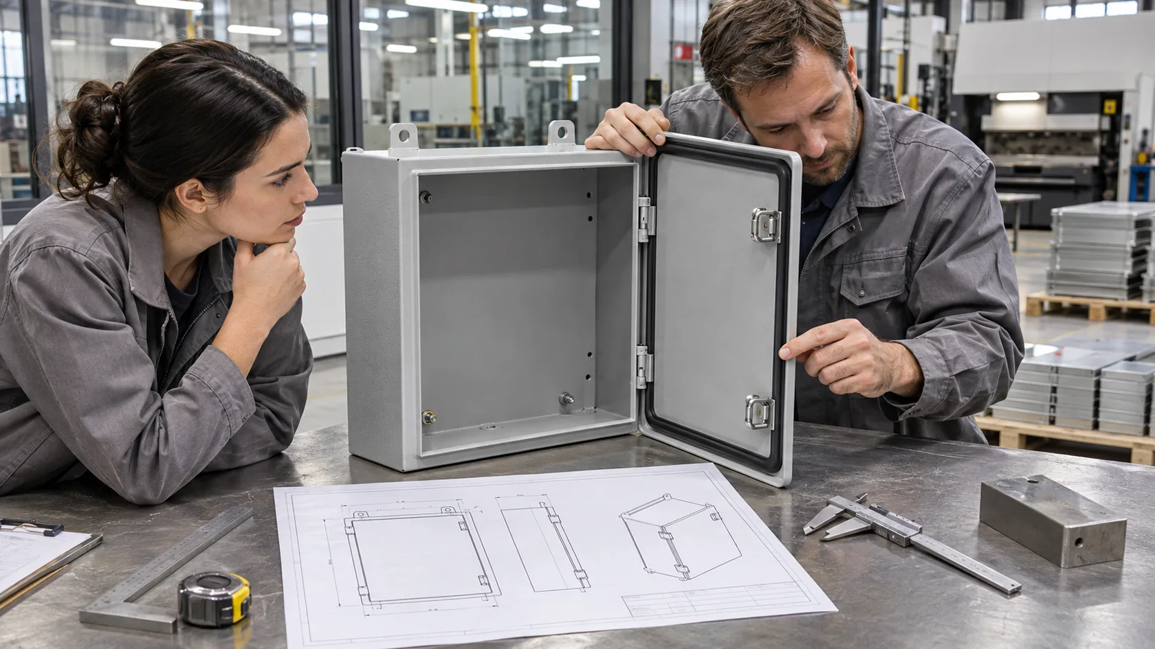
At quotation time, a higher NEMA Type can feel like the safe answer. The spec changes from Type 3 to 4X, or from 4X to 6P, and everyone expects risk to fall with the number. In custom enclosure work, that expectation is often where the real risk begins.
The label matters, but it answers a defined environmental question. It does not automatically correct a top-facing cable entry, a cover that flexes at one corner, an unsuitable gasket, trapped water behind a mounting flange, or heat that creates internal condensation. NEMA 250 is especially clear that its scope does not cover several internal or through-opening conditions, including condensation and corrosion.
I have seen teams pay for a stronger Type while leaving the water path unchanged. The useful first question is not “What is the highest rating we can buy?” It is “How can water, dust, heat, salt, or service work actually defeat this installed enclosure?”
That question makes the following selection work much more reliable.
A Higher NEMA Type Answers Only a Defined Exposure
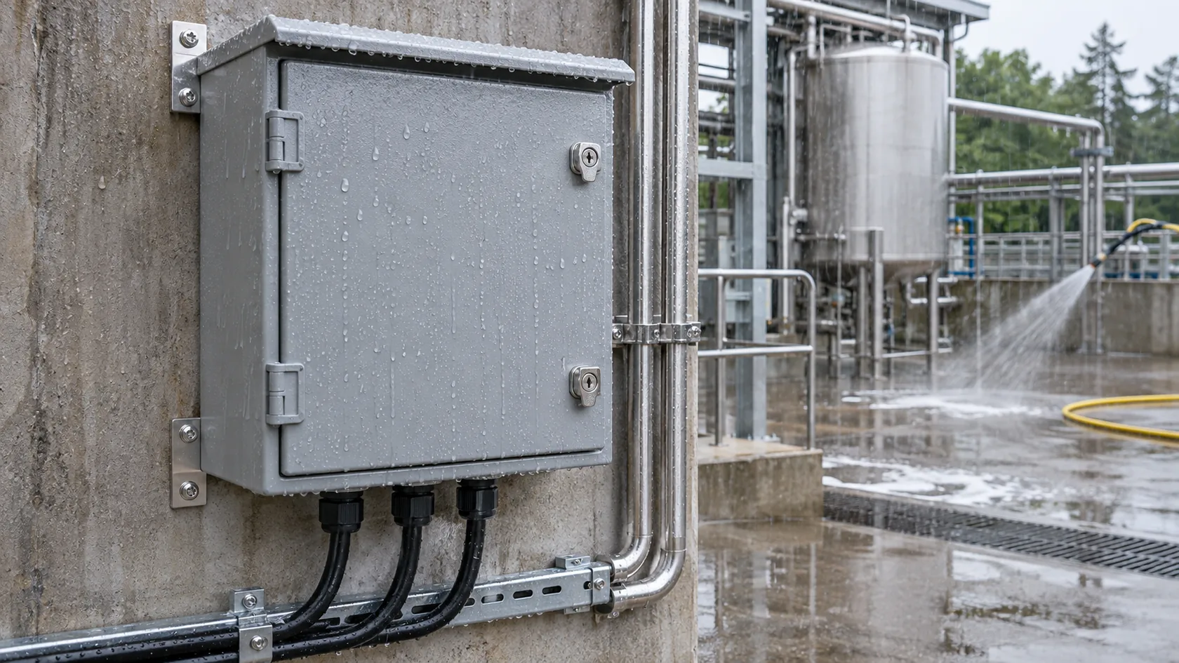
NEMA Types are application designations, not a universal ladder of protection. UL Solutions' enclosure Type table describes Type 3 for outdoor windblown dust, rain, sleet, and external ice formation; Type 4 adds splashing and hose-directed water; Type 4X adds corrosion; and Type 6P includes prolonged submersion at a limited depth. Those are different exposure problems, not simply successive upgrades.
Define the water before choosing the label
| Site condition | Details that change the enclosure decision |
|---|---|
| Outdoor weather | Rain direction, wind, dust, ice, UV, roof runoff, mounting angle, and drainage |
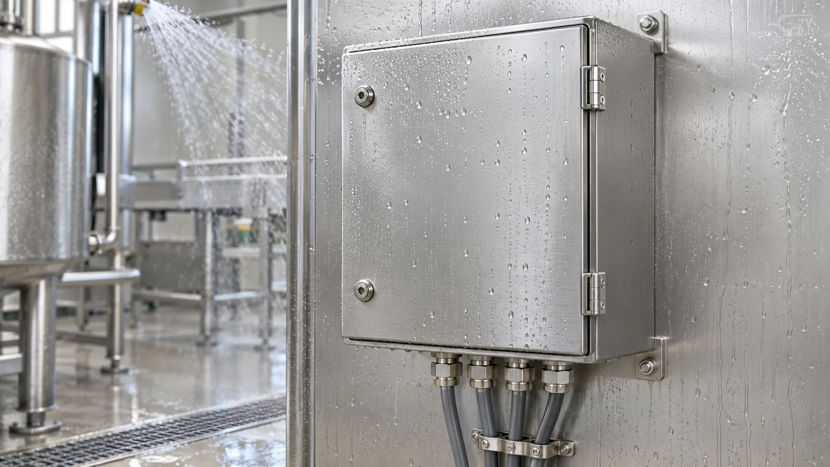
| Washdown | Liquid, spray direction, pressure, distance, frequency, temperature, and cleaning chemistry |
| Corrosive exposure | Salt, vapor, cleaner residue, crevices, cut edges, hardware, and maintenance access |
| Flooding or immersion | Fluid, depth, duration, temperature, pressure changes, cable route, and recovery procedure |
A rooftop transmitter with normal rain may not need the same solution as a cabinet repeatedly sprayed with alkaline cleaner. A control box beside a tidal area may need corrosion design more urgently than a nominally higher water designation. A below-grade sensor enclosure may need an immersion condition defined in engineering terms, not just the word “waterproof.”
My practical rule is to spend time describing the exposure before spending money on the label. If the exposure has not changed, a higher Type can become an expensive confirmation of the wrong design assumption.
With the threat defined, the complete boundary becomes visible.
The Installed Assembly Usually Sets the Limit
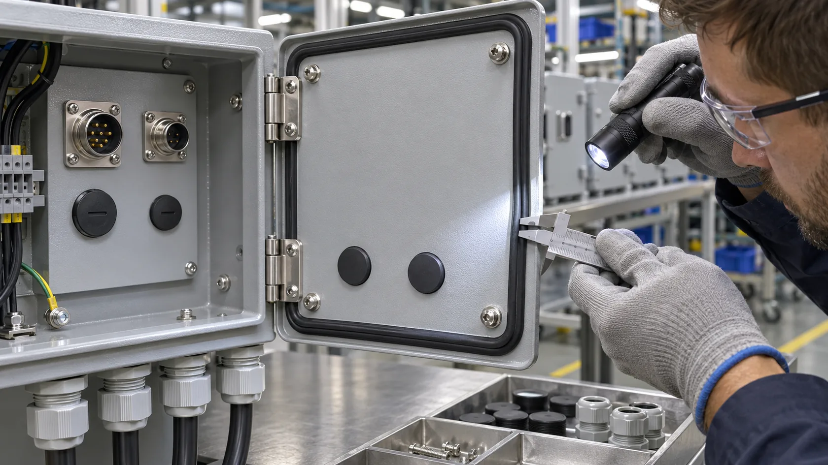
A bare cabinet cannot carry the environmental result for a finished product by itself. The lid joint, gasket, fastener pattern, cable glands, connectors, display window, vent, buttons, mounting interface, and every unused opening all become part of the boundary. A rated component also has to be compatible with its actual cable size, torque, wall thickness, thread engagement, orientation, and service access.
Review every penetration in its working position
- Put the actual cable outside diameter and entry direction on the drawing.
- Confirm a gland or plug is suitable for the installed wall thickness, hole, thread, and torque access.
- Route cables downward where practical and account for drip paths and strain relief.
- Check that connectors, windows, vents, pushbuttons, hinges, and field-installed accessories fit the target condition.
- Close unused holes with compatible plugs; do not treat future openings as a field decision.
OSHA’s wet-location requirements also focus on installation: enclosures in damp or wet locations must be installed to prevent moisture or water from entering and accumulating within them, and weatherproof enclosures are required in wet locations. That installation principle is more useful than assuming the shell alone does the job.
I would rather use a simpler shell with a fully controlled entry system than quote a higher Type around unspecified cable holes. A small interface error is often more decisive than the material cost of the cabinet.
Once those interfaces are controlled, the next trade-off is usually temperature and moisture inside the box.
More Sealing Can Create a Different Failure Mode

Sealing reduces unintended airflow, which can be necessary for the selected environmental condition. It can also make heat rejection and pressure equalization harder. A sun-exposed enclosure with internal power electronics can cycle from warm to cool while outside humidity changes; if the thermal path and moisture behavior are ignored, water may appear inside even though no external seam visibly leaks.
Design the heat path and the seal path together
| Design choice | Risk if reviewed alone | What to resolve together |
|---|---|---|
| Tighter gasketed cover | Less accidental airflow but more trapped heat | Heat load, permitted component temperature, cover area, mounting surface, and conduction path |
| Pressure-equalization vent | May help with pressure changes | Environmental target, installed orientation, contamination exposure, and maintenance |
| Exterior sun exposure | Raises shell and internal temperatures | Finish color, solar load, internal dissipation, shading, and ventilation strategy |
| Drain or low point | Can help control standing moisture in some designs | Water path, target Type, ingress risk, mounting angle, and service procedure |
The solution is not to drill a late vent into a sealed design, and it is not to seal every opening without checking the heat source. A vent, drain, or heat sink changes the boundary and needs to be reviewed as part of it. The same is true of condensation-control measures: their suitability depends on the actual enclosure, climate, and electronics.
In factory reviews, the costly surprise is often a good gasket combined with an unplanned hot power supply. I prefer to see thermal inputs before the sealing detail is frozen, not after a pilot unit sweats during a temperature cycle.
That thermal review also prevents material and finish choices from being treated as a shortcut.
Corrosion Protection Is a Separate Design Decision

Type 4X adds corrosion protection to its stated environmental intent, but “corrosion resistant” still needs a project definition. Aluminum, coated steel, stainless steel, fiberglass, and engineered polymers can each be sensible choices in the right geometry and exposure. The shell material is only one part of the system; fasteners, hinges, gland plates, cut edges, weld areas, finish damage, trapped deposits, and dissimilar-metal contacts can decide service life.
Write the corrosive condition into the RFQ
For a coastal installation, name the salt exposure, standing-water risk, drainage, and maintenance interval. For a processing area, provide the cleaner or chemical, concentration where known, application temperature, frequency, and where residue collects. For any coating or anodizing, specify the finish system and the edge, scratch, and electrical-interface details that still need protection.
An enclosure can look excellent at sample approval and still corrode at a latch, unsealed cut edge, or unprotected bonding point once it sees real service. UL’s certification guidance treats enclosure accessories as relevant to Type or IP-rated systems for a reason: the accessories are part of the performance boundary.
I do not accept “make it 4X” as a material specification. A clear exposure statement is cheaper than choosing stainless steel by habit, then discovering that cleaner residue and trapped water are attacking the hardware instead.
The same care is needed when electrical continuity or serviceability share the enclosure boundary.
Grounding, EMC, and Service Must Fit the Weatherproof Plan
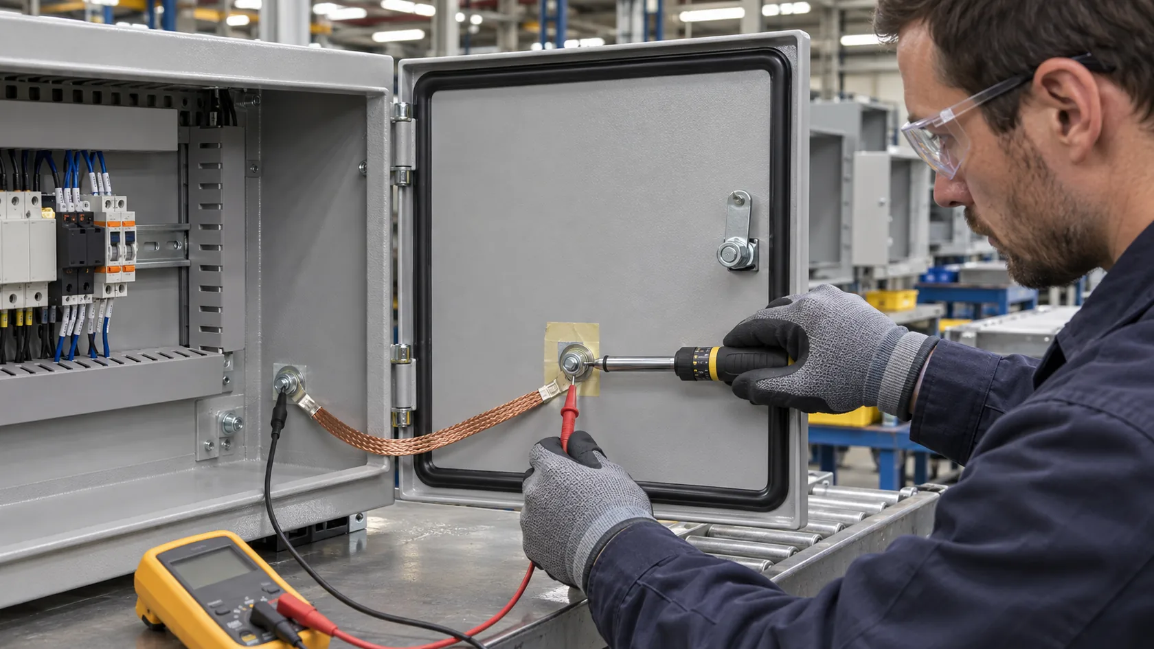
Weatherproof construction can conflict with other requirements if each is handled in isolation. Powder coating, anodizing, or other protective finishes may interrupt an intended bonding or EMC path. A gasket can create a reliable water seal yet be electrically insulating. Service doors, removable covers, external antennas, and field wiring need both a weatherproof interface and a repeatable way for a technician to restore it after opening.
Do not hide electrical interfaces behind a finish note
- Identify the grounding and bonding points before coating, anodizing, or assembly.
- Design a controlled conductive interface where it is required, then protect adjacent areas from corrosion.
- Specify hardware, washers, torque, and masking or surface preparation where those affect continuity.
- Make a resealing and inspection instruction part of the service procedure for covers, gaskets, glands, and plugs.
For electrical equipment, continuity requirements are not automatically met because a metal cabinet is present. OSHA states that metal raceways, armor, and enclosures for conductors must be joined to provide effective electrical continuity. The requirement is a useful reminder that environmental protection and electrical bonding both need intentional interfaces.
From a manufacturing viewpoint, a sealed cover that is opened once in the field can become the weakest version of the design. I favor simple features that make correct reassembly obvious—clear gasket seating, protected threads, accessible torque points, and no hidden “special touch” required from the installer.
Those features belong in validation, not only in an assembly worker’s memory.
Validate the Production-Intent Configuration
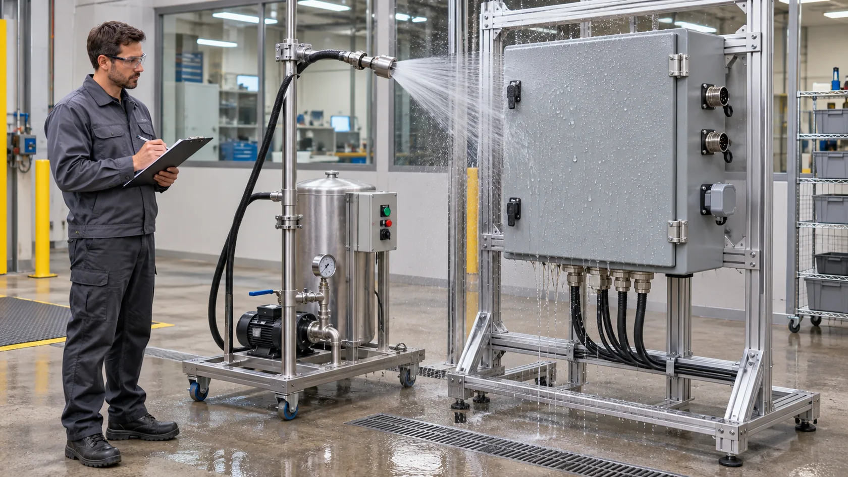
Testing a clean, empty sample can be useful for development, but it does not prove the finished configuration. The production-intent sample should include the actual cover, gasket, fastener pattern, latches, cable entries, connectors, windows, vents, internal loads, mounting orientation, and fitted plugs that the customer will receive. If a component or layout changes, assess whether the environmental result must be validated again.
Keep rating language, test method, and acceptance criteria connected
IEC 60529 is the international standard for degrees of protection provided by enclosures using the IP Code. It should not be treated as a loose one-to-one conversion chart for NEMA Types. The water exposure, the specified standard, the product configuration, and the applicable market or approval route should all be stated separately.
For a custom project, agree in writing on the sample configuration, test basis, orientation, inspection method, acceptance criteria, records to be supplied, and which production changes trigger review. This does not turn an unlisted custom housing into a certification claim; it creates a disciplined way to make the buyer’s required performance testable.
I put more confidence in a modest, specific validation plan than in a broad “highest rating” request with no sample definition. It gives both buyer and factory a common reference when a new cable, connector, or late hole is proposed.
That discipline turns an RFQ into a useful risk-control document.
An RFQ Checklist That Reduces Real Risk

The most reliable enclosure quote gives the supplier enough information to check the real failure paths. A rating should be included, but it should not carry the entire requirement by itself.
- State the exact requested NEMA Type, applicable market, and approval or listing expectation.
- Describe rain, dust, washdown, chemicals, salt, UV, temperature range, mounting orientation, and any flood or immersion condition.
- Provide a drawing that identifies all openings, lid or door joints, mounting faces, drains, vents, and service access.
- List every cable, conduit, connector, window, button, antenna, gland, plug, and accessory, including cable outside diameters and entry directions.
- Define shell material, finish, gasket, hardware, grounding/EMC interfaces, and corrosion-sensitive contacts.
- State internal heat load, heat-sensitive components, sun exposure, and any required thermal path.
- Agree on the production-intent sample, test method, acceptance criteria, and change-control checkpoints.
This checklist makes comparison fairer between suppliers. It also reveals when the design needs a drainage change, a different cover geometry, a revised latch pattern, a controlled cable entry, or a conversation about thermal limits before material is cut.
In my experience, this is the point where a higher NEMA request becomes either justified or unnecessary. The result is not a lower standard; it is a more honest one.
With that information, a Type becomes a defensible part of the design instead of a substitute for it.
Conclusion

A higher NEMA Type lowers risk only when it matches a real additional exposure and the finished enclosure preserves the required boundary. It will not repair a poor cable route, trapped water, an incompatible gasket, unmanaged condensation, corrosion-prone detail, interrupted ground path, or a field-service step that destroys the seal.
After years of making custom enclosures, I find the safest approach is usually the least complicated Type that honestly fits the exposure, supported by an installed-system review and a production-intent validation plan. If you are specifying a weatherproof enclosure, send MaidaTech the drawing, mounting direction, entry schedule, water or cleaning condition, corrosion details, and internal heat load. We can review the practical seal path before the rating becomes an expensive assumption.