Skip to content


Powder coating often enters an enclosure project as a finish decision: choose the colour, texture, gloss, and corrosion system. The electrical consequence tends to arrive later, when a technician fits an earth lug to a painted wall or closes a coated door that is meant to be bonded. At that point, a metal enclosure may be mechanically complete but electrically divided by its own finish.
For custom enclosures, I treat powder coating as part of the electrical interface stack-up. It is normally insulating, so every connection that must be conductive needs a deliberate route, surface condition, hardware stack, and inspection method. The qualified product designer and compliance team must still define the applicable safety, installation, fault-current, and EMC requirements. Our factory role is to turn that intent into details that coating and assembly can repeat.
The useful question is not simply, “How do we ground this box?” It is which parts must connect, for what purpose, and through what physical method after the coating line has done its work.
Start With the Electrical Job, Not the Hardware
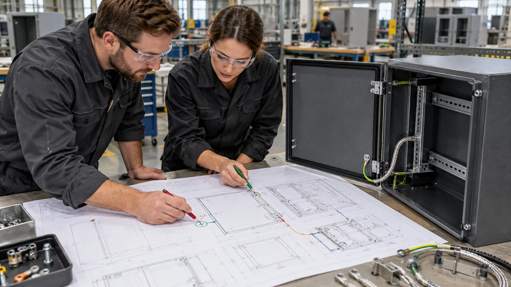
One enclosure can need several different connections
Grounding establishes a defined reference or protective path; bonding joins conductive parts so they remain at the electrical relationship the design requires. The methods can overlap, but they are not interchangeable. OSHA describes equipment grounding as a permanent, continuous path for fault current, while UL Solutions' grounding and bonding guidance stresses the need for continuity and capacity where metal enclosures serve that function.
Before choosing a stud, serrated washer, braid, gasket, or spring finger, I ask the team to create a short interface map:
| Interface | Possible job | Suitable method family | What must be defined |
|---|---|---|---|
| Protective-earth terminal to chassis | Product-defined protective path | Dedicated terminal on a prepared land | Terminal, hardware stack, finish boundary, access, verification |
| Fixed panel or subplate to chassis | Defined chassis or low-frequency bond | Direct fastener joint | Mating surfaces, hardware, torque, corrosion control |
| Door or removable cover | Bond after movement or removal | Flexible jumper or controlled contact | Flex life, route, attachment, service sequence |
| Lid seam or aperture | EMC shielding behavior | Conductive gasket, spring contacts, controlled seam | Geometry, compression, spacing, finish, EMC validation |
| Cable shield or connector shell | Shield termination | Defined connector or clamp interface | Flange condition, cable-entry geometry, system EMC design |
This small table keeps the quotation honest. In my experience, the costly error is buying one “grounding solution” and expecting it to cover safety, a moving door, and an RF seam at the same time.
With the job named, the main protective connection can be designed as a real interface instead of a ground symbol added near the end.
Method 1: Dedicated Protective-Earth Point
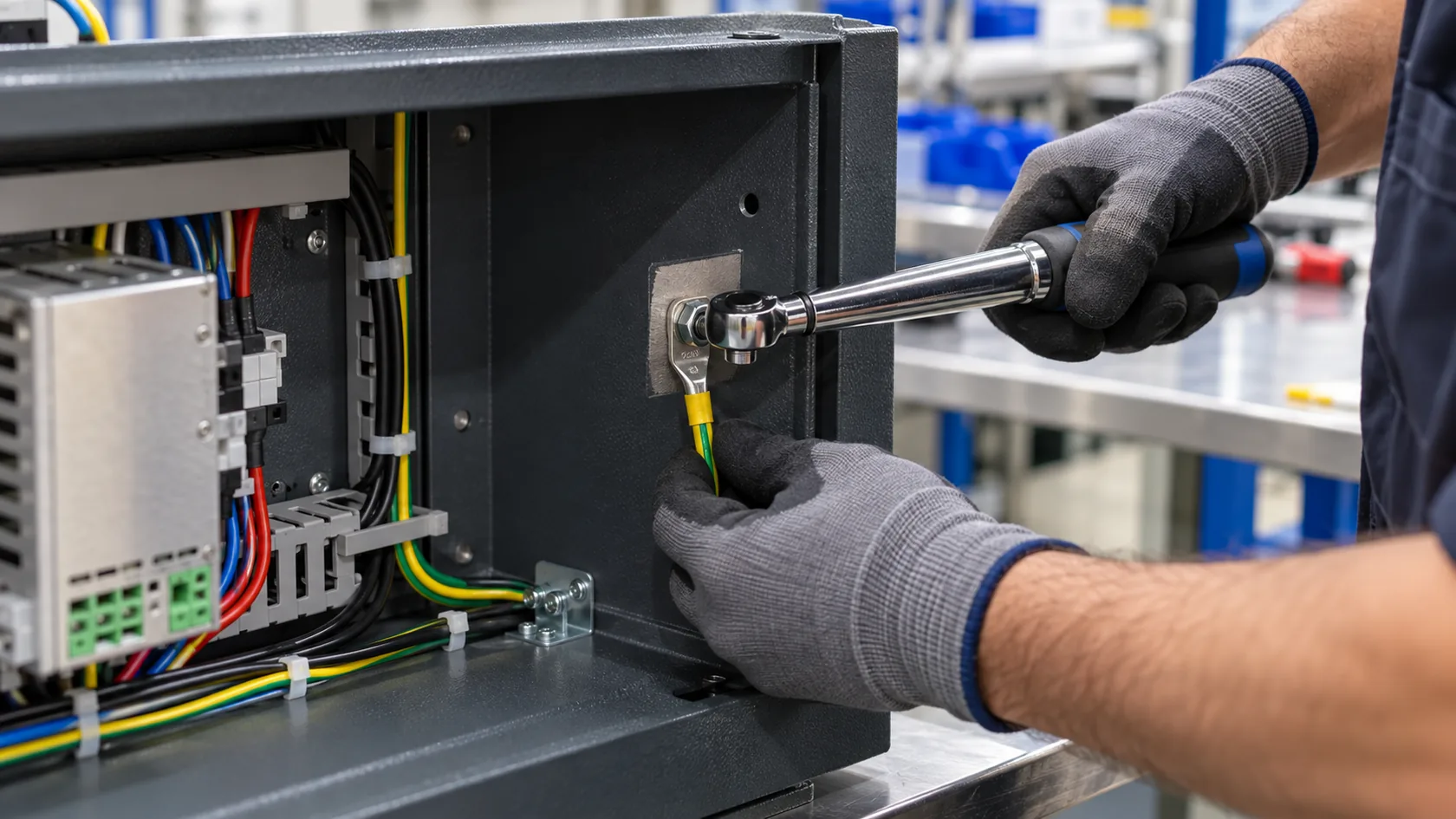
Make the chassis connection deliberate and accessible
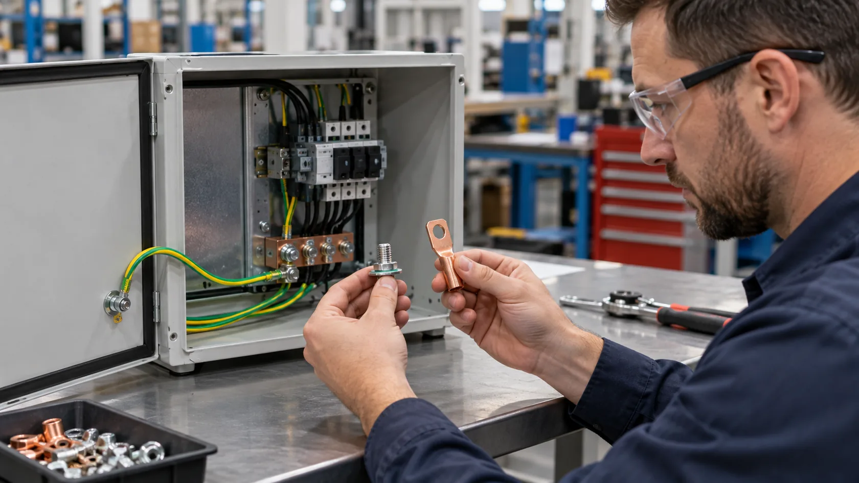
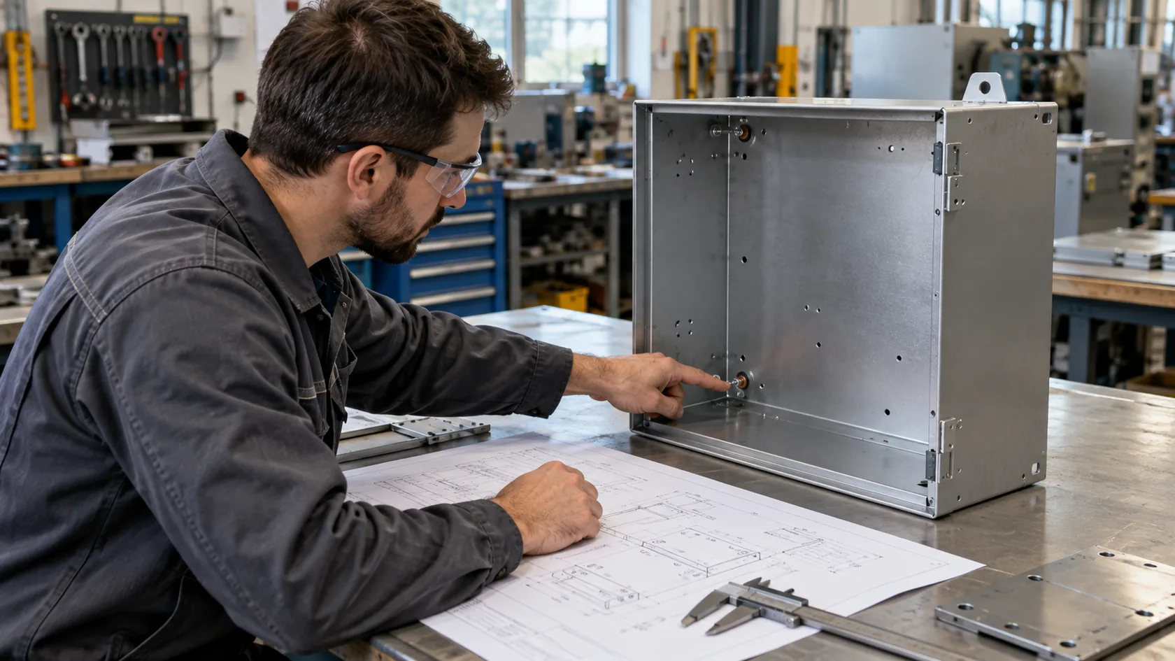
A dedicated protective-earth point is usually the clearest enclosure-side method when the released electrical design requires one. It commonly uses a stud, threaded point, or approved terminal arrangement on the structural chassis, with a limited uncoated contact land or other specified conductive treatment. The lug, washers, locking feature, terminal orientation, tool clearance, marking, and conductor route should all be part of that released arrangement.
The point is not to leave a large unfinished patch. It is to define a small, protected area where the approved hardware reaches the base metal or approved conductive surface consistently. The OSHA grounding-path guidance is a useful principle here: a path that can be loosened, corroded, or interrupted over its life is not made reliable by a green-yellow conductor alone.
For a powder-coated enclosure, I prefer masking or another approved finish boundary shown on the drawing over telling an assembler to scrape paint “as needed.” A random scraped area can damage corrosion protection, vary with operator technique, and be difficult to inspect after the terminal is fitted.
That controlled chassis point then gives fixed internal parts a known place to join when their design requires it.
Method 2: Fixed Panel and Internal Chassis Bonds
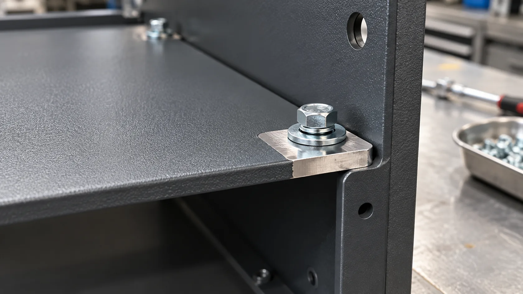
Use direct joints only where their contact condition is controlled
Fixed mounting plates, chassis sections, and rigid brackets can often use a direct fastener joint. This is compact and economical when the design controls the metal-to-metal path. The drawing should identify the mating surfaces, finish exclusion or approved conductive treatment, hardware stack-up, tightening process, and any locking approach needed for the actual environment.
Serrated hardware may be part of an approved assembly, but it is not a universal substitute for the interface design. Its effect depends on the material, coating thickness, washer geometry, clamp load, service history, and the requirement it is expected to meet. It can also create a local finish breach that needs corrosion review.
| Direct-joint questionWhy it matters after powder coating | |
|---|---|
| Is the contact land identified? | A painted flange or fastener hole may isolate the parts completely. |
| Is the joint rigid and stable? | Vibration, thermal cycling, or repeated disassembly can change contact pressure. |
| Is the hardware sequence controlled? | An omitted washer, reversed lug, or wrong fastener can change the intended path. |
| Is corrosion considered? | A bare interface can degrade if exposed to moisture, salts, cleaners, or incompatible metals. |
I do not assume every screw joining two metal parts is a bond. If that screw joint has an electrical job, I want its surfaces and assembly instruction to show that job plainly.
Rigid joints work well where the parts stay together; moving or frequently removed parts deserve a method that acknowledges their movement.
Method 3: Doors, Covers, and Other Moving Parts
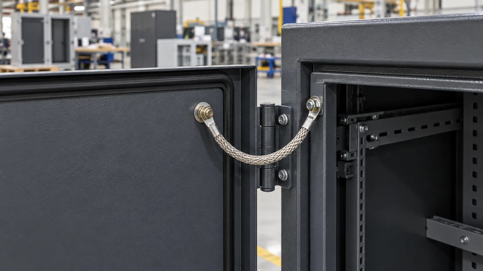
Give the moving part its own defined path
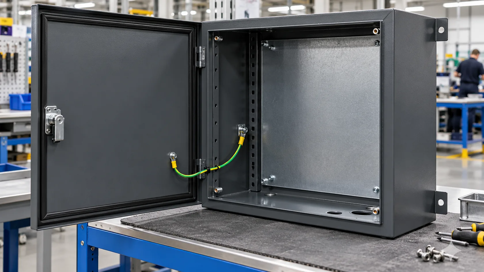
A door, lid, or removable panel can be mechanically secure while the paint, hinges, pins, lubricant, wear, or mounting sequence leaves its electrical relationship uncertain. When the approved design requires that part to be bonded, a short flexible bonding jumper is often the more transparent method. It makes the intended path visible and avoids relying on a hinge as an undocumented electrical contact.
The jumper still needs engineering. Its conductor type, width or cross-section, length, attachment points, bend radius, routing, strain relief, clearance from sharp edges, and allowance for the full opening movement should follow the product requirements. It also has to remain accessible enough for assembly and service without becoming a snag point for wiring or a reason a technician removes it.
I have seen a neat braid fail the practical test because it was just a little too short: it pulled tight at the last part of the door swing and was later replaced with whatever wire was nearby. The better drawing shows the open position, attachment points, and the approved replacement information.
The same discipline applies to a seal or seam that is expected to perform an EMC function, but its physics are different from a protective bond.
Method 4: EMC Seams and Conductive Interfaces
Do not turn a DC check into an EMC claim
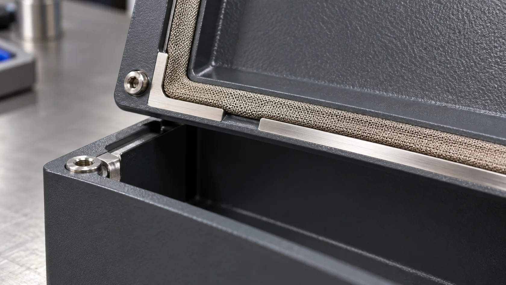
Where a seam is part of the shielding design, conductive gaskets or spring contacts may be appropriate. They are selected around the actual seam geometry, aperture layout, contact spacing, compression range, fastener arrangement, coating boundary, corrosion environment, and service needs. A long painted joint with one bare screw location may show some DC continuity yet still be a poor substitute for a controlled shielding seam.
The European Commission's EMC guidance places responsibility at the equipment level. For enclosure buyers, that means a conductive gasket is an interface component, not a finished-compliance label. The completed apparatus, cable layout, electronics, openings, and applicable test plan determine the meaningful EMC result.
NASA's Electrical Bonding Design Guide is also useful for its design discipline: bonding areas and the associated requirement should be communicated on engineering drawings rather than inferred at assembly.
When I review an EMC seam, I look first for a coherent path around the opening and then ask how it will survive coating, compression set, corrosion, and a service technician opening the cover. That is more reliable than choosing a conductive material from a catalogue in isolation.
Cable entries need the same function-first treatment because a connector shell is not automatically an extension of either a PE path or a shielding seam.
Method 5: Cable Shields and Connector-Shell Interfaces
Define the cable interface separately from the enclosure earth point
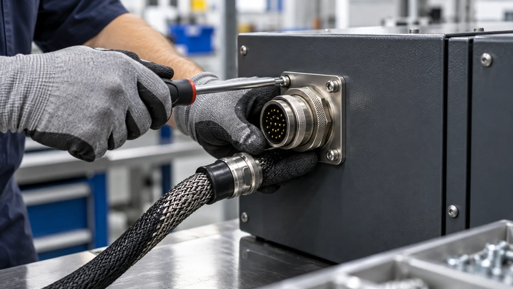
A cable shield, connector shell, or gland body may need a defined chassis or EMC interface, depending on the system design. The connector flange, mounting hardware, gasket, panel coating, cable clamp, and internal termination all affect that interface. A painted panel can isolate a metal connector shell; a generic grounding lead can be the wrong geometry for the required shielding behavior.
This is why I keep cable-entry notes separate from the PE-terminal note. The electrical designer needs to state the intended function and termination approach, while the enclosure drawing needs to preserve the necessary physical conditions: approved surface treatment, opening size, wall thickness, gasket and hardware arrangement, clearance, and access for installation.
For outdoor or washdown equipment, the entry also has to maintain its required ingress protection in the installed orientation. Gasket compression, cable diameter range, torque, drainage, and connector selection are installed-system details. A conductive path that compromises the seal is not a good trade.
Once the methods are chosen, production control determines whether the second hundred enclosure has the same interfaces as the first one.
Make the Method Survive Coating, Corrosion, and Service
Control the bond through the whole factory sequence
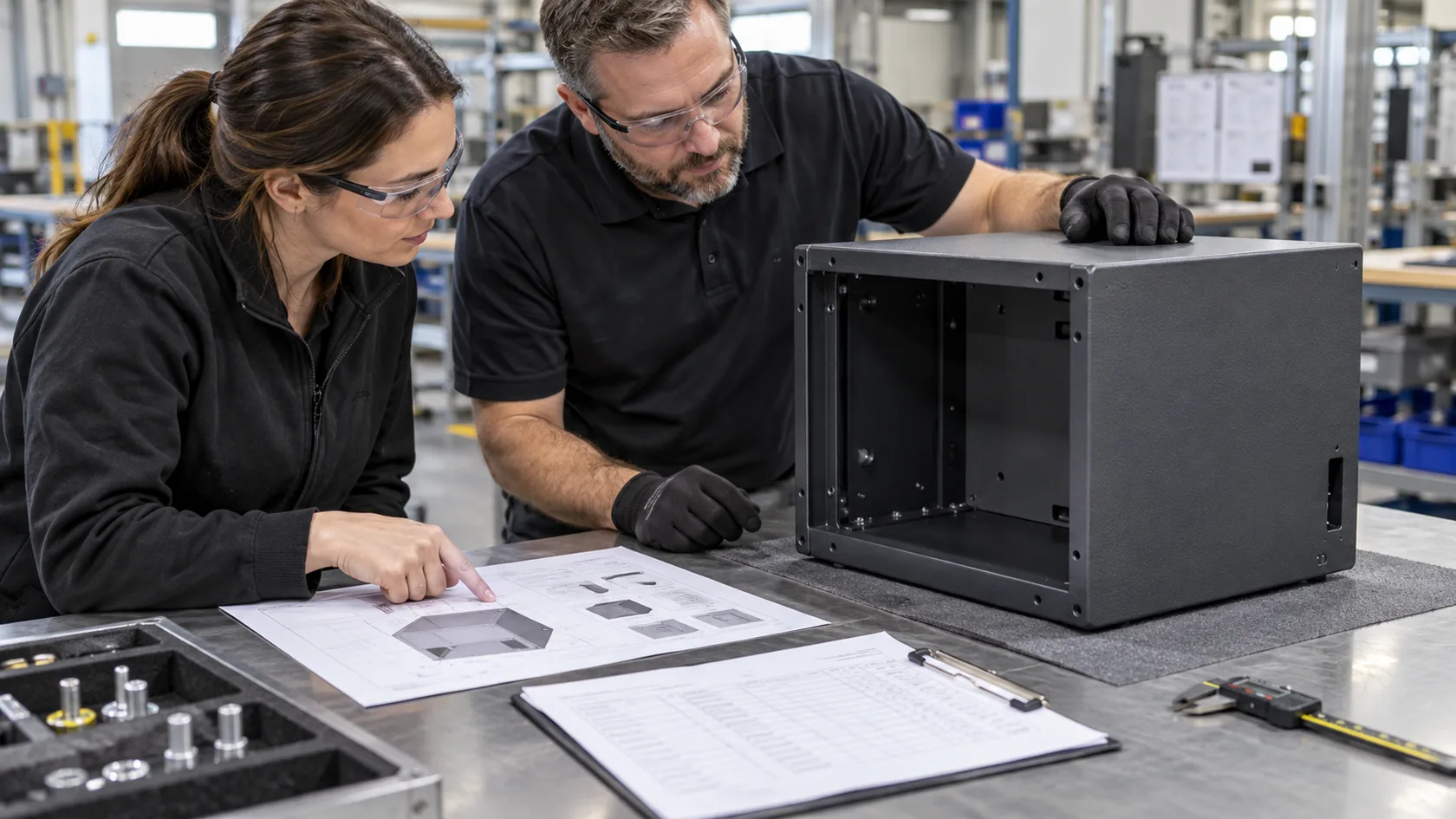
The strongest practical document for this work is a finish/bond map. It lists each required interface, the function, mating parts, permitted surface condition, hardware, corrosion protection, assembly instruction, and verification evidence. It gives fabrication, coating, assembly, quality, and service teams one common reference.
| Production control | Practical evidence |
|---|---|
| Contact-land boundary | Drawing callout, masked-area dimension, approved treatment, visual criterion |
| Hardware stack-up | Bill of materials, assembly image, torque or process requirement when specified |
| Moving-part jumper | Part number, routing view, open-position clearance, attachment inspection |
| EMC seam | Gasket or spring-contact specification, compression and fastener controls, finished-assembly EMC plan |
| Ongoing condition | Product-defined continuity or other verification record, corrosion and service observations |
I would not invent one resistance limit for every enclosure. The responsible product and compliance team should define the instrument, method, test current where applicable, probe points, acceptance criterion, assembly state, and sampling plan. A simple continuity reading can be a valuable manufacturing check, but it does not by itself prove fault-current capability, shielding effectiveness, or finished-apparatus compliance.
Coating is often the last visible process, so it is tempting to treat it as the end of the story. In a good enclosure program, the finish plan is already linked to the electrical interfaces before the first part reaches the powder booth.
Conclusion

Powder-coated enclosures need more than a generic grounding note. A dedicated protective-earth point, a fixed panel joint, a door jumper, an EMC seam, and a cable-shield interface each have different jobs and may need different physical methods. The recurring lesson from factory work is that the method becomes dependable only when its surface condition, hardware, movement, corrosion exposure, assembly, and verification are all specified together.
I would start a new project by marking every required conductive relationship directly on the drawing: what it connects, what it is intended to do, where coating must stop or change, and how the completed assembly will be checked. If you have a powder-coated enclosure drawing, a brief review of those interfaces before tooling or finishing approval can prevent a surprisingly expensive late correction.