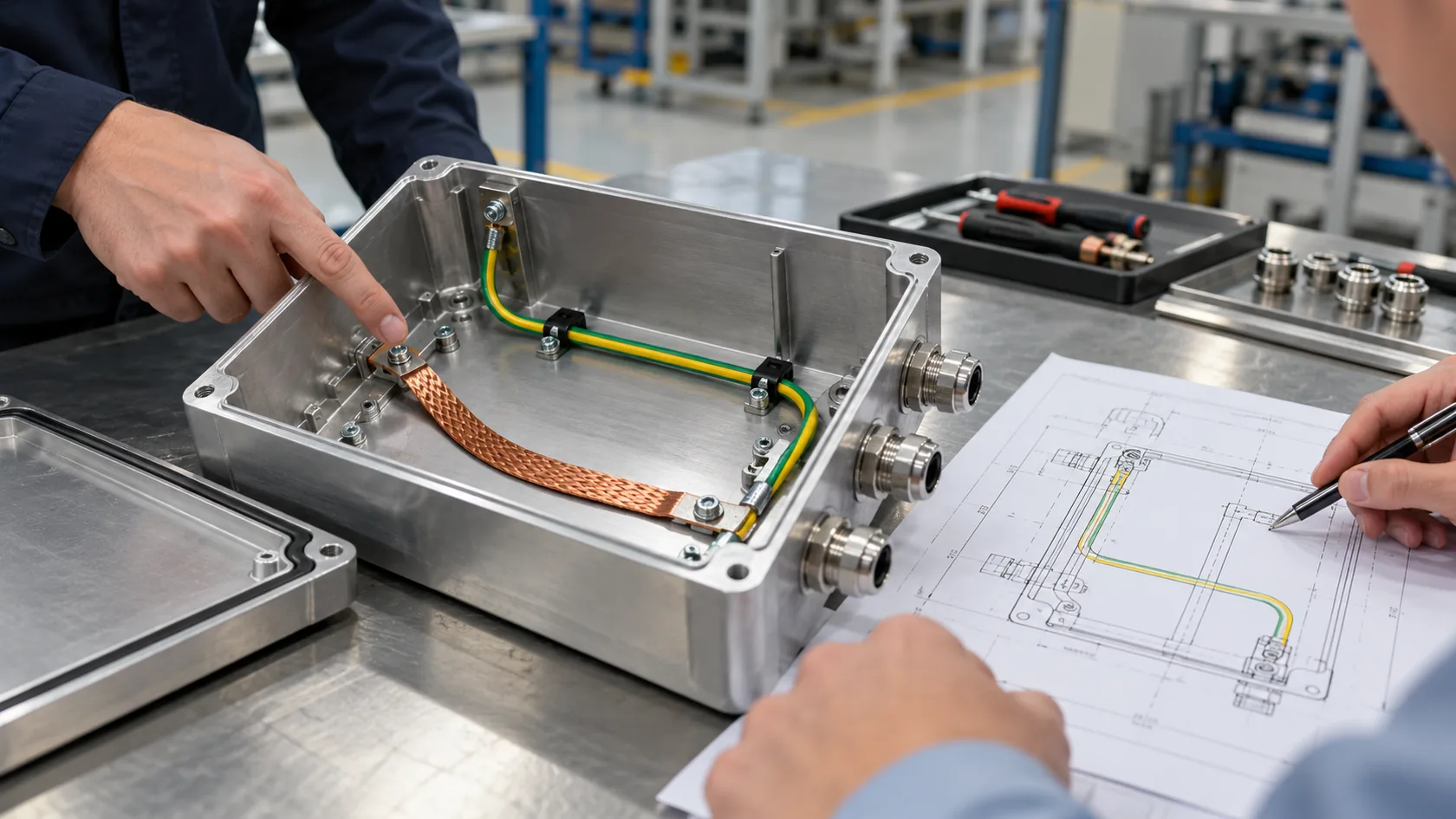
Skip to content

An aluminum enclosure can look electrically complete on a drawing: a lid, six screws, a ground symbol, and a powder-coated finish. Then the first article arrives and the lid is insulated by coating, the screw heads only touch paint, and a service technician has no reliable path across the removable joint. The materials were all “metal,” but the interface was never designed as a bond.
This article is about choosing and controlling the physical bonding method—screws, straps, conductive gaskets, spring contacts, and prepared contact lands. It does not replace the electrical designer’s safety, protective-earth, or EMC design. It helps buyers turn that design intent into enclosure details a factory can make repeatedly.
In my experience, the best method is rarely the one with the most impressive name. It is the one that still works after coating, assembly, shipping, service, and the real environment have had their say.
Start With the Job the Bond Must Do
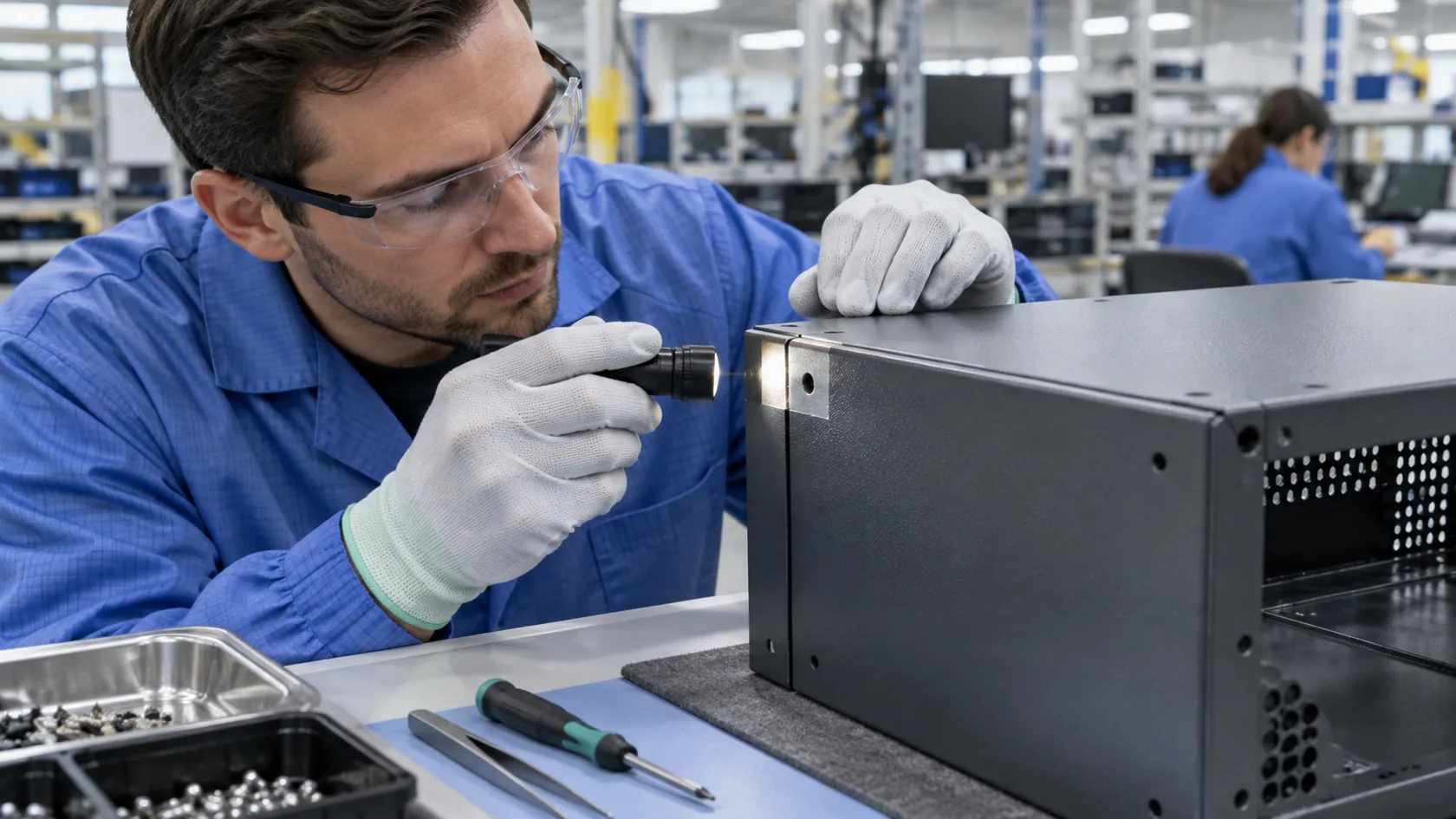
“Bond the cover” is not enough instruction. A connection intended to keep removable conductive parts at a controlled potential, a protective path, and a high-frequency shielding seam can demand very different geometry and verification. OSHA distinguishes bonding from equipment grounding and notes that metal parts used in a grounding path must be effectively bonded for continuity and fault-current capacity where required (OSHA 1910.305).
Before selecting hardware, settle four points:
- Which two parts must connect, and whether the joint is permanent or routinely opened
- Whether the concern is safety, static control, low-frequency continuity, EMC shielding, or more than one of these
- The exposure to vibration, moisture, salt, cleaning chemicals, and service wear
- The specified verification method and the responsible electrical/compliance owner
I ask for that function first because the same braided strap can be sensible on a service door and entirely beside the point for a long shielding seam. A generic “grounding accessory” line on a quotation hides that difference.
Screws and Direct Metal-to-Metal Joints
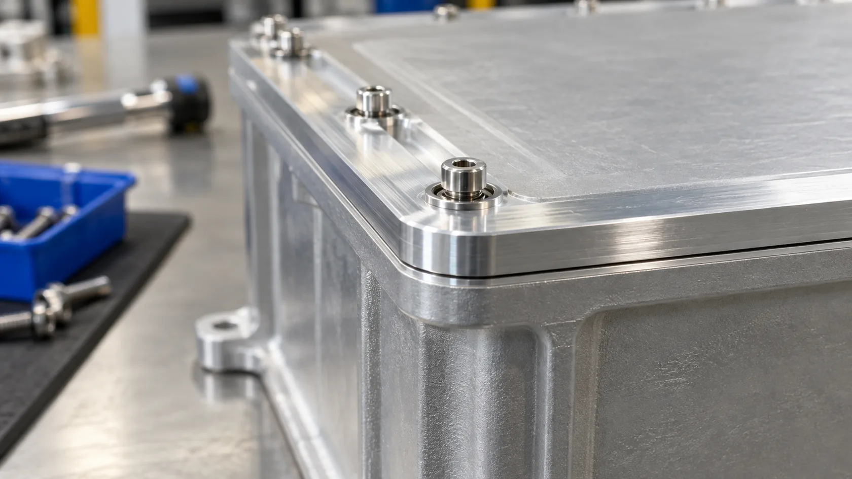
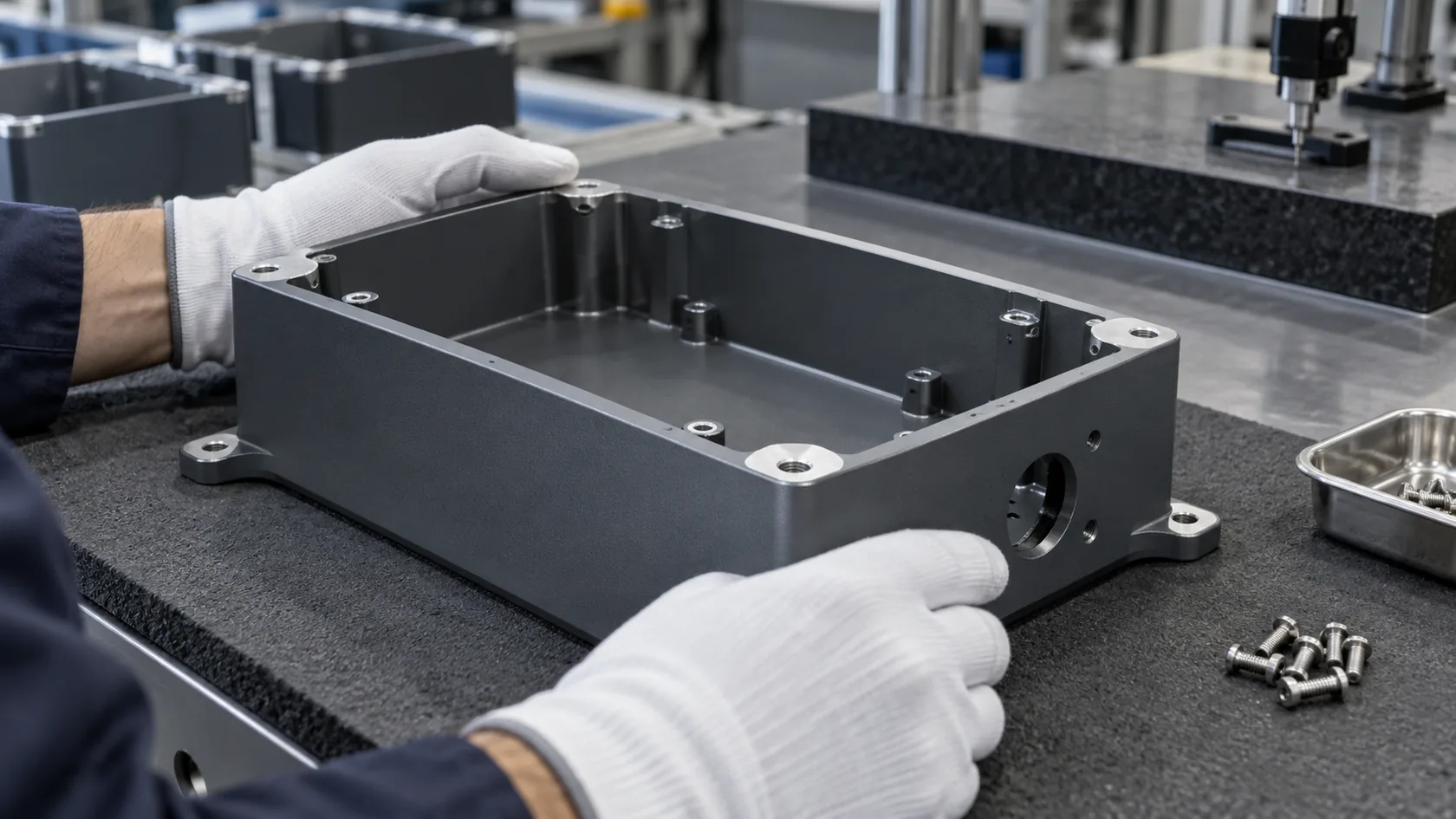
Bolted joints are compact, low-cost, and often the cleanest bonding method when the mating faces and assembly controls are designed for it. They work best when the intended contact is deliberate: enough clamping points, stable overlap, clean compatible surfaces, and a fastening process that is not defeated by a cosmetic finish.
What makes a screw joint dependable
- Define contact lands or approved conductive treatment rather than assuming paint will be displaced
- Keep the joint rigid enough that vibration and repeated opening do not relax it
- Specify hardware stack-up, locking approach, and torque through the approved design
- Protect exposed contact regions from the actual corrosion environment
OSHA’s guidance is unusually plain on this point: nonconductive coatings should be removed at contact surfaces when they would prevent effective continuity, unless fittings are designed to avoid that need (OSHA 1910.305). That is not a reason to scratch every finished surface in production; it is a reason to control exactly where the electrical interface is made.
I like screw bonding for a fixed, well-supported panel. I become cautious when the only intended contact is a few painted lid screws that a customer will remove every month.
Serrated Hardware and Bonding Washers
Serrated washers and similar hardware can help establish contact through selected surface treatments, but they are not a magic cure for every finish stack. Their teeth, plating, substrate thickness, tightening load, corrosion behavior, and placement all matter. A washer that bites successfully in a sample can be inconsistent if coating thickness varies or the assembly operator changes the hardware order.
Use this approach when the approved design has a defined stack-up and enough local stiffness. Avoid treating it as a substitute for a mask, a controlled land, or a separate jumper where the joint moves or needs durable service access.
From a production view, the risk is usually not the washer itself. It is an apparently harmless substitution—a different head style, coating, or washer orientation—that no one thought needed electrical review.
Braided Straps and Flexible Bonding Jumpers
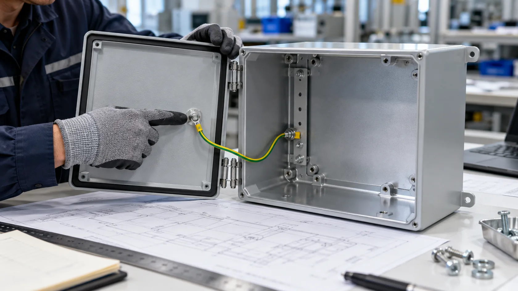
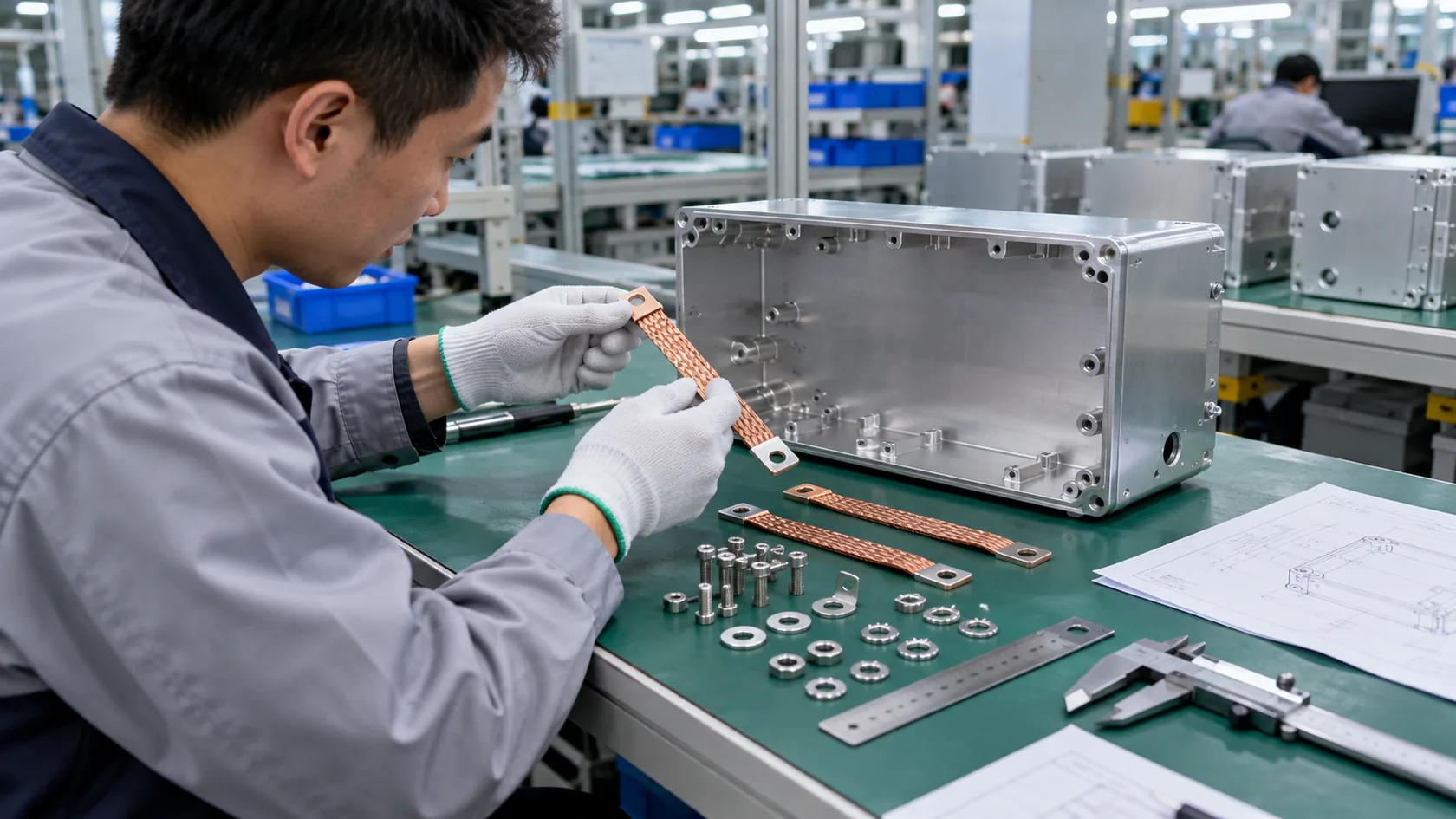
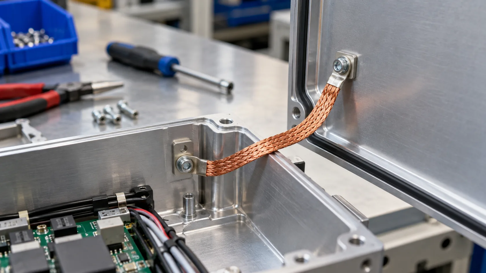
A flexible strap gives a dedicated path across a door, removable lid, hinged panel, or vibration-prone assembly. It is often easier to inspect than hoping hinges or closure screws remain electrically reliable. But a strap only performs as well as its terminals, bend allowance, routing, corrosion protection, and fatigue life permit.
Design the strap as an assembly, not a loose accessory
Give the strap clear endpoints, protected routing, service slack that does not snag, and fastening locations with tool access. Do not place it where a sharp edge, repeated lid rotation, or trapped gasket will damage it. Its size and connection design must come from the product’s electrical requirement; the enclosure factory should not invent that specification.
For a service lid, I generally prefer a visible, protected strap to an invisible assumption about hinge continuity. It costs a little more, but it makes the intended path understandable to both the assembler and the technician.
Conductive Gaskets for Seams That Also Need Shielding
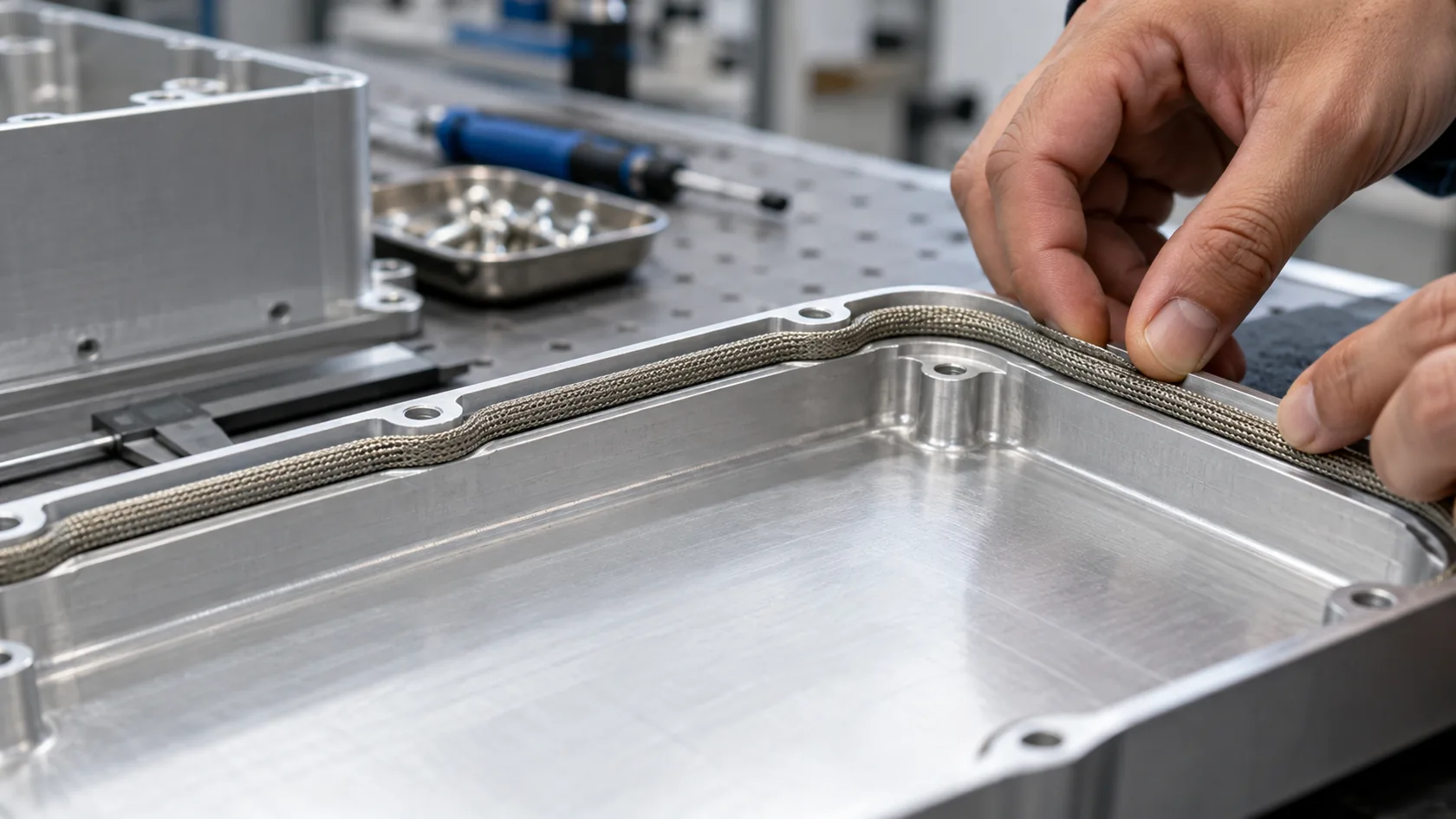
Conductive gaskets can connect a perimeter seam while also supporting an EMC-oriented closure strategy. They are different from ordinary environmental gaskets: material conductivity, compression range, surface contact, galvanic compatibility, closure spacing, and environmental sealing all need review. A soft conductive gasket cannot compensate for a warped lid or widely spaced fasteners.
NIST notes that shielding performance depends on construction details including joints, seams, apertures, and geometry—not merely the base metal (NIST Technical Note 1099). The practical implication is that a conductive gasket belongs in a complete seam design, with a representative test plan, rather than as a late material callout.
I keep conductive and weather-sealing decisions together. A seam can be dry yet electrically poor, or conductive in a fresh sample yet lose environmental performance if compression and drainage were never considered.
Spring Fingers, Clips, and Sliding Contacts
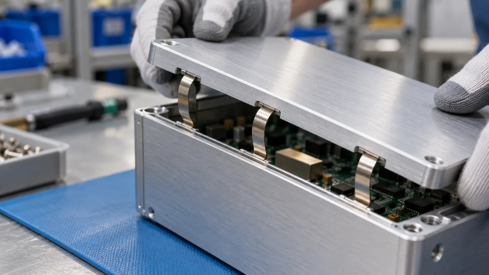
Spring fingers and clips suit removable covers, sliding parts, and locations where repeated contact is expected. They can provide many distributed contact points without a bulky braid, but they need stable placement, suitable counterface finish, clearance from pinching, and a retention method that survives assembly and service.
They are especially sensitive to mechanical reality. A finger that is flattened by an over-tight cover, smeared with paint, or placed beside an irregular cut edge may look present during inspection but provide unreliable contact in use. Keep their engagement path and mating surface clear on the drawing.
For high-use covers, I prefer a spring-contact approach only after checking how the customer actually opens and closes the product. The service motion matters as much as the electrical sketch.
Coatings, Oxides, and Prepared Contact Lands
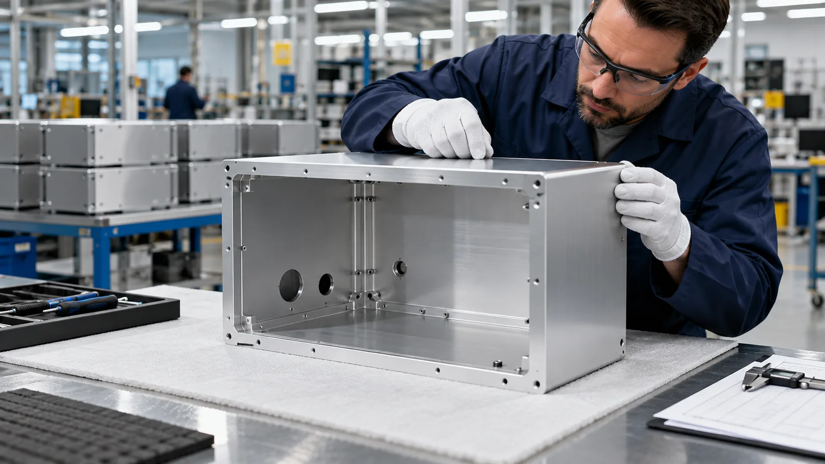
Aluminum’s natural oxide layer and many cosmetic or corrosion-protection finishes can change a joint’s electrical behavior. The correct response is not to treat finish as the enemy. It is to define the interface: mask a local land, use an approved treatment, specify an appropriate plating stack, or provide a separate controlled bonding feature.
A drawing should show where treatment is excluded or controlled, how the area is protected after assembly, and what substitutions require approval. These details need to be reviewed with corrosion exposure, dissimilar-metal contact, sealing, and future servicing—not just at the coating supplier.
The factory lesson is simple: a vague note such as “remove paint for grounding” creates random rework. A dimensioned contact region and an assembly photo standard give everyone the same target.
Cable Shields, Connector Shells, and Entry Interfaces
Cable entry often breaks an otherwise thoughtful enclosure strategy. A shielded connector shell, gland, bulkhead, or conductive conduit interface may need a defined bond to the enclosure, but the correct arrangement depends on the finished apparatus, cables, frequencies, installation, and applicable requirements. It should not be inferred from the enclosure wall material alone.
Keep this interface separate from a general protective-earth terminal in the drawing review. A cable shield termination can have different geometric and EMC needs than a low-frequency safety connection. If insulation or isolation is intentional, document it rather than allowing a hardware change to create an accidental path.
When quotes arrive, I look for a specific entry-interface detail rather than a promise that the case is “EMC ready.” That phrase is too broad to verify.
Corrosion and Service Decide Whether the Bond Lasts

Freshly assembled metal contact tells only part of the story. Humidity, salt, chemicals, thermal cycling, fretting, vibration, and repeated access can change a connection long before the enclosure looks obviously damaged. The risk increases where aluminum, copper, steel, plating, and retained moisture meet.
Review the whole stack: enclosure alloy, fastener and strap materials, coatings, gasket drainage, edge protection, cleaning exposure, and service interval. Any corrosion test or continuity limit should be tied to the product’s stated environment and governing requirement, not borrowed as a generic marketing number.
I have more confidence in a modest bond designed for accessible inspection and durable materials than a clever hidden contact with no plan for moisture, wear, or replacement hardware.
Put Bonding Details Into the Drawing and Control Plan

The fabricator needs a controlled requirement, not an implied one. A good package identifies the bonding function, endpoints, approved parts, finish/contact treatment, assembly sequence, and verification evidence. The responsible electrical designer owns the required performance; the enclosure team converts it into repeatable manufacture.
| Control item | What it prevents |
|---|---|
| Identified bond endpoints and method | Missed lids, panels, or cable interfaces |
| Hardware and finish stack-up | Unreviewed substitutions and insulated joints |
| Assembly photo or work instruction | Operator-to-operator variation |
| First-article and production check | Passing a neat prototype but drifting in volume |
| Defined change-control owner | A mechanical cost change breaking an electrical feature |
I would rather see a short, precise bonding table on a drawing than a general instruction buried in an email. It makes quoting fairer, first-article review faster, and later changes much safer.
Conclusion

Aluminum enclosure bonding is not one component choice. Screws can work well at controlled rigid joints. Straps make removable parts explicit. Conductive gaskets and spring contacts address particular seam and service conditions. Every method still depends on contact treatment, mechanical loading, corrosion exposure, assembly control, and the actual electrical purpose.
After years of reviewing custom enclosure details, my practical rule is to design the bond where it will be made, not where it is merely convenient to draw. Send us the enclosure layout, removable-part plan, intended environment, cable entries, and the qualified bonding requirement. We can help review the contact lands, hardware, finishes, and assembly controls before production turns an assumption into a costly change.