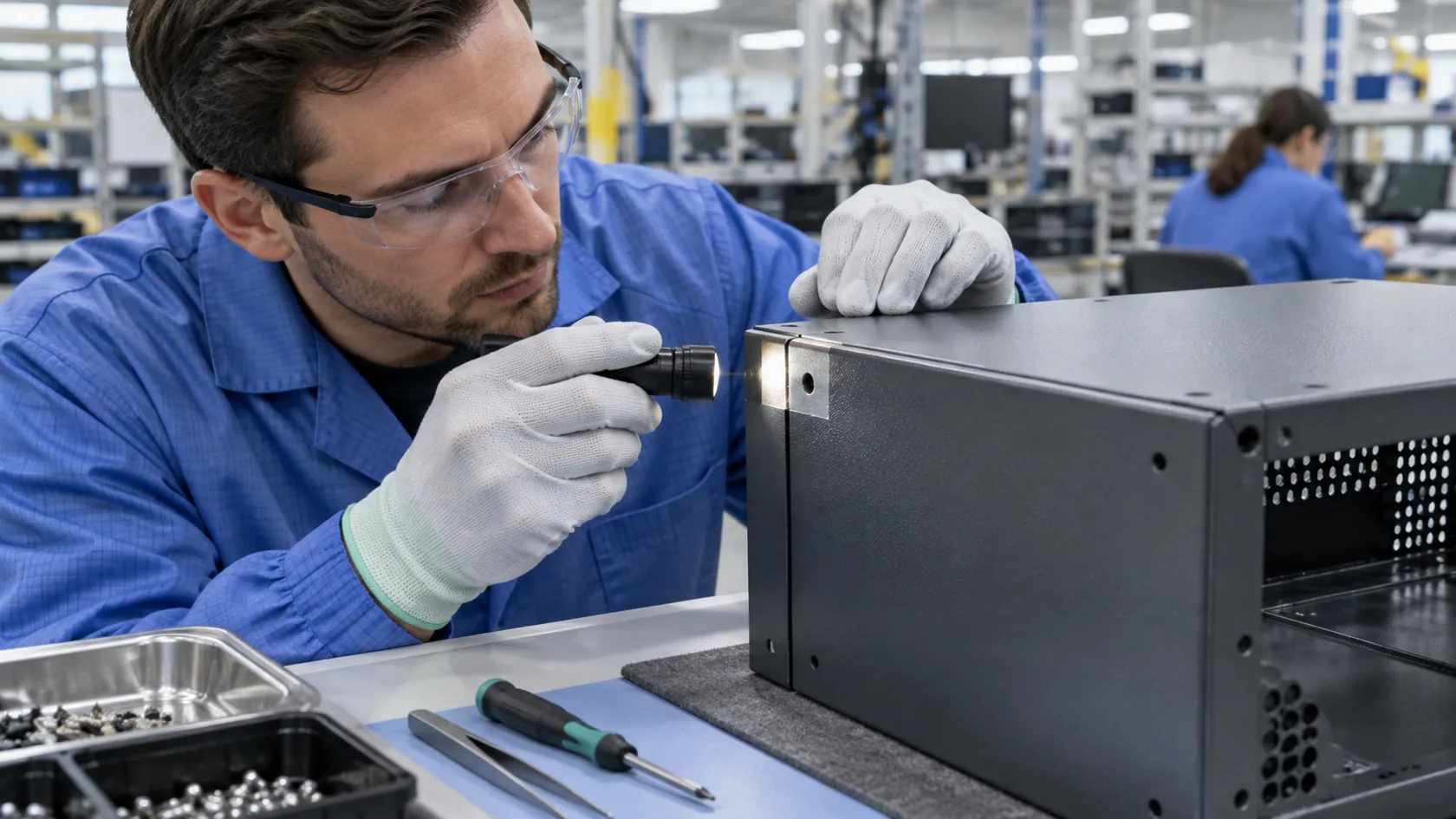
Skip to content
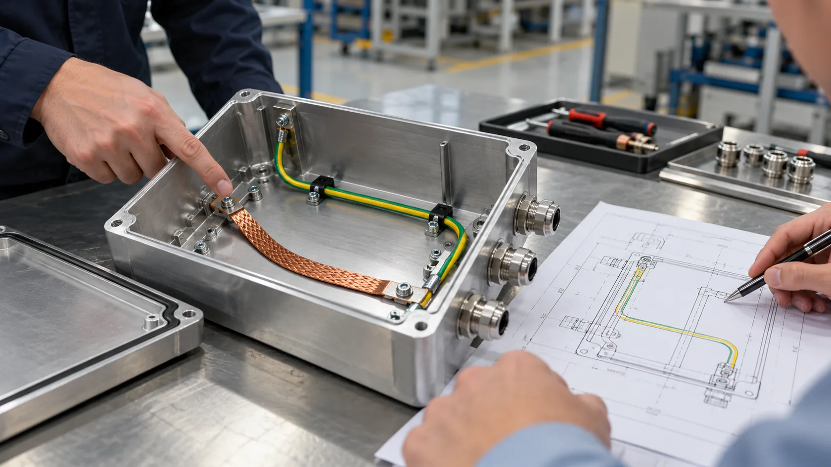
An enclosure drawing can show a green-yellow conductor, a ground symbol, and a metal lid, then still leave a critical question unanswered: what exactly is meant to be grounded, and what parts must be bonded together? That ambiguity usually surfaces when the coating is already approved or when a first article arrives with a removable cover that is mechanically secure but electrically isolated.
For a custom enclosure, grounding and bonding are related but not interchangeable. Grounding establishes a deliberate reference or fault-current path for the system. Bonding joins conductive parts so they remain at a controlled electrical relationship. The exact implementation must follow the product, installation rules, applicable standard, and qualified electrical design—not a generic factory habit.
In my experience, treating the two words as one requirement is how a small missing contact land becomes a late redesign. The practical starting point is to separate the jobs each connection must do.
The Short Difference: Where the Connection Goes
Grounding connects a circuit or equipment to earth, or to a conductor serving as that reference, for a defined electrical purpose. OSHA describes grounding as intentionally creating a low-resistance path to earth, and distinguishes system grounding from equipment grounding in its electrical-safety guidance.
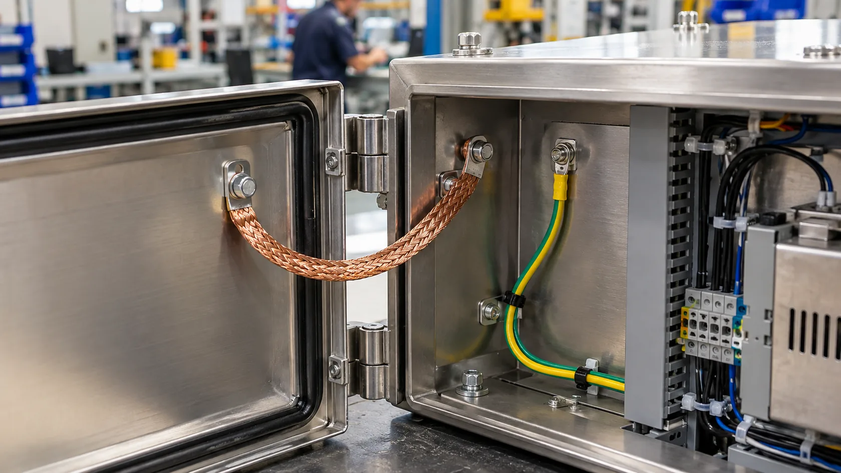
Bonding connects conductive objects to one another. In an enclosure, that can mean bonding a door, removable lid, panel, conduit, cable-shield interface, or internal mounting plate to the main chassis so unexpected voltage differences are reduced and continuity is maintained where the design needs it.
| Question | Grounding | Bonding |
|---|---|---|
| Main purpose | Establish a defined reference or protective fault path | Keep conductive parts at a controlled electrical relationship |
| Typical enclosure connection | Protective-earth terminal or equipment grounding conductor | Lid strap, bonding jumper, conductive joint, or dedicated hardware |
| Common mistake | Assuming any metal contact reaches the intended protective path | Assuming a tight painted joint is electrically continuous |
I tell buyers to put both nouns on the drawing rather than use a single note saying “ground enclosure.” That gives the electrical designer and fabricator a much clearer handoff for the next review.
Protective Earth Is a Designed Path, Not a Decorative Terminal
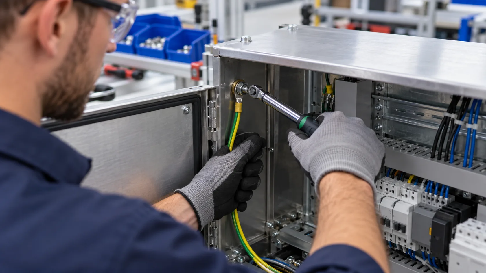
For mains-powered equipment, an exposed conductive enclosure may need an equipment-grounding or protective-earth connection that works with the complete electrical protection scheme. The relevant path, conductor sizing, termination, fault-current capacity, and installation rules are matters for the responsible electrical designer and the applicable code or standard.
The enclosure manufacturer can make that requirement easier or harder to achieve. A dedicated stud or terminal needs enough space for the specified lug and tool access. Its base material, plating, hardware stack-up, locking method, finish exclusion, and marking must all agree with the approved design. A stud placed behind a PCB, under a cosmetic cover, or on an unprepared coated surface invites assembly variation.
OSHA notes that an equipment-grounding path must be permanent and continuous, and that bonding conductors used for electrical continuity must safely carry imposed fault current where applicable. That is a useful safety principle, not a shortcut for selecting a design without qualified review.
On real projects, I look at the installation sequence as carefully as the terminal itself. A good connection on a CAD view is not enough if the assembler cannot consistently make it during production.
Bonding Keeps Separate Metal Parts From Becoming Separate Electrical Parts
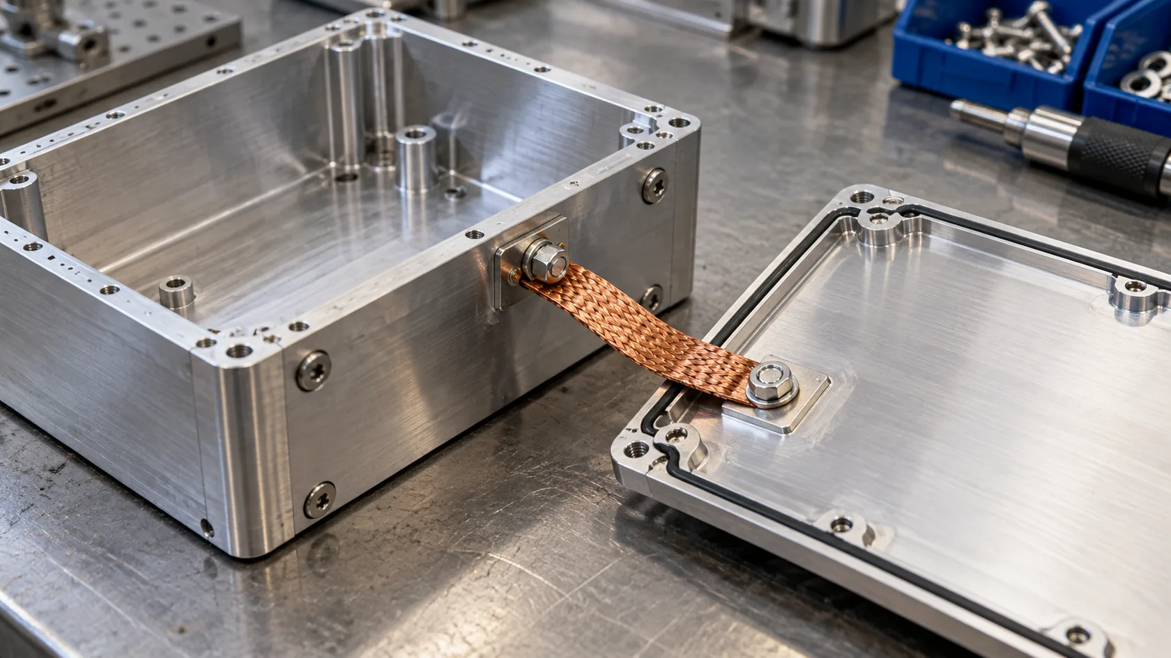
A cabinet body, removable cover, door, and mounting plate may all be metal, yet they may not be reliably bonded after paint, anodizing, oxide growth, loose fasteners, or repeated service. Mechanical closure only proves that the parts stay together. It does not automatically prove a low-impedance electrical connection for the required purpose.
Common bonding locations
- Removable lids and service doors
- Hinged panels with painted hinge interfaces
- Separate sheet-metal panels and internal mounting plates
- Cable shields or conductive connector shells at the enclosure boundary
- Conduit or cable-entry hardware when the system design requires continuity
A bonding strap, conductive gasket, spring finger, serrated hardware, masked land, or direct metal-to-metal interface may each be appropriate under different conditions. The choice depends on current, frequency, corrosion exposure, opening cycles, allowable contact resistance or impedance, and how the product is tested.
I pay extra attention to covers that will be opened for service. The lightest, cheapest strap is not automatically the right answer if bending, paint wear, or a poor fastening sequence makes the contact unreliable over the product’s life.
Coatings and Oxides Change the Electrical Interface
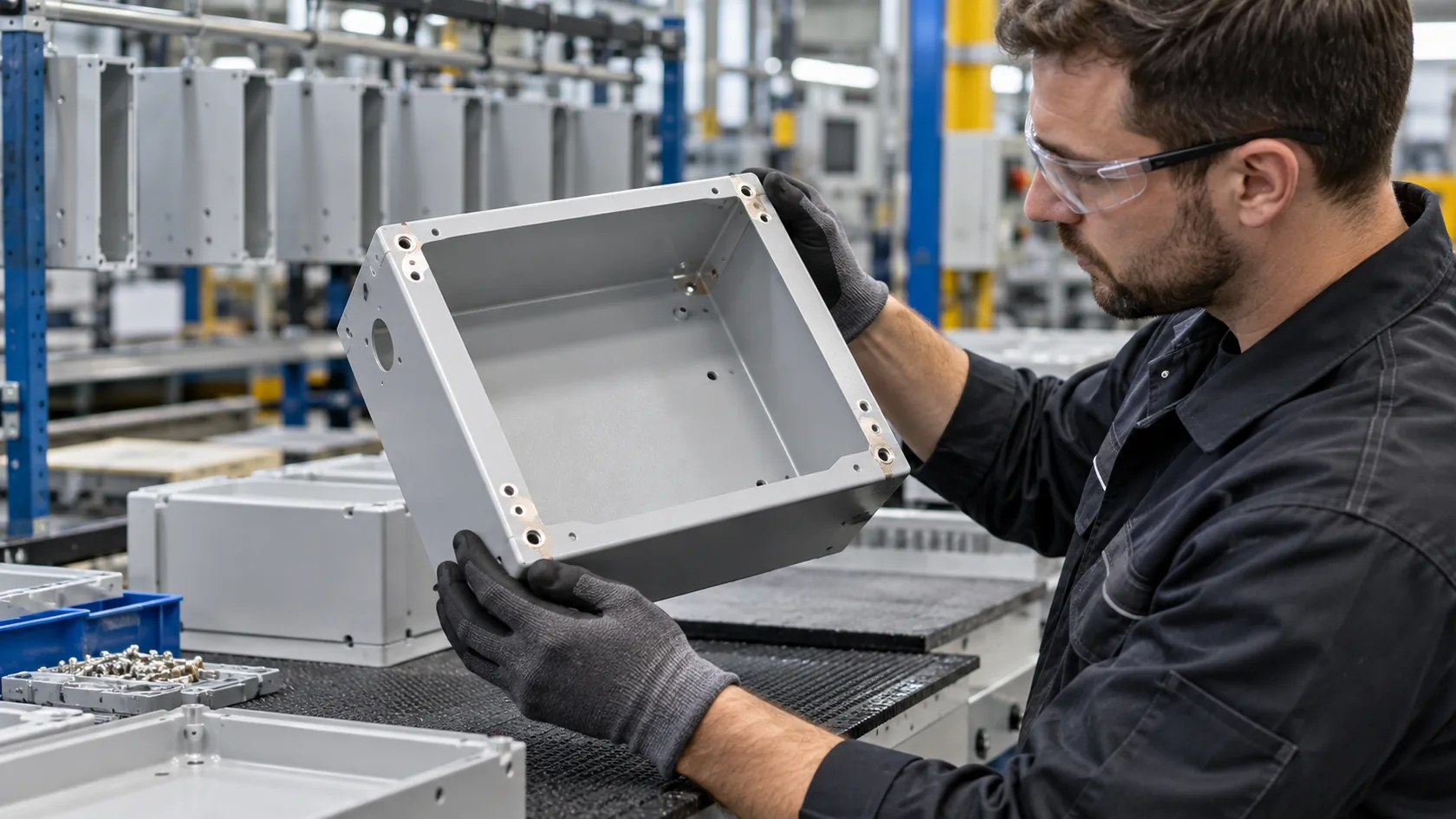
Powder coating, paint, anodizing, chemical conversion coatings, and plating solve different corrosion, appearance, and process problems. They can also change the electrical behavior of an interface. A finish that is excellent on the outside of a cabinet may be unsuitable on a connection that needs deliberate electrical continuity.
The answer is not to leave all metal bare. It is to show the intended contact regions in the drawing and finishing instructions. For example, the design may define a masked land under a bonding lug, an approved conductive treatment at an interface, or hardware that penetrates a coating in a controlled way. Any finish exclusion needs corrosion and service consideration as well.
The OSHA guidance on protective grounding and bonding highlights the importance of an equipotential zone; in enclosure work, the practical lesson is to control the interfaces rather than assume a painted metal assembly is continuous.
From the factory side, I prefer one clear finish map over verbal instructions passed between fabrication, coating, and assembly. That small document prevents a surprising number of rework discussions.
Corrosion Protection Cannot Be an Afterthought at a Bonding Point
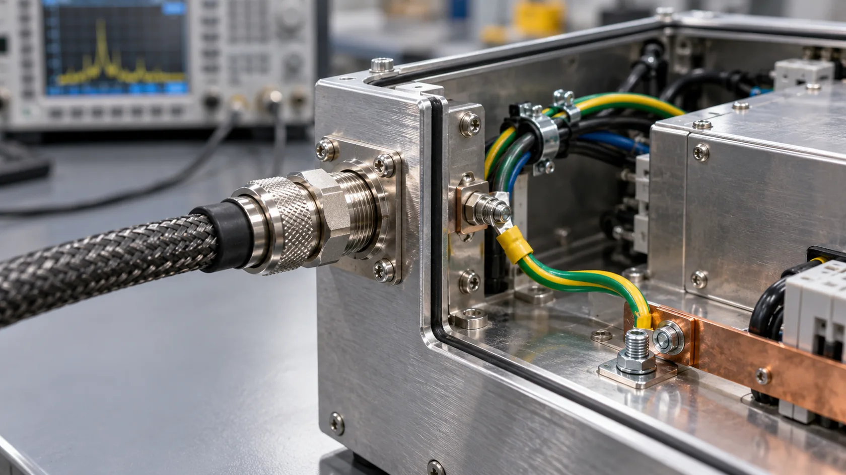
Bare contact at the day of assembly is not the same as durable bonding after humidity, salt, cleaning chemicals, vibration, or thermal cycling. Dissimilar metals can add galvanic-corrosion risk, while a loose strap or contaminated land can change contact quality long before a visual inspection shows an obvious problem.
For outdoor, wash-down, marine-adjacent, or chemically exposed equipment, the electrical interface needs to be reviewed together with the material stack: enclosure alloy or steel, hardware, strap material, plating, seal, drainage path, coating edge protection, and maintenance access. The required validation method must match the product environment; a generic salt-spray number alone does not define a reliable assembly.
I have seen teams protect every visible surface, then leave the one critical bonding interface without a service plan. It is better to agree on approved hardware and inspection points while the first article is still easy to change.
Grounding, Bonding, and EMC Are Connected but Not the Same Claim

Bonding can be important for shielding effectiveness and cable-interface behavior, especially at seams, apertures, and connector shells. But a bonding strap does not turn an enclosure into proof of electromagnetic compatibility, and a protective-earth terminal is not a complete EMI-control strategy.
EMC performance depends on the whole apparatus: circuit layout, cable shielding and termination, connector design, seam geometry, apertures, coatings, operating modes, installation, and the relevant test configuration. The European Commission’s EMC Directive overview likewise treats EMC as a requirement for equipment in its electromagnetic environment, not as a property claimed from one enclosure feature.
For high-frequency behavior, geometry and interface impedance can matter more than a DC continuity reading alone. For protective safety grounding, the applicable fault path and protective-device operation matter. These are different engineering questions that may share hardware but cannot be merged blindly.
When a buyer asks us for an “EMC-grounded box,” I ask for the product test plan, cable interfaces, opening layout, and intended earth arrangement before promising a fabrication detail. That keeps the enclosure scope honest.
Turn Requirements Into Drawing Notes and Assembly Controls
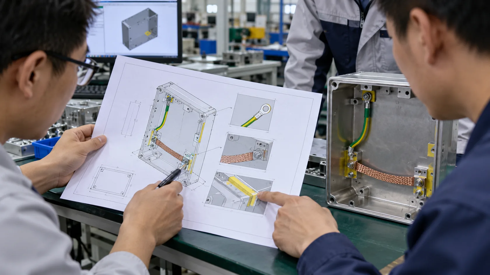
The most useful enclosure package identifies function, location, and verification method instead of relying on a vague ground symbol. The electrical designer should own the requirement; the fabricator should turn it into controlled geometry, finishes, parts, and assembly work.
| Drawing or work-instruction item | Why it matters |
|---|---|
| Protective-earth terminal location and hardware stack | Defines the intended equipment-grounding connection |
| Bonding jumper part and endpoints | Prevents an improvised strap or missed removable part |
| Finish masks or conductive-treatment areas | Makes required contact repeatable through coating |
| Fastener type, torque, and approved substitutions | Protects the assembled interface from uncontrolled changes |
| Inspection method and acceptance criteria | Gives quality control a practical, agreed check |
NASA’s grounding handbook is written for uncrewed spacecraft, so it is not a design code for ordinary industrial enclosures. Still, its separation of system grounding architecture from bonding guidance is a useful reminder that these topics have distinct design roles; its document directs bonding readers to a separate standard. See NASA-HDBK-4001A.
I would rather receive a drawing with three well-defined connection notes than a more polished model with the electrical intent left to interpretation. It gives purchasing a fairer basis for comparing quotes too.
Verify the Production Assembly, Not Just the Prototype Idea
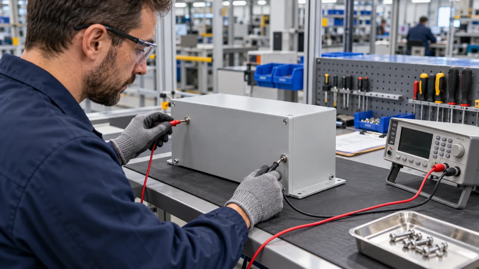
A prototype can show that a strap fits and a terminal is accessible. Production brings the variables: coating thickness, supplier substitutions, hardware batches, operator sequence, torque tools, packaging damage, and repeated opening. The verification plan should be proportional to the requirement and run by people qualified for the applicable safety and product standards.
Useful production evidence may include material and finish records, photos of masked lands before assembly, approved hardware identification, dimensional checks at critical interfaces, and documented continuity or other specified electrical tests. The test method and acceptance limits must come from the responsible design and compliance team. A factory should not invent a pass value just because it owns a meter.
For protective grounding, remember that a low reading at a convenient point does not by itself prove the installed product meets every relevant safety requirement. For EMC, a continuity check also cannot replace representative system testing.
My rule is simple: test the feature in the condition the customer will ship and service, not only in the neatest sample condition. That produces evidence buyers can actually use.
Questions to Settle Before You Release an Enclosure
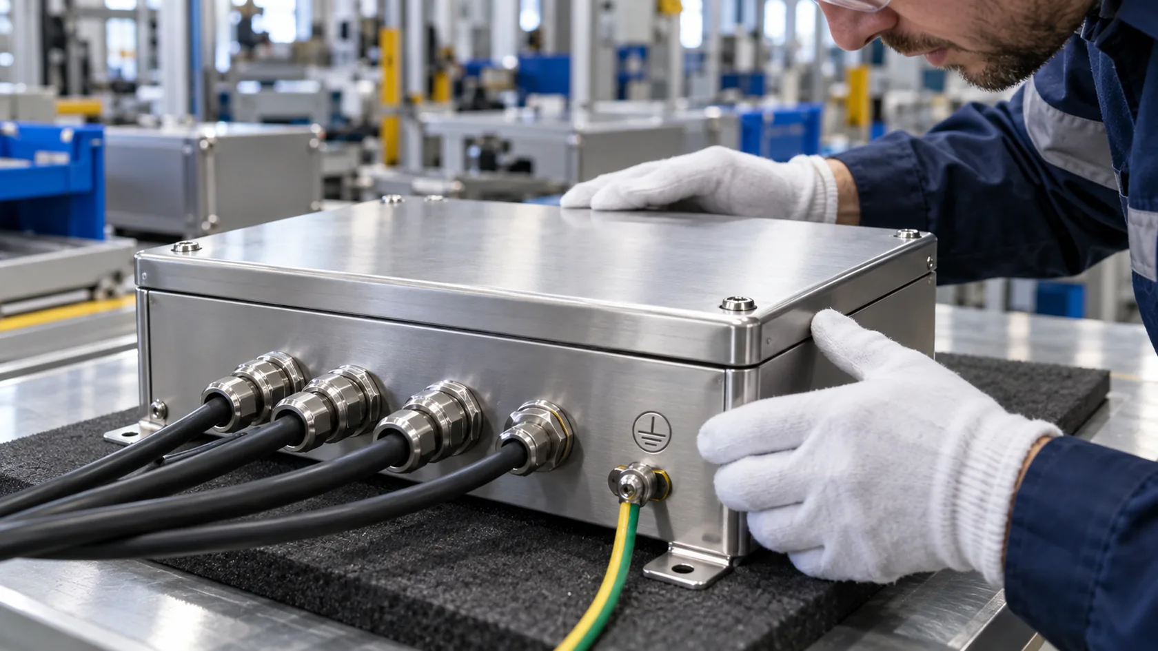
Before the tooling release or first production order, the buyer, electrical designer, and enclosure supplier should be able to answer these questions:
- Which connection is protective earth or equipment grounding, and which standard or installation rule governs it?
- Which removable or separate conductive parts require bonding, and for what electrical function?
- Where must coating be masked, removed, or replaced with an approved treatment?
- Which hardware, strap, cable interface, and assembly sequence are controlled?
- What verification is required on the first article and on production assemblies?
- Who owns the system-level safety and EMC validation for the finished equipment?
The OSHA definition of an equipment grounding conductor is a useful reference for why an enclosure connection needs a real path back to the appropriate source arrangement, rather than an isolated metal feature.
I find that six direct questions expose most uncertainty before it becomes a tooling change. They also let a supplier flag manufacturability risks early, when the drawing can still absorb a sensible adjustment.
Conclusion
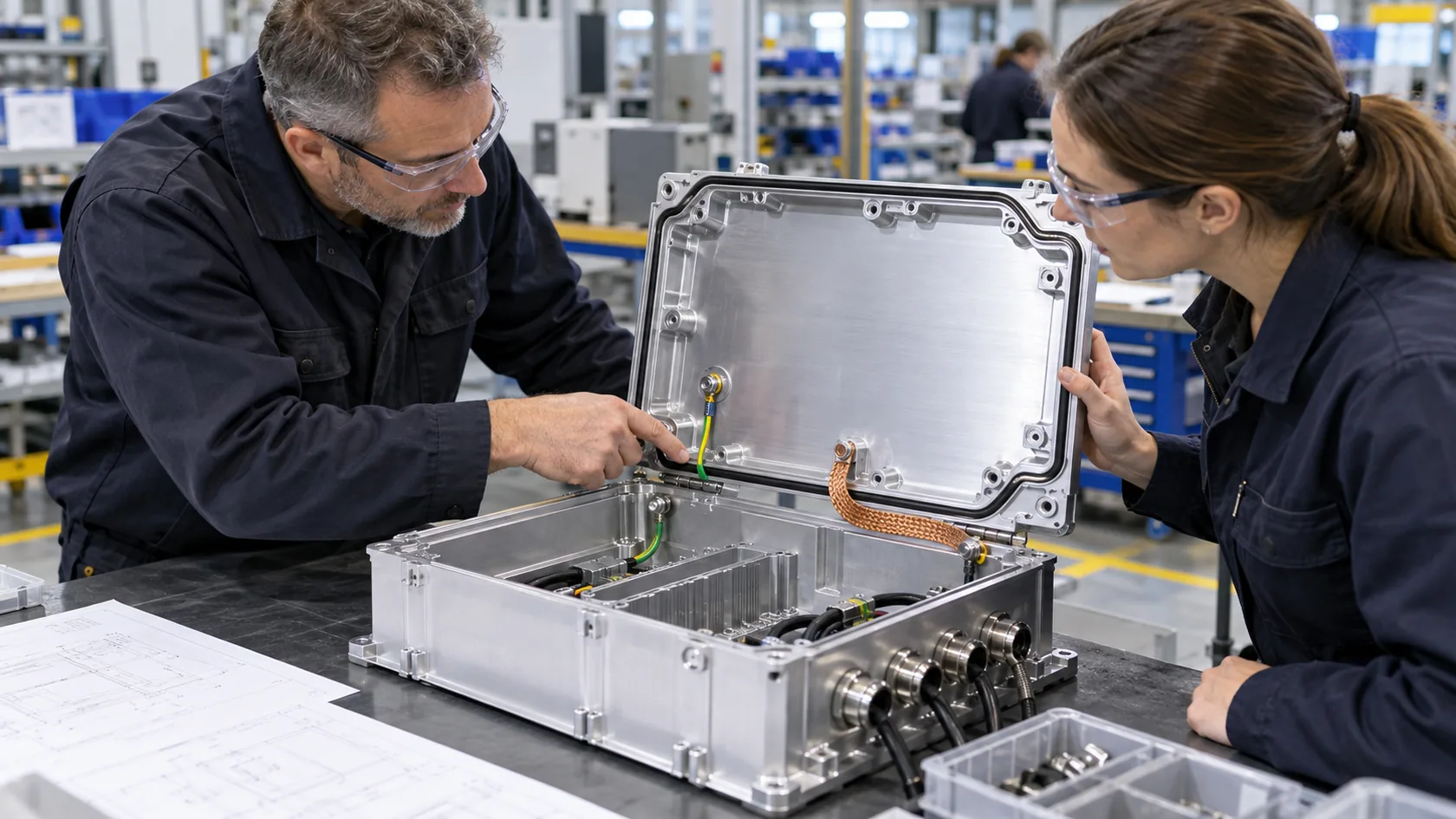
Grounding and bonding work together, but they do different jobs in enclosure design. Grounding concerns the intended reference or protective path. Bonding concerns controlled continuity between conductive parts. A terminal, lid, coating, fastener, cable entry, and test record each matter only when they support the defined electrical function.
After years of quoting and building custom enclosures, I have learned that these details are easiest to get right when the electrical intent is visible before fabrication begins. Send the enclosure drawing, power and cable-entry plan, target environment, and any required test basis. We can then review the earth terminal, removable parts, finish interfaces, and production checks before a first article locks in the wrong assumption.