Skip to content
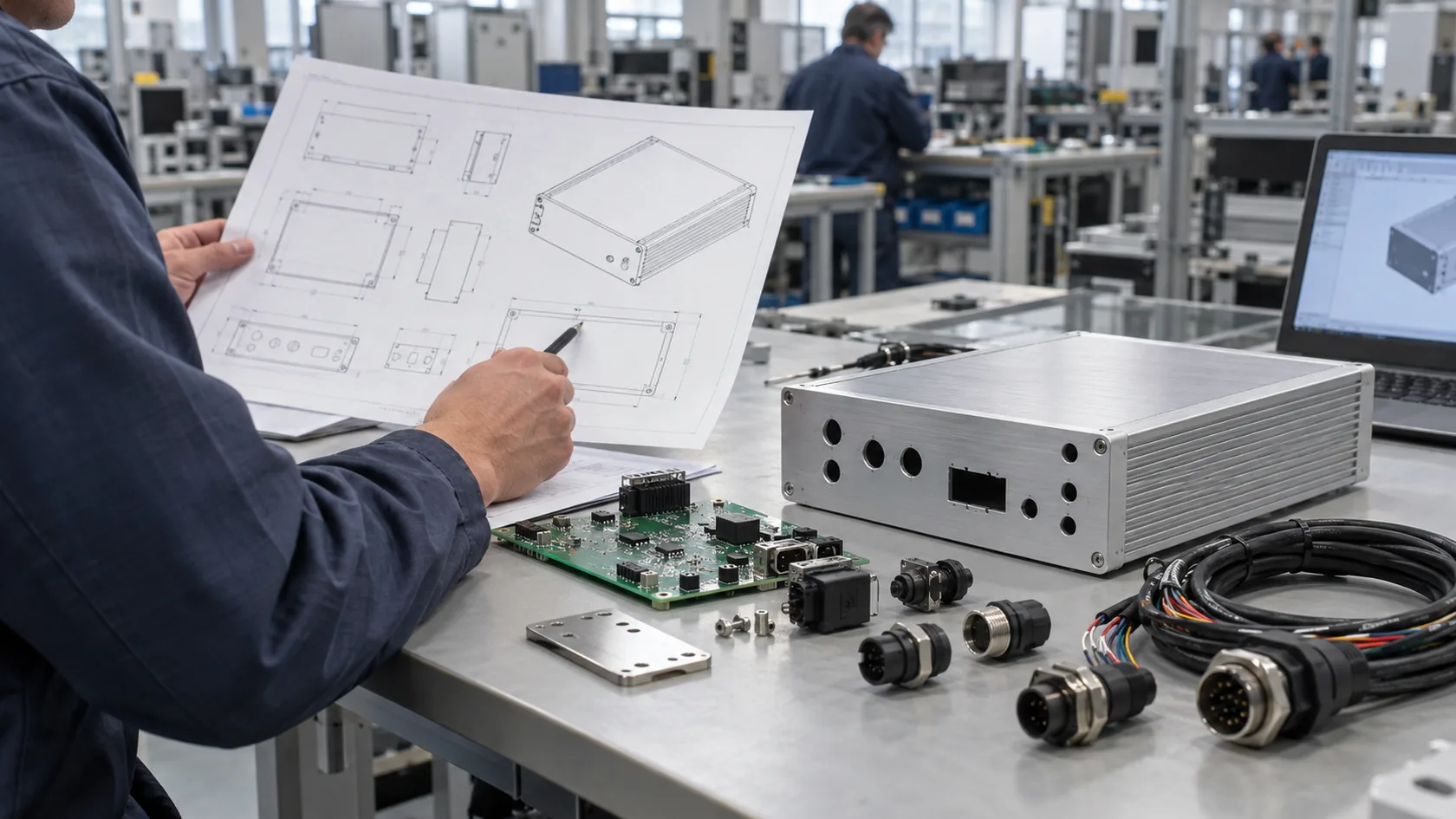
The outside dimensions are usually the first numbers a buyer sends me: 160 × 120 × 75 mm, for example. They matter, but they are only the envelope. A box can be large enough for a PCB on screen and still become difficult to machine, hard to assemble, too warm in service, or unexpectedly expensive when production starts.
That happens because an enclosure is not an empty volume. It is a manufactured interface between the electronics, connectors, mounting method, environment, finish, tools, and people who will assemble and service it. When size is the only selection rule, those interfaces are often discovered after the drawing has already become a quotation—or worse, after the first batch.
In my experience, the most useful early question is not “Which standard size fits?” It is “What must fit, align, seal, dissipate, and be made repeatedly?” This article explains the manufacturing problems that size-only selection tends to hide, and the details I would settle before cutting material.
The External Envelope Does Not Define the Usable Interior
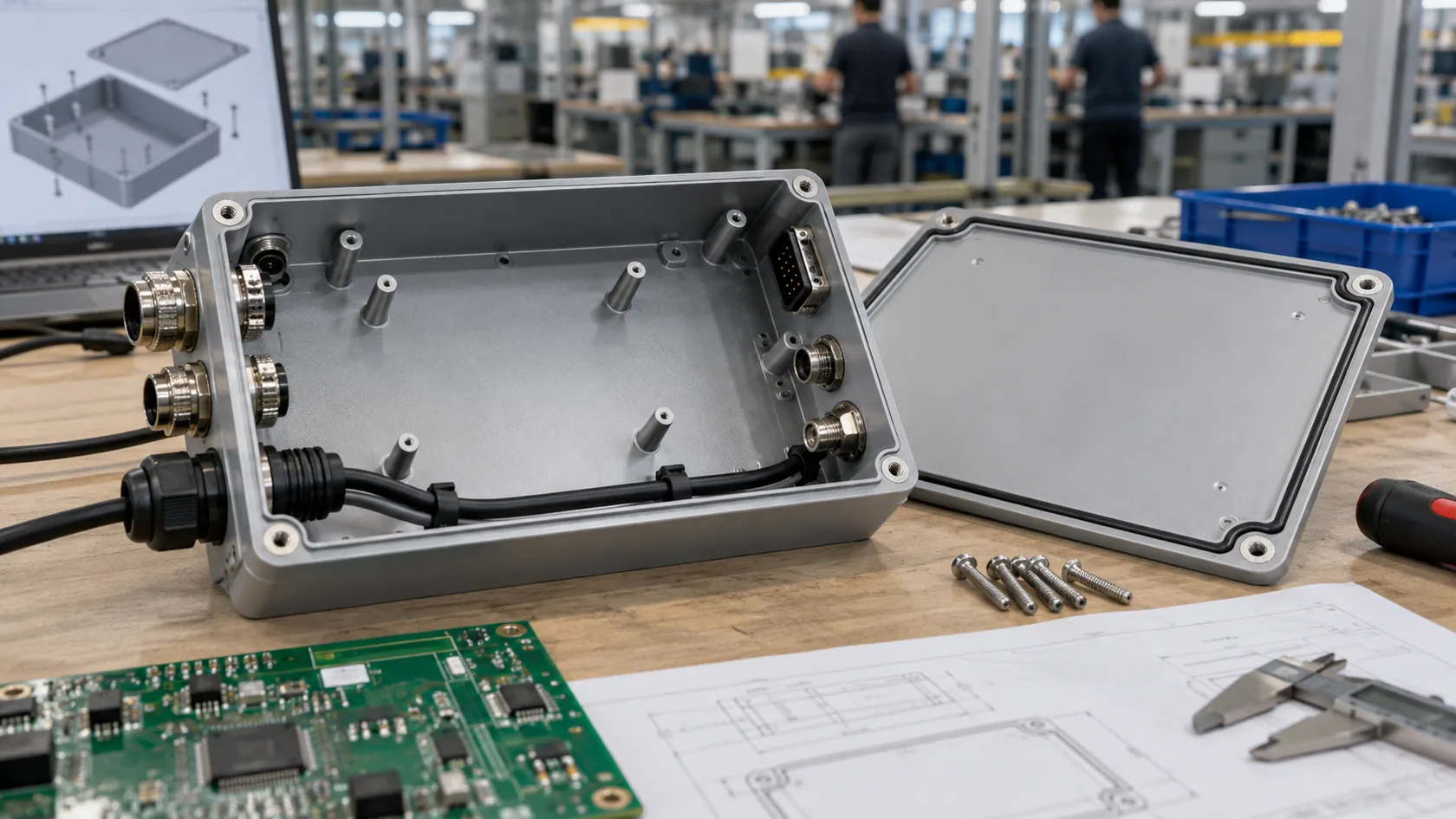
A catalog dimension normally describes the outside of the enclosure. The usable cavity is smaller after wall thickness, cover overlap, internal ribs, screw bosses, gasket channels, mounting flanges, and clearance for assembly are considered. A board that fits in a CAD bounding box may collide with a lid screw or leave no route for a connector harness.
Build an interface map before choosing the housing
Start with the actual objects that need space, not only their nominal length and width:
| Interface | Question to settle | Common size-only surprise |
|---|---|---|
| PCB | Datums, edge clearance, mounting-hole positions | Standoffs do not align with the production board |
| Connectors | Mating plug envelope and cable bend radius | A connector fits the cutout but the plug cannot be inserted |
| Fasteners | Driver access and thread engagement | A corner screw is blocked after the lid is installed |
| Lid and gasket | Overlap, compression path, service access | The sealing joint consumes the assumed free space |
| Mounting | Brackets, rails, wall clearance | The installed unit is wider or deeper than the enclosure drawing |
I prefer to see the real mating connectors, cable diameters, and a dimensioned PCB file at this stage. A few millimeters reserved around an interface often prevent a whole new panel later. Once the internal geometry is visible, the next decision is whether the selected process can make it economically.
Size Suggests a Process, But Does Not Select One
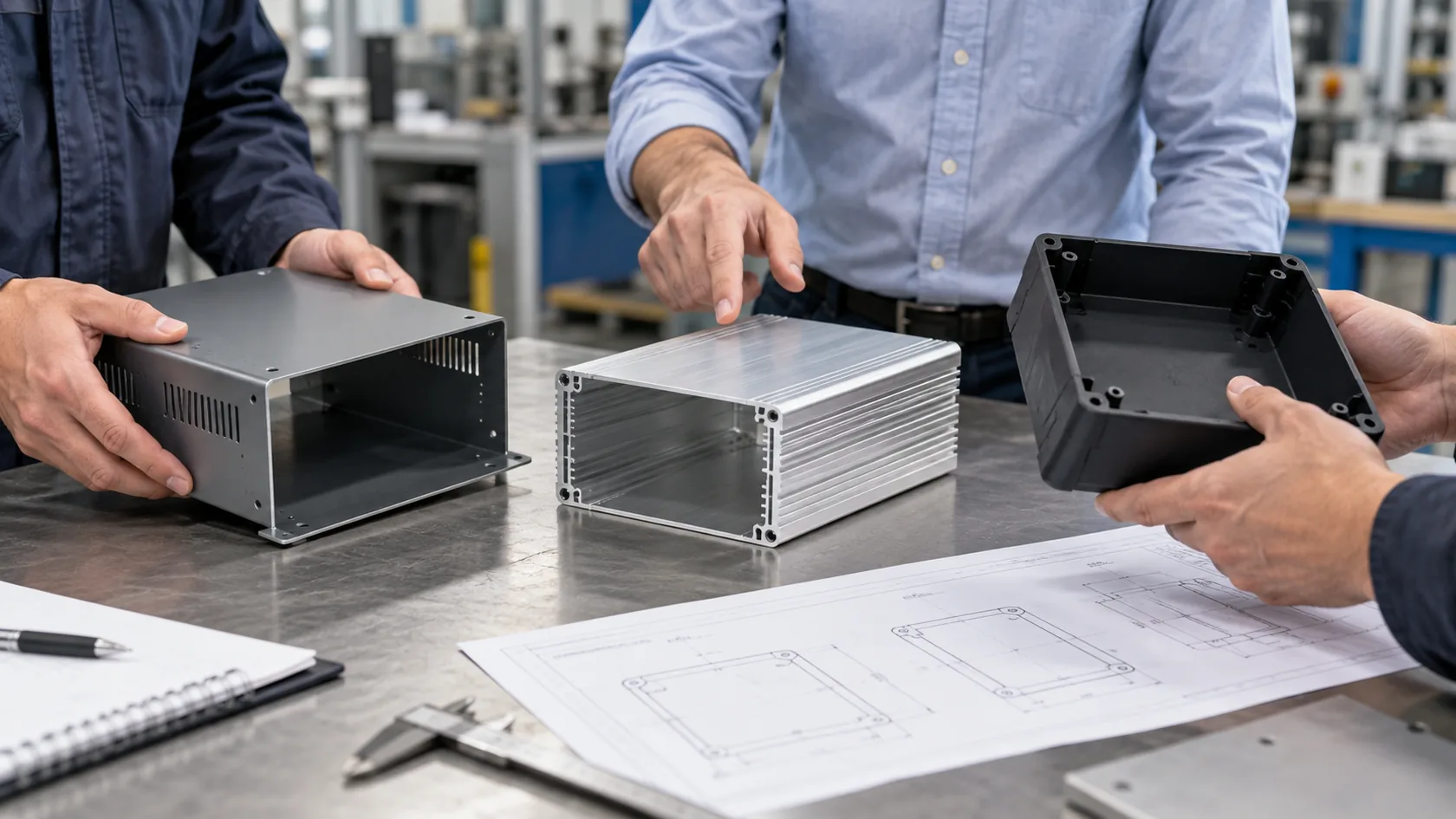
The same outer size can be produced as bent sheet metal, an extruded aluminum body with machined end plates, a CNC-machined enclosure, a die casting, or an injection-molded plastic housing. Each route has different rules for corners, wall sections, cutouts, tooling, draft, joining, and redesign.
Match the geometry and volume to the production route
For a small pilot run, CNC machining or sheet metal may absorb design changes more easily than dedicated tooling. At a stable, higher volume, molding or die casting can be appropriate, but only if the geometry is designed for the tool and the program can carry that investment. Protolabs’ overview of electronic-enclosure methods is a useful process comparison; it also notes that the enclosure can be an assembly rather than a single formed part.
For sheet metal, bends, bend relief, tool access, and the sequence from flat pattern to assembly matter. Its sheet-metal enclosure guidance makes the practical point that one bend can affect manufacturability elsewhere on the same part. For molded plastic, draft, wall consistency, ribs, gates, and ejection become part of the design, not factory details.
I would not choose injection molding solely because a small plastic box looks simple. A housing can be the right size yet require side actions, awkward parting lines, or changes that make a prototype route more sensible until the design is stable.
Wall Thickness and Corners Can Change the Part After It “Fits”
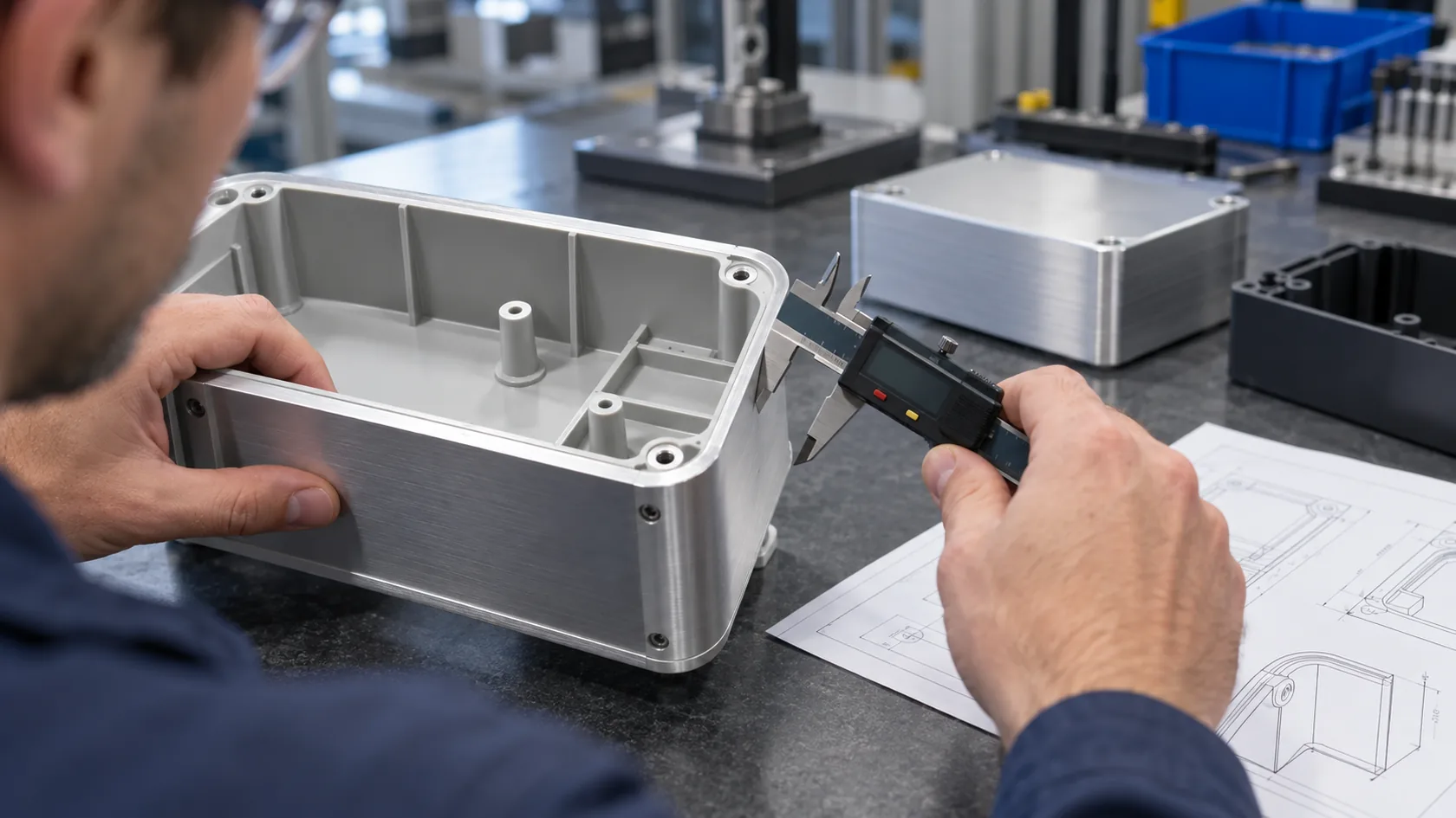
When a plastic enclosure is sized around the electronics without considering wall design, uneven cooling can create warp, sink marks, or dimensional movement. Thick corners and bosses are especially easy to create while trying to make room for screws or connectors. Autodesk’s manufacturability guidance explains why excessive variation in molded-part wall thickness can lead to longer cooling, deformation, filling problems, and surface defects.
Preserve function with ribs and sensible transitions
Uniform nominal walls are a starting principle, not a command to make every feature identical. A strong area may need a rib, a local boss, a fillet, or a gradual transition. The point is to create the function while giving the selected process a reasonable flow, cooling, or tool path. Sharp internal corners also affect tooling and stress concentration; in machined and cast work, radii must relate to the cutter or process capability.
For aluminum, a bigger enclosure can add rigidity, but it can also create longer spans that flex, more surface to finish, and a heavier part to handle. I look at how the lid, PCB, and mounting points support the structure before simply increasing the wall or the box. The material and finish then need to support the real environment rather than just the chosen dimensions.
The Environment Changes the Space You Need to Reserve
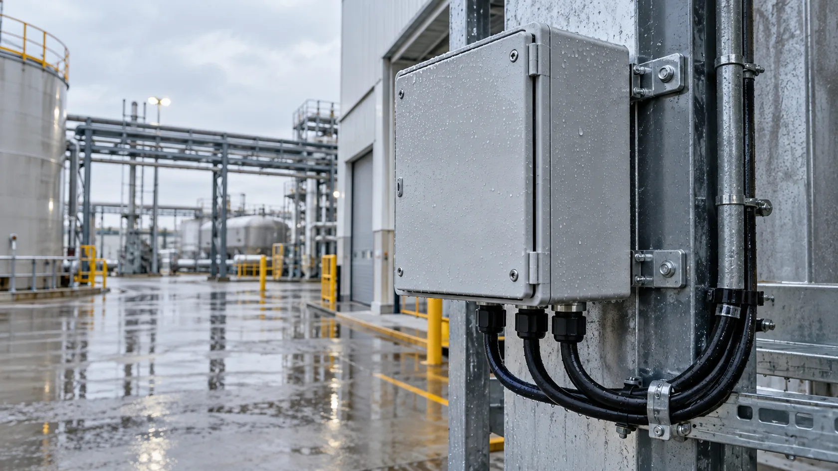
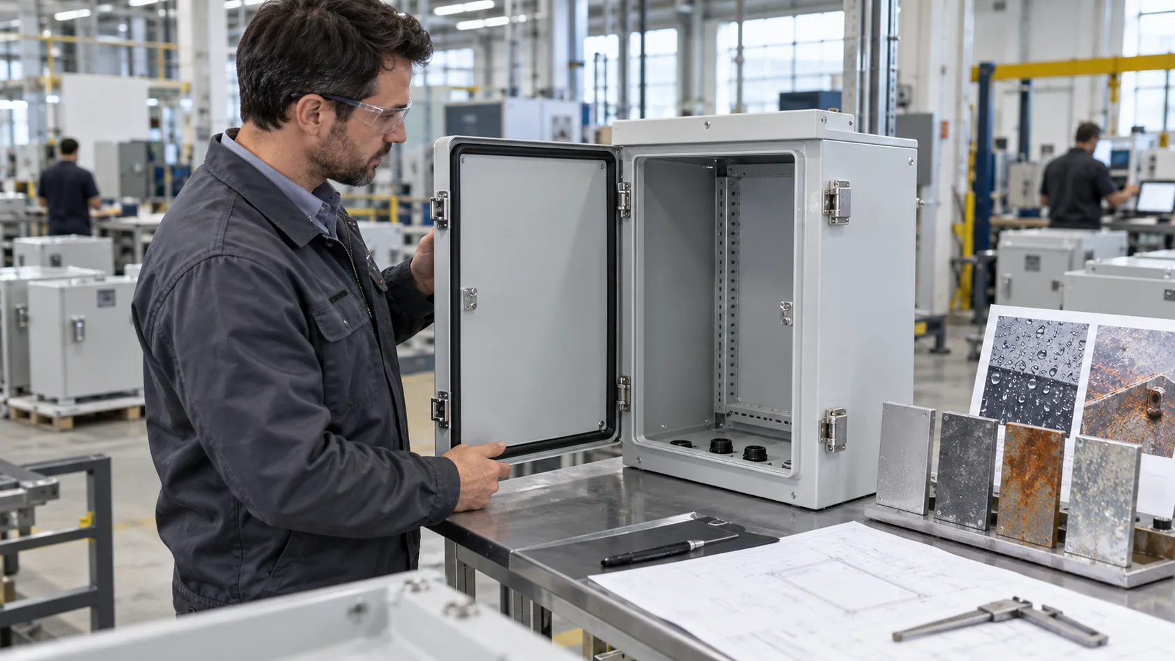
An indoor desktop device and an outdoor controller can share the same outside size but need very different enclosure details. Cooling paths, cable glands, drainage, corrosion protection, gasket geometry, access for maintenance, and mounting orientation all consume space and affect the manufacturing plan.
Treat ingress protection as an installed assembly
An IP rating is not a property of an empty shell. The cover joint, gasket compression, fasteners, cable entries, connectors, vents, mounting direction, and specified test arrangement determine the installed result. IEC describes IEC 60529 as the standard for IP Code classifications; the actual application still needs a configuration-specific review.
The usual size-only mistake is reserving room for a cable hole but not for the selected gland’s sealing range, locknut, torque access, bend radius, or mating connector. A deeper housing may improve cable routing but reduce available wall-mount clearance. A more sealed design may limit passive cooling and make condensation control more important. I ask buyers to choose the exposure and cable plan early, because changing a sealed panel after coating is rarely a small correction.
Tolerances and Datums Decide Whether Parts Assemble
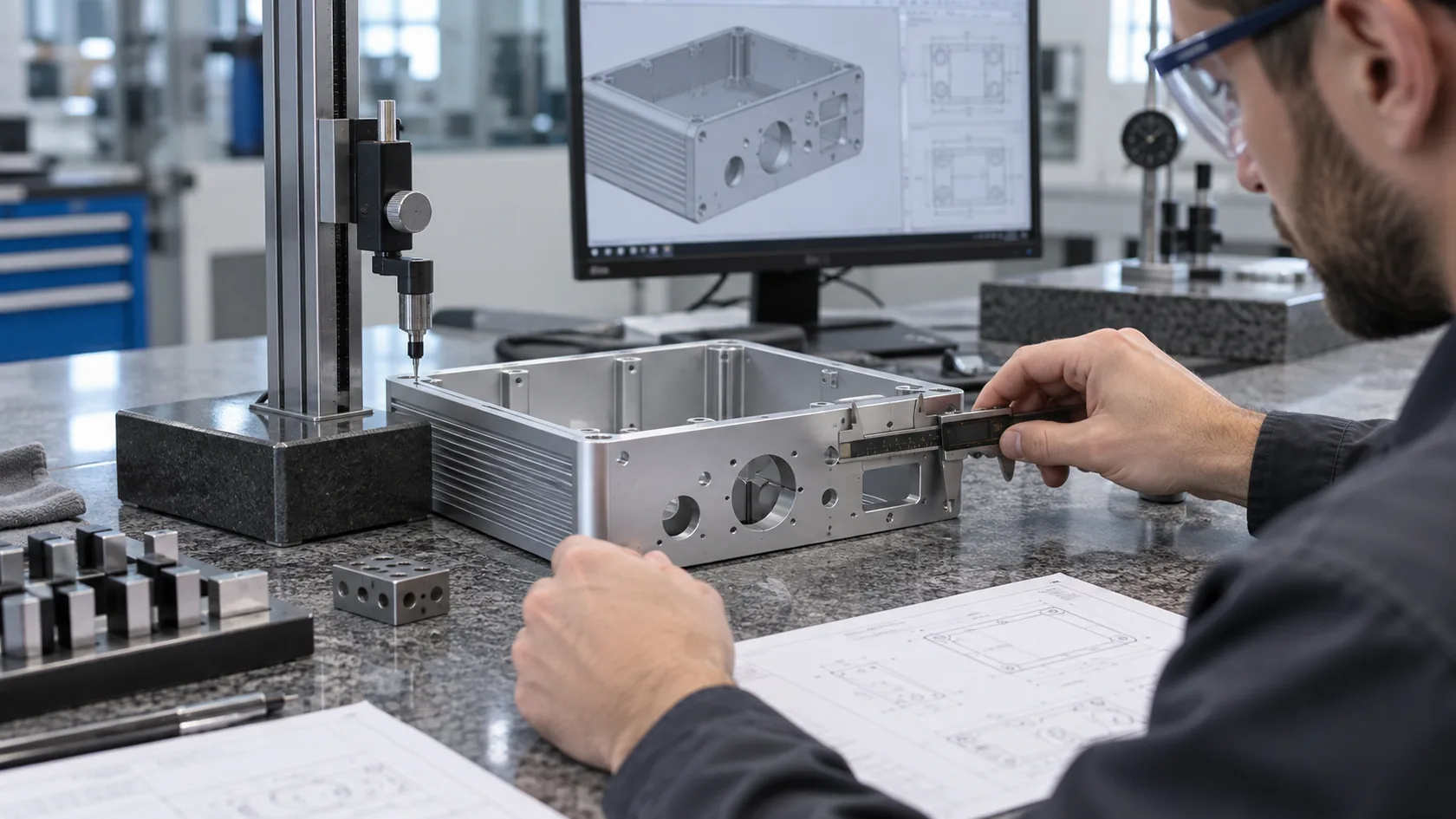
Nominal dimensions say where features are intended to be; tolerances define how much real parts may vary while still working. NIST notes that dimensions and tolerances are critical information for defining manufactured shape requirements, and geometric tolerancing communicates the allowed variation more completely than a list of box dimensions.
Control the relationships that affect function
Not every enclosure feature needs the same tolerance. Tightening every dimension raises cost and inspection effort without necessarily improving the product. Instead, establish functional datums and identify the relationships that truly matter: PCB mounting holes to connector cutouts, a lid to its gasket land, a rail clip to its mounting face, or an external opening to a mating plug.
| Feature relationship | Better drawing question | What goes wrong if omitted |
|---|---|---|
| PCB to front panel | Which board datum locates the connector cutout? | The connector is visibly off-center or will not mate |
| Lid to base | Which faces control the joint and screw pattern? | Uneven gap or unstable gasket compression |
| Bracket to housing | What surface establishes the mounting plane? | Rocking or misalignment in installation |
| Cutout to finish | Is final size specified before or after coating? | Coated parts bind with components that fit bare metal |
As Protolabs’ tolerance discussion points out, both insufficient and unnecessarily tight tolerances can cause trouble. My rule is simple: put precision where a part must locate, seal, mate, or look intentional; leave sensible process capability elsewhere.
Finishing and Assembly Need Their Own Allowance
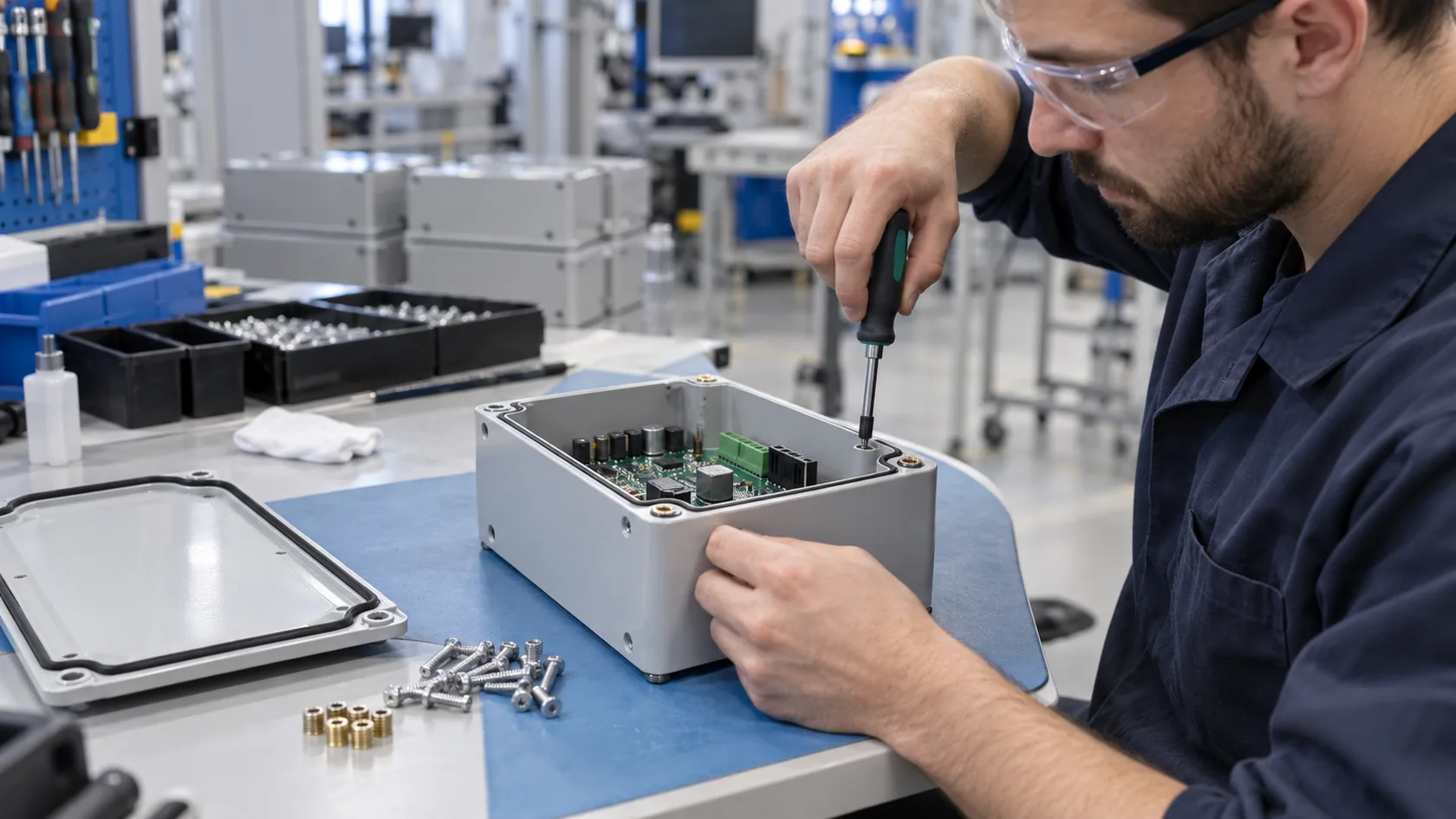
An enclosure can pass a bare-metal trial and then fail at assembly after powder coating, anodizing, printing, inserts, gaskets, or labels are added. These operations change surface condition, build sequence, handling requirements, and sometimes the fit of a functional interface.
Review the finished, assembled state
Before releasing a production drawing, confirm which dimensions apply before finish and which apply after finish. Check masking requirements for electrical bonding, contact surfaces, threads, and tight fits. Plan when threaded inserts are installed, how logos are aligned, and whether the operator can reach every screw after internal components are fitted.
I have seen a perfectly reasonable panel cutout become troublesome because the final connector flange and coating stack were never reviewed together. The solution was not “make the box larger”; it was to define the finished interface and the assembly order. This is also where a sample earns its value.
A DFM Review Turns a Size Choice Into a Buildable Design
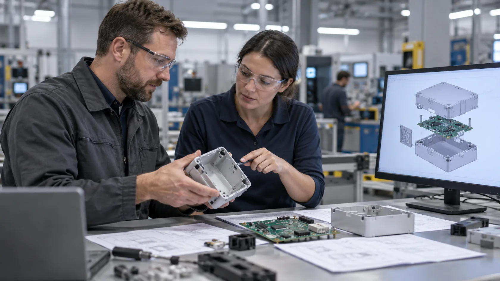
The practical cure for size-only selection is a short design-for-manufacturability review before tooling, programming, or a production purchase order. DFM does not mean a supplier takes over the product design. It means the buyer and manufacturer test whether the functional requirements can survive a real process, inspection plan, and assembly sequence.
Bring the right inputs to the review
Send the 3D model and controlled drawing, but also include the PCB file or mounting drawing, connector part numbers, cable information, target quantity, material and finish preferences, environmental exposure, and any critical test or compliance requirement. Mark the dimensions that are functional rather than assuming the factory can infer them from a general tolerance note.
Use the review to settle these decisions:
- Which process fits the current volume and expected design changes?
- What inside clearances are required after the lid, gasket, fasteners, and wiring are installed?
- Which features need datums and controlled tolerances?
- What must be checked on the first article and after finishing?
- Which assumptions must be frozen before a sample represents production?
That conversation is far cheaper before material is cut. In a good factory relationship, a DFM comment is not a rejection of the design; it is evidence that someone is looking beyond the outer dimensions to the parts that must work together.
Conclusion

Choosing an enclosure by size alone creates manufacturing problems because size does not describe usable interior space, process limits, wall behavior, environmental interfaces, tolerance relationships, or finishing and assembly. The right envelope is important, but it is only one constraint in a buildable enclosure.
From the factory side, I would rather review a slightly unfinished drawing with the PCB, connector, exposure, volume, and critical interfaces clearly identified than receive a “final” size with those decisions still hidden. That early review gives us room to choose the right process and protect the details that matter. If you are selecting a housing now, send the drawing together with the real interface information so we can check manufacturability before the first sample becomes a correction.