Skip to content

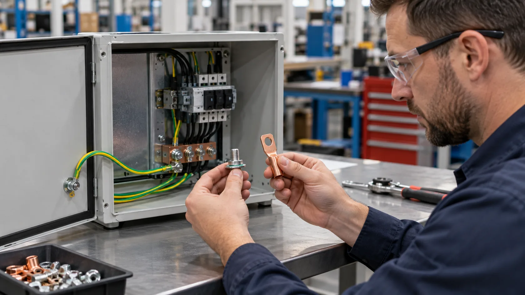
On a drawing review, the phrase “add a grounding lug” can mean two very different things. One person may mean the fixed threaded point on the enclosure. Another may mean the copper or brass fitting that holds the conductor. Both are important, but they do different jobs.
For a custom metal enclosure, a grounding stud is usually the anchored, threaded attachment point. A grounding lug is usually the conductor-termination component fitted to that point or another approved mounting surface. The complete electrical path also depends on the enclosure material, contact surface, hardware stack, assembly state, and the applicable product requirements.
This article focuses on enclosure-side design and production. The responsible electrical designer, installer, and compliance team must still define the required protective-earth, bonding, functional-ground, or EMC function and its test basis. UL’s grounding and bonding guidance is a useful reminder that metal enclosures need bonding where necessary to preserve continuity and fault-current capability.
In my factory work, the costly error is not choosing a stud or lug by its name. It is leaving the mating surfaces and hardware sequence undefined until final assembly. Start with the electrical path, then select the parts that make it repeatable.
Start With the Connection Path, Not the Part Name
Name the function and the two points being connected
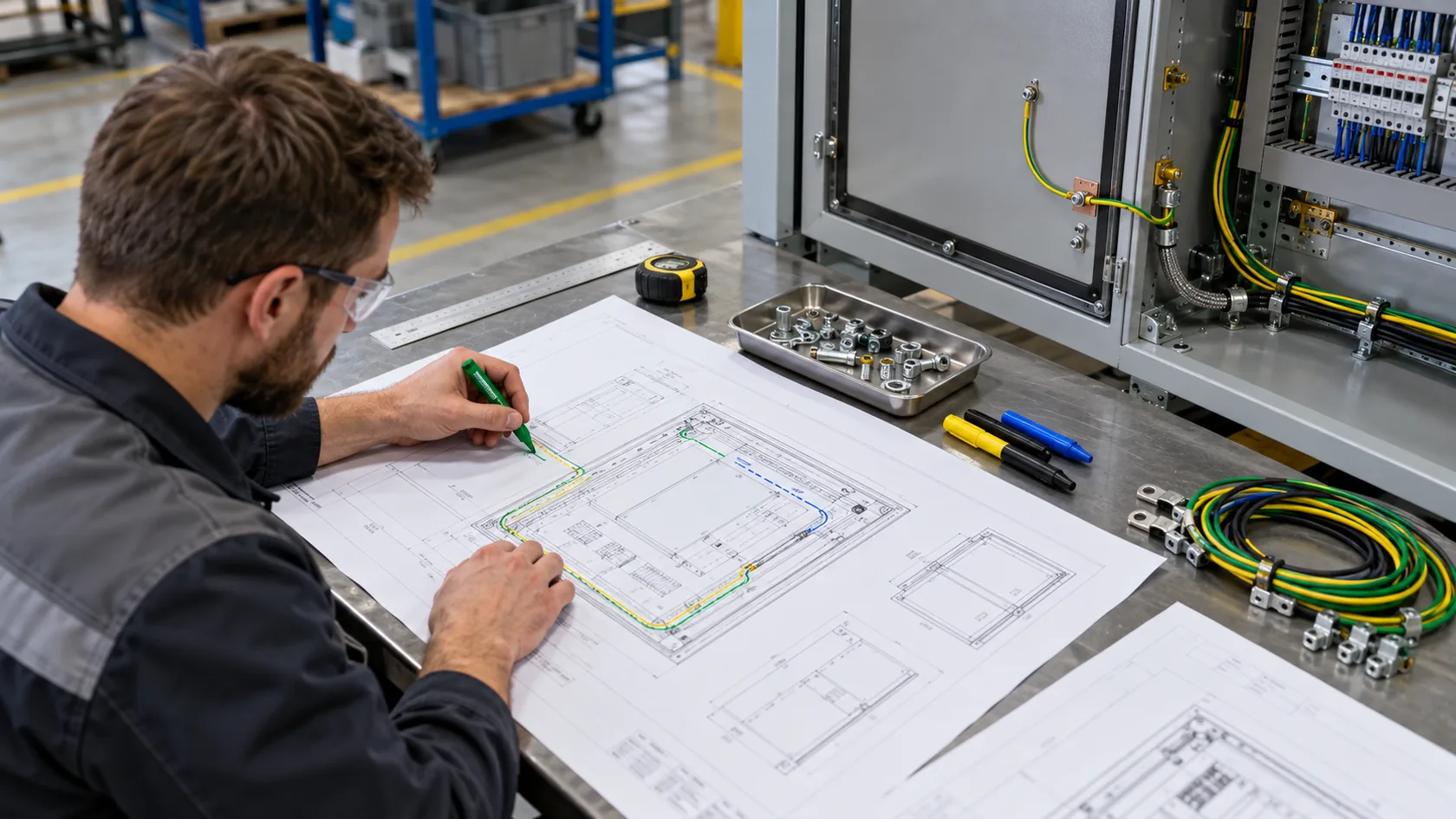
“Grounding” is often used broadly. A protective bonding path from a defined terminal to an enclosure body, a bonding jumper from a door to the chassis, a conductor to a grounding bar, and a cable-shield interface may all appear in the same product. They should not be specified as one generic ground point.
The OSHA installation rule notes that nonconductive paint or similar coating must be removed at required threads, contact points, and contact surfaces unless the fitting is designed to make that removal unnecessary. That is why the drawing needs to identify the intended surfaces instead of assuming every metal fastener makes a valid path.
| Question to answer | Why it changes the hardware choice |
|---|---|
| What is the electrical function? | Protective bonding, functional grounding, static control, and EMC can require different interfaces and evidence. |
| Which two parts must connect? | A chassis-to-conductor connection is not the same as a door-to-chassis bond. |
| What condition must be tested? | A loose panel or an open door may not represent the finished product. |
| What finish and environment apply? | Powder coating, anodizing, humidity, salt, cleaning fluids, and service access affect the contact plan. |
I ask for this small connection map before quoting hardware. It keeps a low-cost fastener from becoming an unreviewed electrical design decision.
With the endpoints clear, the distinction between a stud and a lug becomes much simpler.
What a Grounding Stud Does

A stud is the fixed attachment point
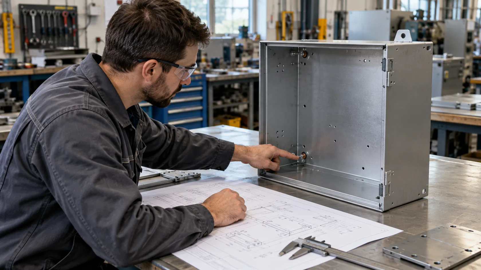
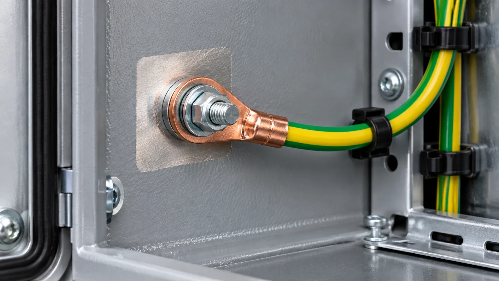
A grounding stud is typically a threaded post that is permanently attached to an enclosure, chassis, or mounting panel. Depending on the design and fabrication method, it may be welded, clinched, or otherwise fixed before finishing. Its job is to provide a durable, accessible place to assemble a terminal, ring lug, bonding strap, or other approved connection.
The stud alone is not the entire grounding solution. It needs a defined relationship to the enclosure material and a released hardware stack. A coated enclosure also needs a controlled contact land or other approved conductive interface where the design requires direct electrical contact. Parker’s industrial grounding guidance illustrates the practical assembly idea: the enclosure wall, mounting hardware, surface condition, and ground lug work together as one connection.
| Stud design question | What to define on the drawing or work instruction |
|---|---|
| Location | Accessible side of the panel, tool clearance, cable bend space, and distance from seals or cosmetic faces |
| Attachment method | The manufacturing method, panel material, and any limitations from thickness or formed geometry |
| Finish boundary | A masked land, approved treatment, or another controlled contact condition where required |
| Hardware stack | The specified nut, washer, terminal or strap, retention method, and assembly sequence |
| Service condition | Whether the point remains accessible after wiring, covers, and equipment are installed |
I prefer a dedicated stud when the design needs a repeatable attachment point and the connection will be installed or serviced more than once. A random painted screw may look convenient, but it leaves too much to chance.
The stud provides the place to connect; the lug normally provides the means to terminate the conductor.
What a Grounding Lug Does
A lug terminates or clamps the conductor
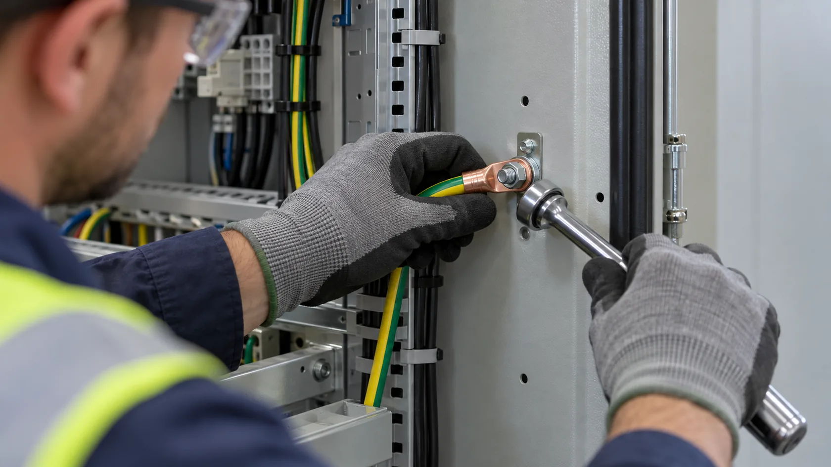
A grounding lug is a fitting designed to attach a grounding or bonding conductor to an enclosure or other conductive structure. The exact form varies. Some lugs accept a conductor in a compression or clamp section and bolt to a stud or pad. A ring terminal is another conductor-termination style often used under a nut on a stud. The component must match the conductor, the enclosure interface, and the approved electrical design.
nVent Hoffman’s grounding-accessory guide describes a grounding lug as a means of attaching a grounding conductor to an electrical enclosure. That concise definition is helpful: the lug is usually the conductor-side interface, while the stud or mounting feature is the enclosure-side attachment point.
Do not confuse a lug’s conductor capacity, plating, fastening hole, or listing with a complete enclosure qualification. The mating stud, panel, finish boundary, fasteners, mechanical protection, and installation method still matter. For assemblies subject to a defined standard or listing, select and install hardware only as the responsible design and approval requirements allow.
From a sourcing perspective, I watch for a simple mismatch: a lug may fit the wire but not the available stud, washer diameter, service clearance, or required bend radius. Solving it later can force an awkward cable route or a changed hardware stack.
Once the two roles are separated, it is easier to choose the complete interface instead of buying parts by a familiar label.
Choose the Complete Interface

Select by connection count, service access, and finished configuration
Neither a stud nor a lug is always “better.” The right choice depends on whether the design needs one conductor, several conductors, a removable component, an internal panel, or a connection that installers can reach after the enclosure is mounted.
| Interface option | Typical role | Useful when | Buyer checks |
|---|---|---|---|
| Fixed grounding stud | Anchored threaded point on enclosure | A repeatable single-point connection or strap attachment is needed | Attachment method, finish boundary, tool clearance, approved hardware stack |
| Grounding lug | Conductor termination fitting | A conductor must be attached to an approved stud, pad, or panel feature | Conductor range, mounting hole, material, listing/approval needs, torque/process requirements |
| Ring terminal on a stud | Terminated conductor or strap end | The released design calls for a bolted connection | Ring size, lug thickness, washer/nut sequence, strain relief, service access |
| Grounding bar | Multiple conductor termination points | Several internal protective conductors need an organized common point | Bar-to-enclosure bond, isolation where required, conductor capacity, labeling |
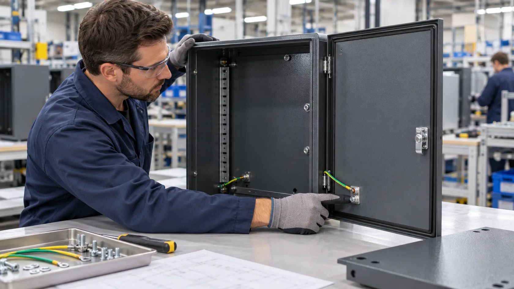
| Bonding strap | Flexible link between conductive parts | A door, cover, or moving panel needs a deliberate path | Travel, bend allowance, abrasion protection, attachment points, inspection access |
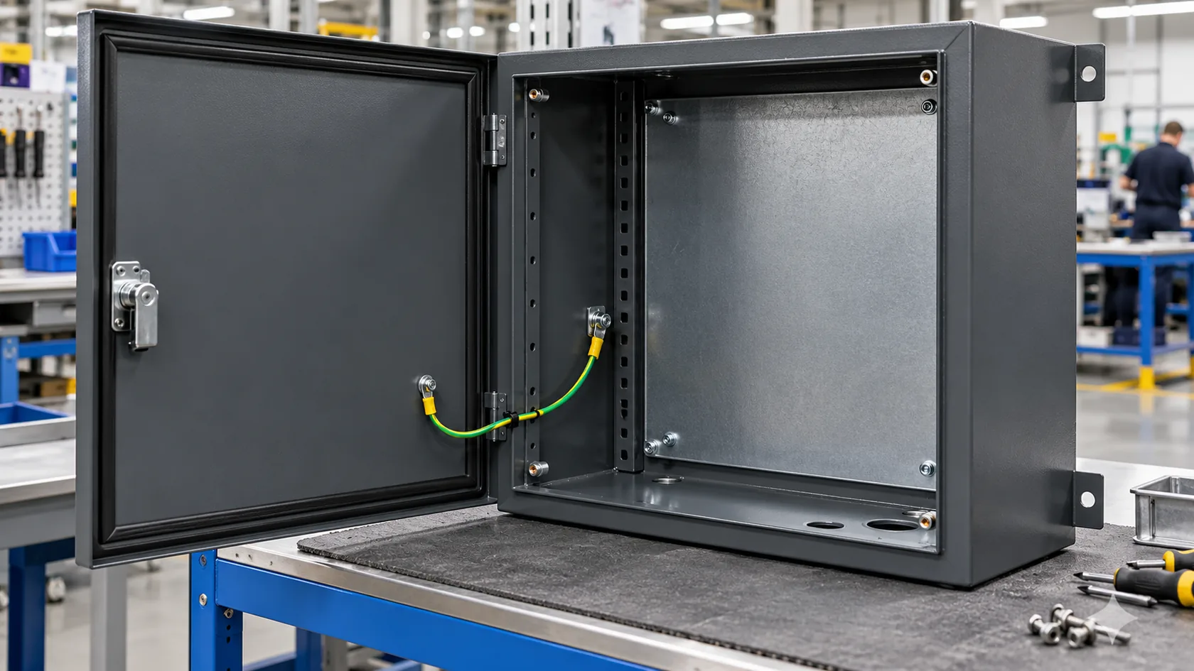
Schneider Electric documentation shows another useful real-world pattern: an enclosure can use dedicated protective-earth studs for the enclosure while a door uses its own grounding strap. This is exactly why one hardware term should not be asked to solve every connection in a cabinet.
When several functions share the same enclosure, I would rather add clear identifiers and controlled interfaces than rely on an installer to infer which stud is protective earth and which is a shield or functional-ground connection.
The selection is only reliable if the finish and assembly sequence preserve the intended interface.
Design the Stud-and-Lug Stack for a Coated Enclosure
Treat contact, corrosion, sealing, and access as one decision
Powder coating and anodizing can be valuable finishes, but they can interrupt a required conductive surface. For a ground stud or lug connection, define the surface condition at the actual mating area before coating. It may be a controlled masked land, an approved conductive treatment, or another released solution; it is not a blanket instruction to scrape paint wherever a technician sees a screw.
Keep the bare or treated area no larger than the functional interface requires, and decide how it will be protected in the real environment. Moisture, cleaning residue, dissimilar metals, vibration, repeated service, and trapped water around washers can change a once-clean contact. On a sealed enclosure, keep the grounding feature away from a gasket seating surface unless the complete interface and ingress design have been reviewed together.
For a door or removable cover, do not assume the hinge is the intended bond. If a path is required, use the released strap, contact points, routing, and service travel. A reliable electrical joint that tears when the door opens is still a failed enclosure detail.
I find that a small, clearly masked contact land with the specified hardware is easier to protect and inspect than a broad bare patch created after coating. It also gives the coater, assembler, and quality inspector the same target.
That production discipline must be confirmed on the finished, representative enclosure—not on an uncoated sample alone.
Verify the Representative Assembly
Check the released configuration and control changes
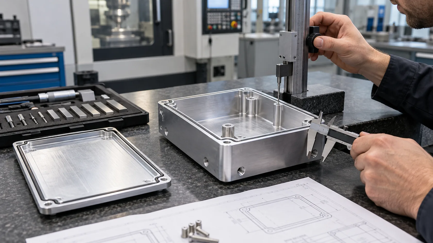
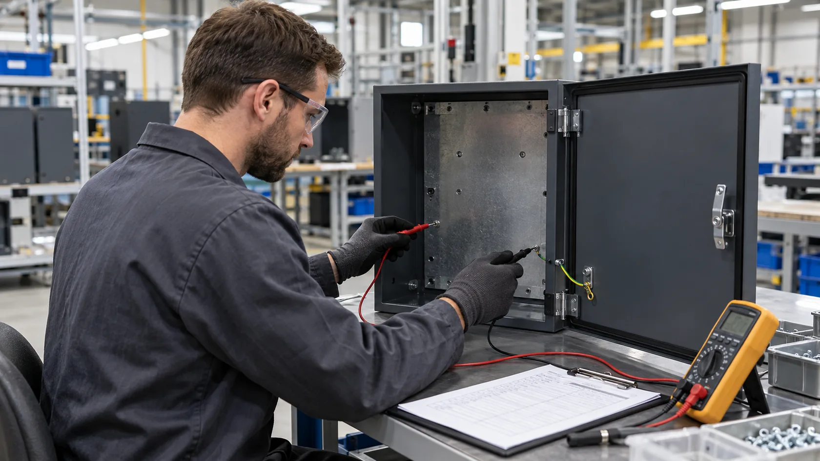
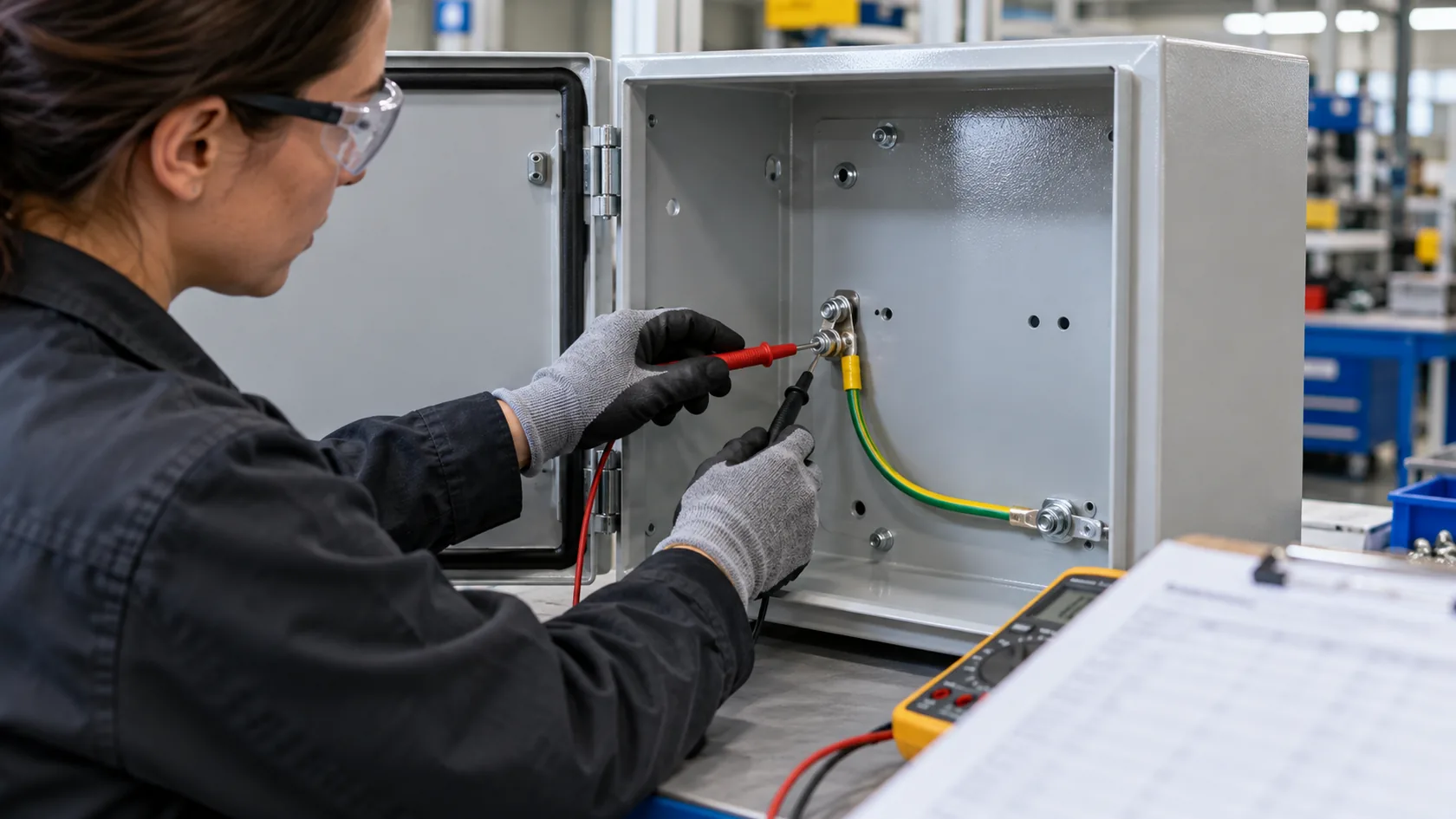
At first article, inspect the feature before and after assembly. Confirm the stud or mounting surface is in the specified place, the intended contact land is clean and accessible, the correct lug or ring terminal is installed, and the released hardware stack is present. Then use the product-defined electrical or continuity verification on the representative completed configuration.
Avoid inserting a universal resistance limit into a generic enclosure drawing. The relevant product standard, test method, probe locations, current or measurement method, assembly state, and sampling plan determine the acceptance evidence. A quick multimeter beep may confirm that a path exists at that moment, but it does not certify fault-current capability, EMC performance, or every product requirement.
Record changes that could affect the connection: a different stud supplier, panel material or thickness, coating system, masking method, lug model, washer stack, door design, or assembly instruction. These are not merely cosmetic substitutions when they alter the controlled electrical interface.
My practical release test is whether a technician can identify the correct point, fit the approved terminal without improvising, and inspect the completed stack without removing half the enclosure. If not, the drawing still needs work.
That closes the gap between a component selection and a connection the customer can actually build and maintain.
Conclusion
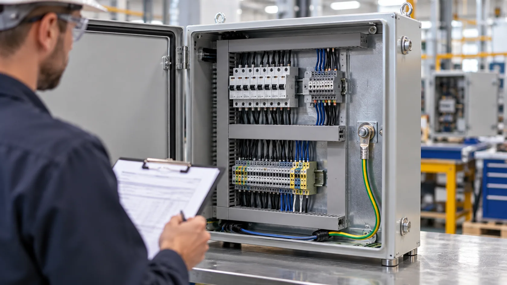
A grounding stud and a grounding lug are not competing names for the same item. The stud is usually the fixed enclosure-side attachment point; the lug is usually the conductor-termination fitting. A safe, repeatable result comes from treating them as parts of one defined path with the right contact surface, hardware stack, access, finish plan, and product-specific verification.
After years of reviewing custom enclosure drawings, I have learned that the clearest grounding detail is usually the cheapest to manufacture correctly. If you are deciding between a stud, lug, bar, or bonding strap, send the enclosure drawing, conductor information, finish specification, environment, and intended electrical function. We can review the interface before hardware and coating choices become expensive changes.